1
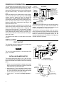
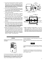
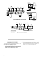
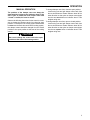
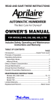
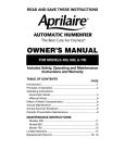
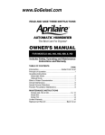
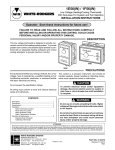
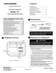
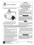
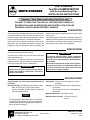
WHITE-RODGERS
2061 ZONE-AIR
Two-Wire DAMPER MOTOR
with Access-Mounting Plate
INSTALLATION INSTRUCTIONS
Operator: Save these instructions for future use!
FAILURE TO READ AND FOLLOW ALL INSTRUCTIONS CAREFULLY
BEFORE INSTALLING OR OPERATING THIS CONTROL COULD CAUSE
PERSONAL INJURY AND/OR PROPERTY DAMAGE.
DESCRIPTION
The Type 2061 Damper Motor provides a low-cost system
of zoned temperature control for warm air heating. It is of
the two-wire type, and is specially designed for use with
a two-wire thermostat with .2 Amp heat anticipator.
Each room or zone requires one damper motor and one
thermostat. The thermostat automatically controls the
passage of warm air through the duct by operating the
damper motor which is installed on the duct work to each
room or zone.
This Damper Motor-Thermostat combination may be installed on present systems for economical conversion to
zone heating. It is ideally suited for split-level and ranchtype homes having a warm air heating plant.
PRECAUTIONS
Do not exceed the specification ratings.
All wiring must conform to local and national electrical
codes and ordinances.
This control is a precision instrument, and should be
handled carefully. Rough handling or distorting components could cause the control to malfunction.
! WARNING
Do not use on circuits exceeding 30 volts. Higher
voltage will damage control and could cause
shock or fire hazard.
! CAUTION
To prevent electrical shock and/or equipment
damage, disconnect electric power to system, at
main fuse or circuit breaker box, until installation
is complete.
Do not short out terminals on gas valve or primary
control to test. Short or incorrect wiring will burn
out heat anticipator and could cause personal
injury and/or property damage.
SPECIFICATIONS
All guarantees are void if these specifications are
exceeded.
Thermostat: Use two-wire thermostat with .2 Amp
anticipator.
Electrical Ratings: The Damper Motor draws .2 Amp
Max. at 25 VAC when in the open position.
Auxiliary Contacts: Do not exceed 2.0 Amp at 25
VAC (terminals 2 and 3).
Timings: From full close to full open - Approximately
45 seconds
From full open to full close - Approximately
60 seconds.
Maximum Duct Size: 300 square inches
NOTE
The Damper Motor draws more than .2 Amp while it
is opening. For this reason, do not use more than the
recommended number of damper motors per transformer as shown on page 4.
WHITE-RODGERS DIVISION
EMERSON ELECTRIC CO.
9797 REAVIS ROAD
ST. LOUIS, MISSOURI 63123-5398
Maximum Duct Capacity: 1200 cubic feet per
minute.
Printed in U.S.A.
PART NO. 37-1499B
Replaces 37-1499
9516
PRINCIPLE OF OPERATION
This schematic shows the damper motor in the closed
position. As the thermostat calls for heat, the damper
motor is energized as a circuit is made through side “A” of
motor switch. (At the same, time a circuit is made through
the warp switch heater.) The damper motor begins to
open.
Before the damper motor reaches the full open position,
side “B” of motor switch closes (providing a low voltage
auxiliary circuit for starting oil burner or opening gas
valve), side “A” of motor switch makes with contact “C”,
and the warp switch heater opens the warp switch contacts. The warp switch heater remains energized and
keeps the warp switch contacts open as long as the
thermostat calls for heat.
When the thermostat is satisfied, the circuit through the
warp switch is broken. After this heater cools for a short
time, the warp switch contacts close, energizing the
damper motor through side “A” of motor switch. Just after
the damper motor begins closing, side “B” of motor switch
opens (breaking the auxiliary circuit), while side “A” of
motor switch makes with contact 4 just before the damper
motor fully closes.
The damper motor draws no current while in the closed
position.
Warp Switch
Contacts
(Normally Closed)
2061 Two-Wire
Damper Motor
2
110-280 or
120-280
Thermostat
To auxiliary circuit
for operating oil
burner or gas valve
2
3
Contact
“C”
4
NOTE: If same
transformer powers both
the auxiliary circuit and the
damper motor, connect
the auxiliary circuit to
terminals 1 and 3 instead
of 2 and 3.
Side “A” of
Motor Switch
Line
1
Side “B” of
Motor Switch
Transformer
Warp Switch
Heater
INTERNAL WIRING
EXTERNAL WIRING
Motor
The system is so wired so that if any one zone still calls for
heat, the burner stays on. When all thermostats are
satisfied, all dampers will have closed, and the circuit
broken to the gas valve or oil burner control.
The blower in the furnace operates as in any conventional, unzoned hot air system. When the air in the plenum
is warmed to a set temperature, the fan control turns the
blower on. When the air temperature drops, the fan
control turns the blower off. The addition of zoning has not
affected normal fan operation.
INSTALLATION
DUCT LAYOUT
This illustration shows a typical layout for a zoned warm
air system using Zone-Air Controls.
NOTE
Outlet Zone 1
BypassDamper
Bypass Duct Parts Group Supply Duct
133-0010
Outlet
Zone 2
Zone 1
DAMPER
MOTORS
The use of a bypass damper is recommended. See
page 6 for details.
Outlet
Zone 4
Zone 3
Outlet
Zone 3
INSTALLING DAMPER MOTOR
The following instructions apply for 6, 8, and 10” ducts.
(For round ducts and rectangular ducts under 6” a special
bracket is available which replaces the access-mounting
plate.)
1. Select a convenient position for damper motor installation on duct work to each zone. Carefully locate and
mark center line on each side of duct.
2. Mark location for 1⁄2” hole. Also mark locations for holes
to attach bearing plate by measuring 15⁄16” from center
of 1⁄2” hole. Drill all three holes and attach bearing plate
with two #10 sheet metal screws provided.
3. Locate point “X” on center line exactly opposite 1⁄2”
hole.
Zone 4
Duct Layout For
4 Zone Warm Air System
Return Duct
Bearing
Plate
#10 Sheet
Metal Screws
1⁄2”
Point “X”
(locate exactly
opposite 1⁄2” hole)
15⁄16”
Dia. Hole
Centerlines
of Duct
2
Zone 2
4. Use access-mounting plate as a template. Hold plate
against duct and mark the four hole locations for
attaching plate to duct. Be sure slotted hole in center
of plate is over point “X” (Fig. 1) and that edge of
plate is parallel with edge of duct. Then drill the four
holes to take #10 sheet metal screws.
5. Cut out 4” x 8” access hole through which damper vane
is to be installed. Access hole should be centrally
located between the four mounting holes.
6. Attach indicator wheel to damper shaft with two 5-40
screws with lockwashers.
7. Cut damper vane to duct size, allowing 1⁄8” minimum
clearance between duct and vane at all points. (If
required, snip notches in vane to clear protruding
sheet metal screws used to mount bearing plate.)
8. Attach vane brackets to locate damper shaft on exact
center line of damper vane. (Dimension from center
line of vane to center of holes for attaching vane
brackets is 17⁄32”.) Then start 8-32 set screws into vane
brackets.
9. Insert damper shaft through access-mounting plate,
then through vane brackets. Holding indicator wheel
flush against access-mounting plate, lock damper
shaft to vane by tightening set screws, being sure to
leave 1⁄8” minimum clearance between edge of
vane and access-mounting plate as shown.
10.Install vane through hole in duct by turning vane
sideways and slipping damper shaft into slot in bearing
plate on opposite side of duct. Push indicator wheel
flush against access-mounting plate and spin indicator wheel to assure free turning of vane. Then attach
access-mounting plate to duct and cut off damper
shaft so it extends 1” past bearing plate.
WIRING
All wiring must conform to local and national electrical codes.
AccessMounting Plate
Motor
Damper
Shaft
Damper Vane
4” x 8”
Access Hole
Indicator
Wheel
#10 Sheet
Metal Screws
Wing Nut
Access-Mounting
Plate
Damper Vane
Notches to clear
sheet metal
screws (if required)
15⁄16”
Vane
Brackets
Do not cut off
#10 Sheet
damper shaft until
vane is installed Metal Screws
8-32
Set Screws
Indicator
Wheel
5-40 Screws
With
Lockwashers
Leave 1⁄8” minimum clearance
when tightening set screw
11.Motor is shipped in closed position. Turn indicator
wheel so that yoke on bottom of motor slips into
square holes on indicator wheel when motor is placed
into position. Tighten motor firmly with wing nuts. (The
word “closed” should be visible on the indicator wheel.)
For best connections, use #18 Thermostat wire. #16 will
also work satisfactorily.
Make connections to screw terminals according to wiring
diagram.
NOTE
To check motor operation without thermostat connected,
jumper 2 to 4 to open motor. Remove jumper to close
motor.
The WR S81-0125 Transformer (40 VA) will handle up to
4 damper motors. The WR S81-0126 (20VA) will handle
up to 2 damper motors.
If the furnace manufacturer recommends a wiring diagram, follow such instructions. If none are available, the
following diagrams show suggested circuits for Type
2061 Damper motors in conjunction with two-wire thermostats (.2 Amp anticipator) and other related controls.
3
Low Voltage
Constant Ignition
Oil Burner Control
High Limit
H
Line
G
White-Rodgers Damper Motor Thermostats (Two-Wire)
2
2
2
1
1
2
2
4
3
1
2
2
4
3
2
2
4
1
3
3
1
1
2
3
Burner
Motor
x
x
4
1
T
For x
Oil x
2
2
4
T
3
For x
Gas x
3
H
LINE
G
2061 Damper Motors
Additional
Zones
G
LINE
H
H
Line
G
Transformer
S81-0126
TRANSFORMER
S81-0125
Transformer
HIGH LIMIT
LOW VOLTAGE
SILENT KNIGHT
GAS VALVE
Typical Multi-Zone Gas or Oil Fired System
2
3
1
4
PLUG-IN PILOT
White-Rodgers Damper Motor Thermostats (Two-Wire)
High Limit
H
Line
G
S81-0125
Transformer
2
2
3
1
4
3
1
3
2061 Damper Motors
26A00 Series
Low Voltage
Diaphragm Gas Valve
Typical 3-Zone Gas Fired System
CHECKING THE SYSTEM
Turn on the electricity. If gas fired, be sure pilot is lit. Then
check each zone separately as follows:
1. Turn thermostat to highest setting. Damper vane for
that zone will open and furnace burner will come on as
auxiliary circuit is made on damper motor.
4
2
2
4
1
Transformer supplies
power for low voltage
gas valve as well as
damper motors.
2
2
4
Pilot
2. Turn thermostat to lowest setting. Damper vane for
that zone will close and furnace burner will shut off as
auxiliary circuit is broken on damper motor.
OPERATION
MANUAL OPERATION
The position of the damper vane can always be
determined by looking at the indicator wheel. If the
word “open” is visible, the vane is open. If the word
“closed” is visible, the vane is closed.
Observe the following instructions in the event it is necessary to change the damper vanes from closed to open
position. For example, if the cooling system is not zoned
but does use the same duct work as the heating system,
the damper vanes should be changed from the closed
position to the open position at the start of the cooling
season.
To change damper vane from closed to open position:
Loosen wing nuts and pull damper motor back from
duct a short distance. Rotate indicator wheel 90° in
either direction so that yoke on damper motor drops
into the two round holes on indicator wheel. Then
retighten wing nuts.
To change damper vane from open to closed position:
Loosen wing nuts and pull damper motor back from
duct a short distance. Rotate indicator wheel 90° in
either direction so that yoke on damper motor drops
into the two square holes on indicator wheel. Then
retighten wing nuts.
! CAUTION
Be sure to change the vanes back to the open
position at the start of the heating season.
5
133-0010
ZONE-AIR
BYPASS DAMPER
INSTALLATION INSTRUCTIONS
DESCRIPTION
This bypass damper was designed for use with zoned
warm air heating and air conditioning systems. It is
installed in a connecting duct between the furnace plenum or the supply duct and the cold air return duct.
Its purpose is to control and compensate for excess
volume and velocity of the air due to the closing of the
dampers leading to some of the zones.
The bypass damper, operating by means of air pressure,
permits any excess volume of air to pass directly to the
cold air return, avoiding an increased air velocity through
the remaining open ducts which would result in discomfort
to the occupants of that zone.
INSTALLATION
All parts needed for the bypass damper are provided
except the damper vane. The vane should be cut from a
piece of sheet metal to the proper size to fit the duct.
If several zones are not calling for heat, the bypass
damper should be partially open; if only one zone is calling
for heat, the bypass damper should be open.
The bypass duct should be properly sized. It should be
designed to handle at least the same amount of air as the
supply duct, less that required by the smallest zone.
NOTE
The damper located in the bypass duct has a counterweighted arm. It operates through the pressure of the air
as opposed to the torque of the weighted arm. Adjust the
counterweight so that with all zones calling for heat, the
fan in operation, and all ducts open, the bypass damper
is in the closed position.
See the layout for zoned warm air system on page 2 for
additional information.
Connecting
Duct
Counterweighted Arm
Furnace
Plenum
Partially open; one
or more zones closed;
fan operating
Air pressure
bypass damper
closed; all zones
open and/or
not operating
6
Cold Air
Return
Open position;
most zones closed;
fan operating