1
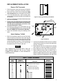
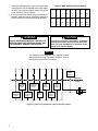
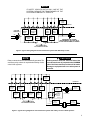
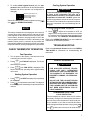
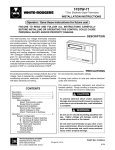
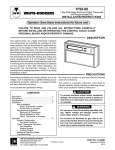
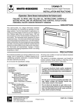
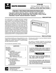
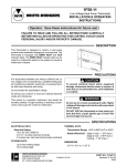
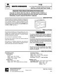
1F95-71
WHITE-RODGERS
7 Day Multi-stage Electronic Digital Thermostat
with Programmable Fan
INSTALLATION INSTRUCTIONS
Operator: Save these instructions for future use!
FAILURE TO READ AND FOLLOW ALL INSTRUCTIONS CAREFULLY
BEFORE INSTALLING OR OPERATING THIS CONTROL COULD CAUSE
PERSONAL INJURY AND/OR PROPERTY DAMAGE.
DESCRIPTION
This wall-mounted, low voltage thermostat maintains
room temperature by controlling the operation of multistage systems. Use this thermostat for applications requiring up to three stages of heat and up to two stages of
cool. Indicator lights show the system status. The user
may program up to four time and two temperature settings
per 24 hour period and may program each day independently. The thermostat will store both heating and cooling
programs simultaneously. A 9 volt Energizer® battery will
maintain the stored program for approximately one week,
if incoming power should fail. If power failure is extensive
and the program is lost, after power restoration, the
thermostat will automatically maintain a factory
preprogrammed heating temperature of 64°F or a cooling
temperature of 82°F.
PRECAUTIONS
If in doubt about whether your wiring is millivolt, line, or low
voltage, have it inspected by a qualified heating and air
conditioning contractor, electrician, or someone familiar
with basic electricity and wiring.
Do not exceed the specification ratings.
All wiring must conform to local and national electrical
codes and ordinances.
This control is a precision instrument, and should be
handled carefully. Rough handling or distorting components could cause the control to malfunction.
! CAUTION
CONTENTS
Description .......................................................... 1
Precautions ........................................................ 1
Specifications ...................................................... 2
Installation ........................................................... 2
New Installation
Select Thermostat Location
Route Wires to Location
Replacement Installation
Remove Old Thermostat
Attach Subbase to Wall
Attach Thermostat to Subbase
Operation ............................................................ 6
System Configuration
Set Option Switches
Check Thermostat Operation
Fan Operation
Heating System Operation
Cooling System Operation
Troubleshooting
R
WHITE-RODGERS DIVISION
EMERSON ELECTRIC CO.
9797 REAVIS ROAD
ST. LOUIS, MISSOURI 63123-5398
To prevent electrical shock and/or equipment
damage, disconnect electric power to system at
main fuse or circuit breaker box until installation
is complete.
! WARNING
Do not use on circuits exceeding specified voltage. Higher voltage will damage control and
could cause shock or fire hazard.
Do not short out terminals on gas valve or primary control to test. Short or incorrect wiring will
burn out heat anticipator and could cause personal injury and/or property damage.
PART NO. 37-4501D
Printed in U.S.A.
9540
SPECIFICATIONS
THIS CONTROL IS DESIGNED FOR USE WHERE BOTH SIDES OF THE TRANSFORMER ARE PRESENT TO
THE THERMOSTAT (both the hot and common sides of the 24 VAC end of the transformer.)
ELECTRICAL DATA
Electrical Rating
20 to 30 VAC 50/60 Hz.
0.01 to 1.5 Amps (Load per terminal)
2.5 Amps Maximum Total Load (All terminals combined)
Anticipation:
Heating 4 to 40
Cooling 4 to 40
} Reference Values
STAGING DATA
Up to 3 heating stages
Up to 2 cooling stages
THERMAL DATA
Setpoint Temperature Range:
40°F to 99°F (4°C to 37° C)
Operating Ambient Temperature Range:
32°F to 105°F
Operating Humidity Range:
0 to 90% RH (non-condensing)
Shipping Temperature Range:
-40°F to 150°F
ACCESSORIES
Remote Sense Kit W.R. Part No. F145-1049
Thermostat Guard W.R. Part No. F29-0198 (clear) or
F29-0238 (opaque)
INSTALLATION
NEW INSTALLATION
IT IS RECOMMENDED THAT YOU PROGRAM THE
THERMOSTAT WITH BATTERY INSTALLED BEFORE
ATTACHING ON SUBBASE. SEE OPERATION GUIDE
FOR PROGRAMMING INSTRUCTIONS.
Select Thermostat Location
Proper location insures that the thermostat will provide a
comfortable building temperature. Observe the following
general rules when selecting a location:
1. Locate thermostat about 5 ft. above the floor.
2. Install thermostat on a partitioning wall, not on an
outside wall.
3. Never expose thermostat to direct light from lamps,
sun, fireplaces or any temperature radiating equipment.
4. Avoid locations close to windows, adjoining outside
walls, or doors that lead outside.
5. Avoid locations close to air registers or in the direct
path of air from them.
6. Make sure there are no pipes or duct work in that part
of the wall chosen for the thermostat location.
7. Never locate thermostat in a room that is normally
warmer or cooler than the rest of the building.
8. Avoid locations with poor air circulation, such as
behind doors or in alcoves.
1. Probe for obstructions in partition before drilling 1⁄2”
hole in wall at selected location. Take up quarter
round and drill a small guide hole for sighting (see fig.
1). From basement, drill 3⁄4” hole in partition floor next
to guide hole. In houses without basements, drill 1⁄2”
hole through ceiling and into partition from above (see
fig. 1).
2. Through this hole drop a light chain, or 6” chain
attached to a strong cord. Snag cord in basement with
hooked wire. In houses without basements, drop cord
through hole in ceiling and down partitioning; snag
cord at the thermostat location.
3. Attach thermostat wire to cord and pull wire through
hole in wall so that 6” of wire protrudes.
1⁄2” hole for
thermostat wire
Stout cord with 6”
chain attached
Approximately
5 feet from floor
Baseboard
strip moulding
1⁄4”
guide hole
for sighting
Quarter round
removed
Route Wires To Location
NOTE
All wiring must conform with local and national electrical
codes and ordinances.
3⁄4”
hole in floor of partition
Hooked wire for snagging chain
Figure 1. Routing thermostat wires
2
REPLACEMENT INSTALLATION
Remove Old Thermostat
1. Shut off electricity at the main fuse box until installation is complete. Verify power is off with a voltmeter.
2. Remove the front cover of the old thermostat. With
wires still attached, remove wall plate from the wall.
3. If the old thermostat has a wall mounting plate,
remove the thermostat and the wall mounting plate as
an assembly.
4. Use the Cross Reference Guide to find the thermostat
type you are replacing.
5. Identify each wire attached to the old thermostat
using the labels enclosed with the new thermostat. Record the identification of the wire on the
corresponding blank in Table 1.
6. Disconnect the wires from old thermostat one at a
time. Pull at least 6 inches of wire out of the wall. DO
NOT LET WIRES FALL BACK INTO THE WALL.
7. Install new thermostat using the following procedures.
PULL STRAIGHT OUT
Figure 2. Removing thermostat from subbase
Screw
anchors
Connect wires under
terminal screws
S1 S2 S3
Mounting
hole
O
B
Y1
Y2
C
G
9-pin connector
W1
4-pin connector
R
W2
W3
Mounting
hole
Attach Subbase To Wall
1. Remove the packing material from the thermostat.
Place the fingers of one hand on the center top and
bottom portion of the thermostat. Grasp the subbase
in the other hand on the top and bottom center, and
gently pull straight out (see fig. 2). The thermostat has
pin and socket connectors. Forcing or prying on the
thermostat will cause damage to the unit.
NOTE
THIS THERMOSTAT REQUIRES BOTH THE HOT
AND COMMON SIDES OF THE 24 VAC TRANSFORMER TO BE PRESENT TO THE THERMOSTAT
FOR OPERATION.
Pull wires through
this opening
Figure 3. Subbase
2. Connect wires beneath terminal screws on subbase
using wiring schematic for your particular application
(see figs. 3 through 6).
3. Place subbase over hole in wall and mark mounting
hole locations on wall using subbase as a template.
4. Move subbase out of the way. Drill mounting holes.
5. Fasten subbase loosely to wall, as shown in fig. 3,
using two mounting screws. Place a level against
bottom of subbase, adjust until level, and then tighten
screws. (Leveling is for appearance only and will not
TABLE 1. TERMINAL REFERENCE
LABEL
NUMBER
(1)
(2)
(3)
(4)
(5)
(6)
(7)
(8)
(9)
(10)
(11)
(12)
(13)
1F95
TERMINAL
DESIGNATION
FUNCTION
G
C
Fan Output
Transformer 24 VAC Common
R
O
B
Transformer 24 VAC Hot
Changeover Output (Cooling)
Changeover Output (Heating)
Y1
Y2
W1
W2
W3
OLD THERMOSTAT
TERMINAL
DESIGNATION
Stage 1 Cool
Stage 2 Cool
Stage 1 Heat
Stage 2 Heat
Stage 3 Heat
3
affect thermostat operation.) If you are using existing
mounting holes, or if holes drilled are too large and do
not allow you to tighten subbase snugly, use plastic
screw anchors to secure subbase.
6. Push excess wire into wall and plug hole with a fireresistant material (such as fiberglass insulation) to
prevent drafts from affecting thermostat operation.
TABLE 2. WIRE IDENTIFICATION LABELS
1
G
2
C
3
L
4
R
5
O
6
B
7
E1
8
E2
G
1
C
2
L
3
R
4
O
5
B
6
E1
7
E2
8
9
Y1
10
Y2
11
W1
12
W2
13
W3
14
S1
15
S2
16
S3
Y1
9
Y2
10
W1
11
W2
12
W3
13
S1
14
S2
15
S3
16
! WARNING
! CAUTION
DO NOT EXCEED MAXIMUM VOLTAGE OR CURRENT RATINGS. FIRE, PERSONAL INJURY, AND/
OR EQUIPMENT DAMAGE COULD RESULT.
To prevent electrical shock and/or equipment
damage, disconnect electrical power at the main
fuse box until installation is complete. Verify
power is off with a voltmeter.
NOTE
The following wiring diagrams show typical terminal
identification and wiring. For proper installation, refer to
the original manufacturers’ instructions.
THERMOSTAT
CONTROL
CIRCUIT
THERMOSTAT
O
B
Y1
Y2
G
W1
W2
W3
R
C
SYSTEM
CHANGEOVER
ENERGIZED
IN HEAT
COMPRESSOR
HEAT
CONTACTOR
STAGE 2
RELAY
STAGE 1
HEAT
RELAY
STAGE 3
HOT
24 VAC
CHANGEOVER
ENERGIZED
COMPRESSOR
CONTACTOR
IN COOL
STAGE 1
FAN
RELAY
HEAT
RELAY
STAGE 2
Figure 4. Typical wiring diagram for single transformer systems
4
120 VAC
NEUTRAL
NOTE
IF SAFETY CIRCUITS ARE IN ONLY ONE OF THE
SYSTEMS, REMOVE THE TRANSFORMER OF THE
SYSTEM WITH NO SAFETY CIRCUITS.
THERMOSTAT
CONTROL
CIRCUIT
THERMOSTAT
O
G
Y2
Y1
B
W1
W2
R
W3
C
SYSTEM
CHANGEOVER
ENERGIZED
IN COOL
CUT AND
TAPE OFF!
HEAT
RELAY
STAGE 3
HEAT
RELAY
STAGE 1
COMPRESSOR
CONTACTOR
STAGE 2
HOT
HOT
24 VAC
COMPRESSOR
CONTACTOR
STAGE 1
24 VAC
120 VAC
NEUTRAL
FAN
RELAY
HEAT
RELAY
STAGE 2
CHANGEOVER
ENERGIZED
IN HEAT
120 VAC
NEUTRAL
DEPENDING ON SYSTEM
REQUIREMENTS, REPLACE WITH
A 75VA TRANSFORMER, IF NEEDED
TWO COMMONS MUST
BE JUMPERED TOGETHER!
Figure 5. Typical wiring diagram for two-transformer systems with NO safety circuits
NOTE
! CAUTION
Relay contacts shown are thermostatically operated. The
accessory relay scheme is required when safety circuits
exist in both systems.
Polarity must be observed. If the HOT side of the
second transformer is jumpered to the COMMON
side of the first transformer a short will be made.
Damage to equipment will occur when power is
restored.
THERMOSTAT
CONTROL
CIRCUIT
THERMOSTAT
O
Y1
Y2
G
B
W1
W2
W3
C
R
SYSTEM
CHANGEOVER
ENERGIZED
IN COOL
COMPRESSOR
CONTACTOR
STAGE 2
HEAT
RELAY
STAGE 3
HEAT
RELAY
STAGE 1
LIMIT OR
SAFETY
SWITCHES
LIMIT OR
SAFETY
SWITCHES
HOT
120 VAC
24 VAC
NEUTRAL
COMPRESSOR
CONTACTOR
STAGE 1
FAN
RELAY
CHANGEOVER
ENERGIZED
IN HEAT
HEATING
TRANSFORMER
24 VAC
ACCESSORY
RELAY N.O.
CONTACT
HEAT
RELAY
STAGE 2
COMMON
LIMIT OR
SAFETY
SWITCHES
TWO COMMONS MUST
BE JUMPERED TOGETHER!
COMMON
LIMIT OR
SAFETY
SWITCHES
24 VAC
HOT
120 VAC
NEUTRAL
COOLING
TRANSFORMER
Figure 6. Typical wiring diagram for two-transformer systems with safety circuits in BOTH systems
5
Attach Thermostat To Subbase
WE RECOMMEND THAT YOU SET OPTION SWITCHES
TO DESIRED POSITION BEFORE ATTACHING ON
SUBBASE (see OPERATION). WE ALSO RECOMMEND THAT YOU PROGRAM THE THERMOSTAT
WITH BATTERY INSTALLED BEFORE ATTACHING
ON SUBBASE (see OPERATION GUIDE for programming instructions).
USE
SYSTEM
SWITCH
Gently pivot the thermostat down until the 8-pin connectors and the plastic snaps lock into place (see fig. 7). Be
gentle when attaching thermostat. If the thermostat
does not seem to be attaching to the subbase easily,
make sure that the connector pins and plastic snaps are
properly aligned, and that excess wire is pushed into the
wall. Damage to the thermostat may occur if force is
used.
TO TURN THERMOSTAT OFF BEFORE
ATTACHING THERMOSTAT TO WALL. FAILURE TO
TURN THERMOSTAT OFF MAY CAUSE EQUIPMENT
DAMAGE DUE TO RAPID COMPRESSOR CYCLING.
To attach thermostat to subbase, line up the plastic snap
guides at the top of the thermostat and the 4 connector
pins on the thermostat with the connectors near the top
right section of the subbase (when viewed from the front).
ENGAGE TWO UPPER GUIDES;
PIVOT DOWN
Figure 7. Attaching thermostat to subbase
OPERATION
SYSTEM CONFIGURATION
4-pin connector
Battery
NOTE
ANY TIME OPTION SWITCHES #1 OR #2 ARE
CHANGED, THE 9 VOLT ENERGIZER® BATTERY MUST
BE REMOVED FOR A MINIMUM OF 2 MINUTES.
Set Option Switches
1. For furnaces not requiring a G terminal to energize
fan (systems with fan/limit switch or automatic fan on/
off operation):
Option switches
9-pin connector
Figure 8. Back of thermostat
ON
1
2
3
4
Switch #1 ON
Switch #2 OFF
Switch #3 (see step 4)
Switch #4 (see step 5)
2. For systems with electric furnace, and where blower
is energized through fan relay (no sequence to energize blower):
ON
1
2
3
4
Switch #1 OFF
Switch #2 OFF
Switch #3 (see step 4)
Switch #4 (see step 5)
3. For systems with an economizer for first stage cooling:
ON
1
6
2
3
4
Switch #1 (see steps 1 & 2)
Switch #2 ON
Switch #3 (see step 4)
Switch #4 (see step 5)
NOTE
Set option switches #1 and #2, install the battery, and
program the thermostat before changing option switch #3
or #4.
4. To enable total keypad lockout (ALL buttons will be
disabled and will not operate until configuration is
changed):
ON
1
2
3
4
Switch #1 (see steps 1-2)
Switch #2 (see step 3)
Switch #3 ON
Switch #4 (see step 5)
Switch #3 in ON position disables all buttons.
5. To enable partial keypad lockout (only the temperature buttons will function; all other buttons will be
disabled and will not operate until configuration is
changed):
ON
1
2
3
4
Switch #1 (see steps 1-2)
Switch #2 (see step 3)
Switch #3 (see step 4)
Switch #4 ON
Switch #4 in ON position disables all buttons except
and
(see OPERATION GUIDE).
NOTE
Cooling System Operation
! CAUTION
To prevent compressor and/or property damage,
if power to the compressor has been off or
interrupted for more than 1 hour and the outdoor
temperature is below 50°F, DO NOT operate the
system for at least the amount of time the compressor was off! This will allow the compressor heaters to
warm the compressor oils to avoid damage due to
slugging.
1. Press
SYSTEM
SWITCH
until COOL is displayed.
The battery maintains the stored program in the event of
a power failure. When attached to the wall with 24 VAC
power applied, the thermostat will function normally without the battery. However, the program will be lost in the
event of power interruption or failure if the battery is not
installed. When power is restored, the thermostat will
automatically maintain a temperature of 64°F or a cooling
temperature of 82°F (factory preprogrammed) as needed.
2. Press
to adjust the thermostat to 40°F. All
stages of the cooling system should come on within
five minutes (if the compressor is not operating, it may
be locked out. See LOCKOUT BYPASS OPTION).
Refer to the OPERATION GUIDE if you need additional
information on thermostat operation.
CHECK THERMOSTAT OPERATION
Refer to the Question & Answer section of the OPERATION GUIDE for information on troubleshooting the
thermostat.
TROUBLESHOOTING
Fan Operation
1. Turn on power to the system. If the heat source has
a standing pilot, be sure to light it.
2. Press
FAN
SWITCH
LOCKOUT BYPASS OPTION
until FAN ON is displayed. The blower
! CAUTION
should begin to operate.
3. Press
FAN
SWITCH
until FAN AUTO is displayed. The
FOR QUALIFIED SERVICE TECHNICIANS’ USE ONLY. OPERATORS
SHOULD NOT USE THIS FEATURE DUE
TO POSSIBILITY OF EQUIPMENT OR
PROPERTY DAMAGE, OR PERSONAL
INJURY.
blower should stop operating within approximately
one minute.
Heating System Operation
1. Press
SYSTEM
SWITCH
until HEAT is displayed (it may already
DO NOT USE THE LOCKOUT BYPASS
OPTION UNLESS THE COMPRESSOR OIL
HEATERS HAVE BEEN OPERATIONAL
FOR 6 HOURS AND THE SYSTEM HAS
NOT BEEN OPERATIONAL FOR AT
LEAST 5 MINUTES.
be displayed).
2. Press
to adjust thermostat to 99°F. All stages of
the heating system should begin to operate within five
minutes.
COMPRESSOR SHORT TERM
CYCLE PROTECTION
This thermostat has a built-in short term (5-minute)
time delay. During this 5-minute period, the thermostat will lock out the compressor to allow head pressure to stabilize. If you want to override this feature
while testing thermostat operation, simply press
and
VIEW
PRGM
VIEW
TEMP
buttons at the same time at initial start-up.
7
If you need further information about this product, please write to
White-Rodgers Division, Emerson Electric Co.
9797 Reavis Road
St. Louis, MO 63123-5398
Attention: Technical Service Department