1
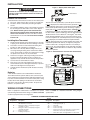
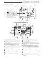
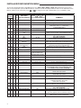
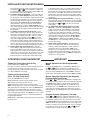
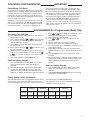
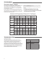
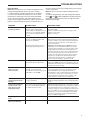
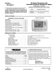
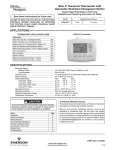
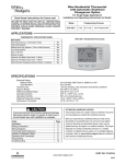
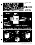
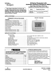
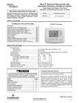
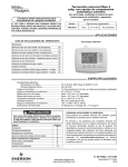
Blue Universal Thermostat with Automatic Heat/Cool Changeover Option Single Stage, Multi-Stage or Heat Pump Installation and Operating Instructions for Models: Save these instructions for future use! Model FAILURE TO READ AND FOLLOW ALL INSTRUCTIONS CAREFULLY BEFORE INSTALLING OR OPERATING THIS CONTROL COULD CAUSE PERSONAL INJURY AND/OR PROPERTY DAMAGE. 1F85-0422 1F83-0422 Programming Choices 5+1+1 Day 5+2 Day Non-Programmable Non-Programmable APPLICATIONS THERMOSTAT APPLICATION GUIDE Description Heat Pump (No Aux. or Emergency Heat) Heat Pump (with Aux. or Emergency Heat) Systems with up to 2 Stages Heat, 2 Stages Cool Heat Only Systems (with optional fan switch) Millivolt Heat Only Systems – Floor or Wall Furnaces Cool Only Systems Gas or Oil Heat 1F83-0422 Thermostat Electric Furnace Yes Yes Yes Yes Yes Yes Yes Yes Hydronic (Hot Water) Zone Heat – 2 Wires Hydronic (Hot Water) Zone Heat – 3 Wires Yes Yes SPECIFICATIONS Electrical Rating: Battery Power..................................................... mV to 30 VAC, NEC Class II, 50/60 Hz or DC Input-Hardwire.................................................... 20 to 30 VAC Terminal Load............................................................ 1.5 A per terminal, 2.5A maximum all terminals combined Setpoint Range.......................................................... 45° to 90°F (7° to 32°C) Rated Differentials: Fast Med. Slow Heat (SS1, MS2)................................................ 0.4 °F 0.6 °F 1.7 °F Cool (SS1, MS2)................................................. 0.9 °F 1.2 °F 1.7 °F Heat Pump (HP1, HP2)...................................... 0.9 °F 1.2 °F 1.7 °F Emer (HP1, HP2)................................................ 0.6 °F – 1.7 °F Operating Ambient..................................................... 32° to +105°F (0° to +41°C) Operating Humidity.................................................... 90% non-condensing max. Shipping Temperature Range.................................... -40° to +150°F (-40° to +65°C) Dimensions Thermostat............................................. 3-7/8”H x 5-1/8”W x 1-1/4”D ! CAUTION To prevent electrical shock and/or equipment damage, disconnect electric power to system at main fuse or circuit breaker box until installation is complete. Index Installation Wiring Connections Thermostat Quick Reference Installer Configuration Menu Operating Your Thermostat Programming Troubleshooting Page 2 2 3 4 6 7 8 ATTENTION: MERCURY NOTICE This product does not contain mercury. However, this product may replace a product that contains mercury. Mercury and products containing mercury must not be discarded in household trash. Do not touch any spilled mercury. Wearing non-absorbent gloves, clean up any spilled mercury and place in a sealed container. For proper disposal of a product containing mercury or a sealed container of spilled mercury, place it in a suitable shipping container. Refer to www.thermostat-recycle.org for location to send product containing mercury. PART NO. 37-7240B www.white-rodgers.com www.emersonclimate.com Replaces 37-7240A 1 1316 INSTALLATION ! Figure 1 – Battery door shown open WARNING Thermostat installation and all components of the control system shall conform to Class II circuits per the NEC code. “AA” Alkaline Batteries Remove Old Thermostat A standard heat/cool thermostat consists of three basic parts: 1) The cover, which may be either a snap-on or hinge type. 2) The base, which is removed by loosening all captive screws. 3) The switching subbase, which is removed by unscrewing the mounting screws that hold it on the wall or adapter plate. Before removing wires from old thermostat, label each wire with the terminal designation from which it was attached. Disconnect the wires from the old thermostat one at a time. Do not let wires fall back into the wall. Thermostat can be powered by system AC power or Battery. If is displayed, the thermostat is battery powered. If is not displayed, thermostat is system powered with optional battery back-up. When battery power remaining is approximately half, the will be displayed. When “Change ” is displayed, install fresh “AA” alkaline batteries immediately. For best results, replace all batteries with new premium brand alkaline batteries such as Duracell® or Energizer®. We recommend replacing batteries every 2 years. If the home is going to be unoccupied for an extended period (over 3 months) and is displayed, the batteries should be replaced before leaving. When less than two months of battery life remain, the setpoint temperature will offset by 10 degrees (10 degrees cooler in Heat mode / 10 degrees warmer in Cool mode). If offset occurs, the normal setpoint can be manually reset with or . Another offset will occur within two days if batteries are not replaced. Installing New Thermostat 1) 2) 3) 4) 5) 6) 7) Pull the thermostat body off the thermostat base. Forcing or prying on the thermostat will cause damage to the unit. Place base over hole in wall and mark mounting hole locations on wall using base as a template. Move base out of the way. Drill mounting holes. If you are using existing mounting holes and the holes drilled are too large and do not allow you to tighten base snugly, use plastic screw anchors to secure the base. Fasten base snugly to wall using mounting holes shown in Figure 2 and two mounting screws. Leveling is for appearance only and will not affect thermostat operation. Connect wires to terminal block on base. Push excess wire into wall and plug hole with a fire resistant material (such as fiberglass insulation) to prevent drafts from affecting thermostat operation. Carefully line the thermostat up with the base and snap into place. Figure 2 – Thermostat base and rear view of thermostat Mounting Hole Place Level across Mounting Tabs (for appearance only) Mounting Hole Place Level across Mounting Tabs (for appearance only) Batteries 2 “AA” alkaline batteries are included with the thermostat. To install the batteries, pull the battery door as shown by the arrow and lift open. Using the polarity indicated inside the battery door, insert the batteries. To close the battery door, swing the door down while pulling in the direction of arrow. Once fully down, snap the door back into position. To replace the batteries, set system to OFF. WIRING CONNECTIONS Refer to 37-6895 for 1F83-0422/1F85-0422 wiring diagram specifications. Refer to equipment manufacturers’ instructions for specific system wiring information. After wiring, see CONFIGURATION section for proper thermostat configuration. TERMINAL DESIGNATION DESCRIPTIONS 2 Terminal Designation Description L...............Heat pump malfunction indicator for systems with malfunction connection O...............Changeover valve for heat pump energized constantly in cooling B...............Changeover valve for heat pump energized constantly in heating Y...............Compressor Relay Y2..............2nd Stage Compressor W/E.............Heat Relay/Emergency Heat Relay (Stage 1) W2..............2nd Stage Heat (HP 1) G...............Fan Relay RH..............Power for Heating RC..............Power for Cooling C...............Common wire from secondary side of cooling system transformer or heat only system transformer 6...............3 Wire Zone Valve – Energized when no call for Heat Terminal Designation Description THERMOSTAT QUICK REFERENCE Home Screen Description Figure 3 – Home Screen Display Displays the power level of the 2 “AA” batteries: indicates good power level indicates batteries at about half power. “Change ” indicates batteries are low and should be replaced with 2 new premium brand “AA” Alkaline batteries. (See page 2 for more details) Setting Temperature Room Temperature Time of day (1F85 only) P Mo Set FAN Auto SYSTEM Heat System Indicator Menu Fan Indicator Figure 4 – Programming & Configuration Items 13 12 3 1 9 2 4 Mo Tu We Th Fr Sa Su P Date Set Temp Hold Save Month Call For Service Year Change Hold Filter System On 2 Auto Sched Cool Savings Heat Pump SYSTEM Heat Emer Auto Cool Off Time FAN On Auto Run Sched 5 6 Programming and Configuration Items 1 “System On” indicates when heating or cooling stage is energized, “+2” flashing indicates when a second stage is energized. 2 The word HOLD is displayed when the thermostat is in the HOLD mode. Temp HOLD is displayed when the thermostat is in a Temporary HOLD mode. Displays Change Filter when the system has run for 3 the programmed filter time period as a reminder to change or clean your filter. 4 Displays “Set” for setpoint when in Run Program mode. 5 Displays System Mode (Heat, Emer, Auto, Cool, Off) or Time in menu mode. 6 Displays Fan Mode (On, Auto) or “Run Sched” in Menu mode. 7 Displays “Run Schedule”, “Schedule”, or “Menu”. 14 8 10 11 Run Schedule Menu 7 8 Displays “Save” when Cool SavingsTM is working. 9 Displays “Heat Pump” when system is configured as Heat Pump thermostat. Displays “Hold” in programmable mode when not in 10 “Hold” mode. Displays Light Bulb in non-programmable mode. 11 Initially displays “Auto Sched”. If Auto Schedule had been used or disabled, then it displays “Cool Savings” when in the Cool Mode if Cool Savings has been enabled in the menu. 12 “Call For Service” indicates a fault in the heating/ cooling system, it does not indicate a fault in the thermostat. 13 Alternates Time of Day and “LOC” when keypad lockout is enabled. 14 In Configuration Menu, shows screen number. If blank, thermostat is earlier model and requires instruction sheet 37-7136A. 3 INSTALLER/CONFIGURATION MENU To enter the Configuration Menu, SYSTEM must be set to HEAT, COOL, EMER or AUTO. With thermostat in Heat, Cool or Auto, in normal operation, press the Menu button for at least 5 seconds. The display will show item #1 in the table below. Press Menu to advance to the next menu, Press or to change an item option. Shaded items are not available to 1F83. INSTALLER/CONFIGURATION MENU MENU SCREEN # MS/ DISPLAYED or to Press SS (FACTORY DEFAULT) select from listed options 1F85 1F83 HP 01 01 4 02 03 02 03 04 04 05 05 06 — 07 06 08 07 09 08 10 09 11 12 10 11 13 14 12 13 15 14 16 17 18 15 16 — 19 — 20 — 21 (OFF) Lk L (000) Lk (MS 2) 001 to 999 HP 1, SS 1 (GAS) (ELE) (0) CS (On) E (ME) CR Heat (ME) CR Cool (ME) CR Heat Pump (FA) CR Emer (OFF) CL Heat-Auto-Cool-Off ELE GAS 1, 2, 4, 5, 6 OFF SL, FA SL, FA SL, FA SL (On) dL 0 (current temperature) °F L (90) Heat L (45) Cool P3 CL On Auto-Off, Cool-Off, Heat-Off without Fan, Heat-Off Heat-Cool-Off dL OFF 1 HI, 2 HI, 3 HI, 4 HI, 1 LO, 2 LO, 3 LO, 4 LO °C L 62 to L 89 L 46 to L 82 P0, P2 (On) AS Heat OFF (On) AS Cool OFF 17 (On) FA Heat OFF 22 18 (On) FA Cool OFF 23 19 (OFF) CA On 24 — (On) dS OFF 25 26 20 21 (OFF) Change Filter (200 h) Change Filter On 25-1975 h 27 22 (o) On Cool (b) On Heat COMMENTS Selects Keypad Lockout. (Not available on earlier models, see 37-6894D) Selects Keypad lockout combination number Selects Multi-Stage (MS 2 No Heat Pump), Heat Pump 1 (HP 1, 1 compressor), or Single Stage (SS 1) Select Gas or Electric heat Selects Cool Savings Value 1 (low) to 6 (high), Value 0 Disables Feature Selects Energy Management Recovery (EMR) On or OFF. 1F85 only Adjustable Anticipation: Selects heating cycle rate for MS or SS Adjustable Anticipation: Selects the cycle rate for cooling (only when MS2 or SS1 is selected in item 1) Adjustable Anticipation (Heat Pump) (only when heat pump is selected in #1) Selects the cycle rate for Emergency mode and Auxiliary stage if Heat Pump is selected in item 1) Compressor Lockout Time Selects System Mode Configuration Selects Display Light On or OFF Adjustable Ambient Temperature Display Selects Fahrenheit/Celsius Temperature Display Selects Limited HEAT Range Selects Limited COOL Range Defaults for 5+1+1 programming (P3) but nonprogrammable (PO) or 5+2 programming (P2) is available on most models. 1F85 only Automatic Schedule for heat mode. 1F85 only. NA to Cool only system. Automatic Schedule for cool mode. 1F85 only. NA to Heat only system. Fast Heat option may be disabled by selecting OFF. NA to SS config. NA to Cool only system. Fast Cool option may be disabled by selecting OFF. NA to SS config. NA to Heat only system. Selects active Comfort Alert On or OFF. Require CA II Module. (Not available on earlier models) Selects Automatic daylight Savings Time option On or OFF. 1F85 only Selects Filter Change-out Indicator On or OFF. Change Filter time in 25 hour increments. This menu only appears if On is selected in above. Selects operation of the reversing valve terminal (O/B) output as an O or B terminal. INSTALLER/CONFIGURATION MENU 1 & 2)Keypad Lockout – This menu selection will display “Lk” and “OFF” (default, keypad not locked out). The and are used to toggle the selection between OFF and “L” (keypad locked out). When the keypad lockout selection is enabled “L”, and the MENU button is pressed again, the display will indicate the number “0” (default, still disabled) in the time digits. The are used to set the combination number from 0 and to 999. If a combination of 0 is selected and the MENU button is pressed, the menu will be exited and keypad will not be locked. If 1 to 999 is selected and the MENU button is pressed, the combination is stored into memory and the menu is exited. The “LOC” will display designating keypad locked with a valid combination. The SYSTEM button will operate for 10 seconds after the menu mode is exited to allow the user to change the mode from “OFF” to the desired SYSTEM mode. While the keypad is locked out, a press of MENU will enter the configuration menu. The first menu item displayed or keys are is the combination code “0”. The used to set the combination unlock number from 0 to 999. If the unlock number matches exactly with the combination lock number stored in memory when the MENU button is pressed, the keypad is unlocked and the “LOC” is removed. If the unlock number does not match when the MENU button is pressed, the combination returns to “0” for another attempt to set the unlock code. To exit the menu without unlocking the keypad, press RUN SCHED. To reset the combination code and unlock the keypad if the code is forgotten, see troubleshooting section. 3) This control can be configured for: MS 2 – Multi-Stage System (no heat pump) HP 1 – Heat Pump with one stage of compressor SS 1 – Single Stage System 4) GAS or Electric (ELE) fan operation. If the heating system requires the thermostat to energize the fan, select ELE. Select GAS if the heating system energizes the fan on a call for heat. 5) Select Cool Savings™ value – Selects the amount of adjustment for the Cool Savings™ feature in Cool mode with 1 (1°) being the least amount of adjustment and 6 (6°) being the most amount of adjustment. Default value is 0 which disables this feature. Cool Savings is an optional energy saving feature that can reduce your cooling costs. It is based on the principal that lower indoor humidity makes a slightly higher temperature feel more comfortable. Cool Savings operates during periods of high demand which normally occur on the hottest summer days when a cooling system may run for hours to reach the thermostat setting. Long cooling run times also lower the indoor humidity. Cool Savings, very slowly, adjusts the setpoint temperature to make the setpoint closer to the displayed room temperature, to a maximum of the number of degrees you select. Adjusting the setpoint temperature over a long cooling run time allows the system to reach your set temperature and turn off. The room temperature will actually be higher than the thermostat displays but the reduction in humidity will allow comfort at the slightly higher temperature. To turn this feature on in the Cool mode press Cool Savings. The display will show “Save” next to the setpoint temperature. When Cool Savings is making adjustments to the room temperature display “Save” will be flashing and the displayed room temperature may vary within the adjustment range you selected. If “Save” is not displayed and this feature is OFF, no change will occur when the cooling system is continuously running during periods of high demand. 6) Energy Management Recovery: (this step is skipped if configured to be non-programmable). Energy Manage- ment Recovery (E) On enables the thermostat to start heating or cooling early to make the building temperature reach the program setpoint at the time you specify. Heating will start 5 minutes early for every 1° of temperature required to reach setpoint. Example: E On is selected and your heating is pro- grammed to 65° at night and 70° at 7 AM. If the building temperature is 65°, the difference between 65° and 70° is 5°. Allowing 5 minutes per degree, the thermostat setpoint will change to 70° at 6:35 AM. Cooling allows more time per degree, because it takes longer to reach set temperature. 7, 8, 9 & 10) Cycle Rate Selection – The factory default setting for Heat and Cool modes, SS1 and MS2 is medium cycle (ME). For Heat Pump and HP1, the default setting is medium (ME). For Emer (Aux) the default setting is fast or cycle (FA). To change cycle rate, press the key. Cycle rate differentials for different settings are: Fast Medium Slow MODE FA ME SL Heat (SS1, MS2) 0.4°F 0.6°F 1.7°F Cool (SS1, MS2) 0.9°F 1.2°F 1.7°F Heat Pump (HP1) 0.9°F 1.2°F 1.7°F Emer (HP1) 0.6°F - 1.7°F 11) Select Compressor Lockout CL OFF or ON – Selecting CL ON will cause the thermostat to wait 5 minutes between cooling cycles. This is intended to help protect the compressor from short cycling. Some newer compressors already have a time delay built in and do not require this feature. Your compressor manufacturer can tell you if the lockout feature is already present in their system. When the thermostat compressor time delay occurs, it will flash the setpoint for up to five minutes. 12) System Mode Configuration – This thermostat is configured for Heat and Cool with Auto Changeover (SYSTEM switch with Heat, Auto, Cool, Off). It can also be configured for Heat and Cool (Heat, Cool, Off), Heat only with Fan (Heat, Off, FAN Switch) Heat only without Fan (Heat, Off) Auto only (Auto, Off) and Cool only (Cool, Off). 13) Select Backlight Display – The display backlight improves display contrast in low lighting conditions. When the “C” terminal is powered, selecting backlight CdL ON will keep the light on continuously. Select backlight OFF will turn the light on momentarily after any key is pressed. When the “C” terminal is not powered, the light will be on momentarily after any key is pressed no matter whether the backlight is selected ON or OFF. 14) Select Temperature Display Adjustment 4 LO to 4 HI – Allows you to adjust the room temperature display up to 4° higher or lower. Your thermostat was accurately calibrated at the factory, but you have the option to change the display temperature to match your previous thermostat. The current or adjusted room temperature will be displayed. 15) Select F° or C° Readout – Changes the display readout to Celsius or Fahrenheit as required. 16) Limited Heat Range – This feature provides a maximum setpoint temperature for heat. The default setting is 90°F. It can be changed between 62°F and 89°F by pressing or key. the 17) Limited Cool Range – This feature provide a minimum setpoint temperature for cool. The default setting is 45°F. It can be changed between 46°F and 82°F by pressing or key. the 18) Program Options: 1F85 only, configured for 5+1+1 day or 5+2 day programming or non-programming mode. The default setting is P3, indicating 5+1+1 day programming. 5 INSTALLER/CONFIGURATION MENU The programs per week can be changed to P2 or P0 by or keys. A selection of 0 Days for pressing the non-programmable will eliminate the need for EMR, and that step in the menu will be skipped. 19 & 20)Select Automatic Schedule – 1F85 only, with just one touch of the Auto Schedule key this feature allows you to program a desired comfort temperature into all the program periods along with a 6° set back for night periods of both Heat and Cool programs. Factory default is “On” for both. When Heat AS On and Cool AS On are activated while in Heat or Cool mode, select desired setpoint temperature and press Auto Schedule. This value will be copied into all the morning, day and evening program periods. The night program periods will have a 6°F set back. 21 & 22)Select Fast Second Stage ON or OFF – Heat pump or Multi-stage only, in the run mode, with the fast Heat feature enabled (FA Heat On), if the Heat setpoint temperature is manually raised by 3°F (2°C) or more the second above the actual temperature using stage will energize immediately. With FA OFF, second stage will not energize until the setpoint temperature is 1°F or more above actual temperature for more than ten minutes. The Fast Cool feature (FA Cool) provides the same controls when the setpoint temperature is lowered. 23) Comfort Alert with Active Protection – Turn this feature ON to enable active protection. This allows the thermostat to identify fault codes sent by the Comfort Alert module when compressor damage is possible and react to those codes by turning the compressor off. Fault codes from the Comfort Alert module will flash on the thermostat. (Refer to Comfort Alert Yellow Alert Codes OPERATING YOUR THERMOSTAT Choose the Fan Setting (Auto or On) Set the FAN Switch to Auto or On. Fan Auto is the most commonly selected setting and runs the fan only when the heating or cooling system is on. Fan On runs the fan continuously for increased air circulation or to allow additional air cleaning. Choose the System Setting (Heat, Off, Cool, Auto, Emer) Press the SYSTEM button to select: Heat: Thermostat controls only the heating system. Off: Heating and Cooling systems are off. Cool: Thermostat controls only the cooling system. Auto: Auto Changeover is used in areas where both heating and cooling may be required on the same day. AUTO allows the thermostat to automatically select heating or cooling depending on the indoor temperature and the selected heat and cool temperatures. When using AUTO, be sure to set the Cooling temperatures more than 1° Fahrenheit higher than the heating temperature. Emer: (Heat Pump models) Thermostat controls only backup heating system. 6 in Troubleshooting section.) If a Comfort Alert module is not connected, or to disable active protection, turn this feature OFF. If a Comfort Alert module is connected and this feature is turned OFF, the thermostat will still receive and flash the fault codes from the Comfort Alert module, but the active protection will not be enabled to protect the compressor. 24) Select Daylight Saving Time Calculation – 1F85 only, this feature will allow the thermostat to calculate the DST automatically and apply it to the Real Time Clock display. or touch keys to select the Default On. Use feature OFF. 25 & 26)Select Filter Replacement Reminder and Set Run Time – Select the “Change Filter” reminder On or OFF. If selected On, press MENU to select the time period from 25 to 1975 hours in 25 hours increments. In a typical system, 200 hours (default) of run time is approximately 30 days. After the selected time of blower operation, the thermostat will display “Change Filter” as a reminder to change or clean your air filter. When “Change Filter” is displayed, press MENU or RUN SCHED button to clear the display and restart the time to the next filter change. 27) Select Reversing Valve Output – The O/B option is factory set at “O” position. This will accommodate the majority of heat pump applications, which require the changeover relay to be energized in COOL. If the thermostat you are replacing or the heat pump being installed with this thermostat requires a “B” terminal, to energize the changeover relay in HEAT, the O/B option should be set at “B” position. IMPORTANT! Manual Operation for Non-Programmable Mode Press the SYSTEM button to select Heat or Cool and use the or buttons to adjust the temperature to your desired setting. After selecting your desired settings you can also press the SYSTEM button to select AUTO to allow the thermostat to automatically change between Heat and Cool. Manual Operation (Bypassing the Program) Programmable Thermostats Press or and then the HOLD button and adjust the temperature wherever you like. This will override the program. The HOLD feature bypasses the program and allows you to adjust the temperature manually, as needed. Whatever temperature you set in HOLD will be maintained 24 hours a day, until you manually change the temperature or press RUN SCHED to cancel HOLD and resume the programmed schedule. Program Override (Temporary Override) Press or buttons to adjust the temperature. This will override the temperature setting for four hours. To cancel the temporary setting at any time and return to the program, press Run Sched. If the SYSTEM button is pressed to select AUTO the thermostat will change to Heat or Cool, whichever ran last. If it switches to heat but you want cool, or it changes to cool but you want heat, press both and buttons simultaneously to change to the other mode. OPERATING YOUR THERMOSTAT Second Stage Time Delay Your thermostat is designed to determine the optimum time to activate the second stage. Simply raising the temperature in heating or lowering it in cooling will not always force the thermostat to bring the second stage on quickly. There is a time delay from 0-30 minutes depending on the performance of the first stage of the system. EXAMPLE: For the last 2 hours the thermostat is set on 70° and the room temperature is 70° with the equipment using only the first stage of heat. Since the equipment is keeping the temperature within 1° of setpoint, the thermostat will IMPORTANT! delay second stage for a longer time if you manually raise the temperature or if the room temperature quickly changes. Once the second stage comes on, it will come on sooner the next time there is a difference between the setpoint and the room temperature. The net effect of the staging program is that when the first stage is capable of making temperature the second stage will delay longer. When the thermostat calculates that first stage cannot make temperature in a reasonable time, the second stage will come on sooner. This built in function automatically optimizes the use of additional stages of heat or cool. PROGRAMMING (For Programmable Model Only) Set Current Time and Date 1) Press MENU and then TIME button once. The display will show the hour only. 2) Press and hold either the or key until you reach the correct hour and AM/PM designation (AM begins at midnight, PM begins at noon). 3) Press TIME once again. The display window will show the minutes only. 4) Press and hold either the or key until you reach the correct minutes. 5) Additional presses of TIME will advance the display to show the year, month and date of month. Press the or key to change the display to the correct setting for each. 6) Press RUN SCHED to exit the TIME mode. Enter the Heating Program 1) Press SYSTEM button to select “Heat” in the system switch area indicating the active mode being programmed. 2) Press the MENU button and then press SCHEDULE. 3) The top of the display will show the day(s) being programmed. The time and temperature (flashing) are also displayed. “1” will also be displayed to indicate the period. 4)Press or key to change the temperature to your selected temperature for the 1st heating period. 5) Press TIME button, time will flash. 6)Press or key to adjust the start time for the 1st period. 7) The time will change in 15 minute increments. 8) After you have set the time and the temperature for the period to begin, press SCHEDULE to advance to the next program period. 9) Repeat steps 2 through 8 until all of the program times and temperatures are set for all program periods on that day. 10) Press SCHEDULE to the next day and repeat steps 2 through 9. 11) When programming is complete and all of the times and temperatures match your desired heating schedule, press RUN SCHEDULE. The thermostat will now run your program. Enter the Cooling Program 1) Press SYSTEM button to select “Cool” in the system switch area indicating the active mode being programmed. 2)Follow Enter Heating Program instructions for entering cooling times and temperatures. Energy Saving Factory Pre-Program The 1F85-0422 thermostats are programmed with the energy saving settings shown in the table below for all days of the week. If this program suits your needs, simply set the thermoWake Up (Period 1) stat clock and press the RUN SCHED button. The table below shows the factory set heating and cooling schedule for all days of the week. Leave For Work (Period 2) Return Home (Period 3) Go To Bed (Period 4) Heating Program 6:00 AM 70°F 8:00 AM 62°F 5:00 PM 70°F 10:00 PM 62°F Cooling Program 6:00 AM 75°F 8:00 AM 83°F 5:00 PM 75°F 10:00 PM 78°F 7 PROGRAMMING Planning Your Program – Important The Heating and Cooling Program schedules below allow you to pencil in your own program times and temperatures. The 1F85-0422 comes configured for 5+1+1 day programming and can also be configured for 5+2 day programming (see configuration section). Factory settings are listed on Monday through Friday, Saturday and Sunday. If you are re-programming a 5+2 day schedule, pencil in your own times and temperatures directly below the factory times and temperatures. If you are re-programming a 5+1+1 fill in all lines with the times and temperatures you want. Keep the following guidelines in mind when planning your program. • In Heating, lower temperatures will save energy. • In Cooling, higher temperatures will save energy. • If you plan on using Auto Changeover, do not program the heating higher than the cooling. Worksheet for Re-Programming 5+2 Day and 5+1+1 Day Program Heating Program Wake Up (Period 1) Leave For Work (Period 2) Return Home (Period 3) Go To Bed (Period 4) 6:00 AM 70°F 8:00 AM 62°F 5:00 PM 70°F 10:00 PM 62°F Sat-Sun or Sat 6:00 AM 70°F 8:00 AM 62°F 5:00 PM 70°F 10:00 PM 62°F Sun 5+1+1 only 6:00 AM 70°F 8:00 AM 62°F 5:00 PM 70°F 10:00 PM 62°F Mon-Fri Cooling Program Wake Up (Period 1) Leave For Work (Period 2) Return Home (Period 3) Go To Bed (Period 4) 6:00 AM 75°F 8:00 AM 83°F 5:00 PM 75°F 10:00 PM 78°F Sat-Sun or Sat 6:00 AM 75°F 8:00 AM 83°F 5:00 PM 75°F 10:00 PM 78°F Sun 5+1+1 only 6:00 AM 75°F 8:00 AM 83°F 5:00 PM 75°F 10:00 PM 78°F Mon-Fri TROUBLESHOOTING Comfort Alert Codes The Comfort Alert diagnostics product monitors the air conditioning outdoor systems with single phase Copeland Scroll compressors. Abnormal system and electrical conditions are indicated by flashing ALERT codes on the yellow LED on the Comfort Alert module. The flash codes are transmitted to the thermostat by the Comfort Alert Thermostat interface module. The Comfort Alert compatible thermostat displays “Call For Service” that flashes at the same rate as the yellow LED on the Comfort Alert module. 8 Comfort Alert Yellow Alert Codes 1 Flash Long run time 2 Flashs System pressure trip 3 Flashs Short cycling 4 Flashs Locked rotor 5 Flashs Open circuit 6 Flashs Open start circuit 7 Flashs Open run circuit 8 Flashs Welded Contactor 9 Flashs Low voltage TROUBLESHOOTING Reset Operation Note: When thermostat is reset, installer configuration menu settings and programming will reset to factory settings. If a voltage spike or static discharge blanks out the display or causes erratic thermostat operation, you can reset the thermostat by removing the wires from terminals R and C (do not short them together) and removing batteries for 2 minutes. After resetting the thermostat, replace the wires and batteries. If the thermostat has been reset and still does not function correctly contact your heating/cooling service person or place of purchase. Note: Be sure to review the installer configuration menu settings. To reset the programming, clock and configuration settings, press and and the FAN button simultaneously. The thermostat should go blank and then all segments will be displayed momentarily. Symptom Possible Cause Correction Action No Heat/No Cool/No Fan (common problems) 1.Blown fuse or tripped circuit breaker. 2.Furnace power switch to OFF. 3.Furnace blower compartment door or panel loose or not properly installed. 4.Loose connection to thermostat or system. Replace fuse or reset breaker. Turn switch to ON. Replace door panel in proper position to engage safety interlock or door switch. Tighten connections. No Heat 1.Pilot light not lit. 2.Furnace Lock-Out Condition. Heat may also be intermittent. Re-light pilot. Many furnaces have safety devices that shut down when a lock-out condition occurs. If the heat works intermittently contact the furnace manufacturer or local HVAC service person for assistance. Diagnostic: Set SYSTEM Switch to HEAT and raise the setpoint above room temperature. Within a few seconds the thermostat should make a soft click sound. This sound usually indicates the thermostat is operating properly. If the thermostat does not click, try the reset operation listed above. If the thermostat does not click after being reset contact your heating and cooling service person or place of purchase for a replacement. If the thermostat clicks, contact the furnace manufacturer or a HVAC service person to verify the heating is operating correctly. 3.Heating system requires service or thermostat requires replacement. No Cool 1.Cooling system requires service or thermostat requires replacement. Same as diagnostic for No Heat condition except set the thermostat to COOL and lower the setpoint below the room temperature. There may be up to a five minute delay before the thermostat clicks in Cooling. 1.Possible short in wiring. 2.Possible short in thermostat. 3.Possible short in heat/cool/fan system. 4.FAN Switch set to Fan ON. Check each wire connection to verify they are not shorted or touching together. No bare wire should stick out from under terminal block. Try resetting the thermostat as described above. If the condition persists the manufacturer of your system or service person can instruct you on how to test the Heat/Cool system for correct operation. If the system operates correctly, replace the thermostat. Thermostat Setting & Thermostat Thermometer Disagree 1.Thermostat thermometer setting requires adjustment. The thermometer can be adjusted +/- 4 degrees. See Temperature Display Adjustment in the Configuration Menu section. Furnace (Air Conditioner) Cycles Too Fast or Too Slow (narrow or wide temperature swing) 1.The location of the thermostat and/or the size of the Heating System may be influencing the cycle rate. Digital thermostats provide precise control and cycle faster than older mechanical models. The system turns on and off more frequently but runs for a shorter time so there is no increase in energy use. If you would like an increased cycle time, choose SL for slow cycle in the Configuration menu, step 6 (heat), 7 (cool) or 8 (heat pump). If an acceptable cycle rate is not achieved, contact a local HVAC service person for additional suggestions. Heat, Cool or Fan Runs Constantly Forgot Keypad Lockout Code Thermostat does not have Menu Screen Numbers Hold MENU key for 20 seconds and the lockout will reset. 1.Earlier version of thermostat. Refer to Instruction Sheet 37-7136A. 9 NOTES 10 NOTES 11 Homeowner Help Line: 1-800-284-2925 White-Rodgers is a business of Emerson Electric Co. The Emerson logo is a trademark and service mark of Emerson Electric Co. www.white-rodgers.com www.emersonclimate.com