1
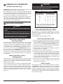
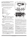
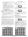
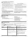
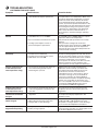
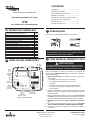
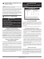
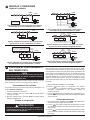
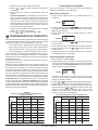
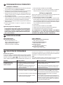
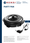
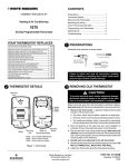
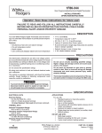
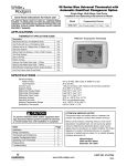
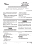
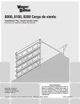
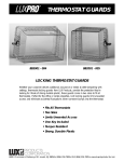
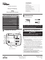
CONTENTS
Preparations................................................... 1
Thermostat Details......................................... 1
Removing Old Thermostat.............................. 1
Mounting and Wiring....................................... 2
Check Thermostat Operation.......................... 3
Programming your Thermostat....................... 4
Specifications................................................. 6
Troubleshooting.............................................. 6
Installation Instructions for
Heating & Air Conditioning
1F78
5/2 Day Programmable Thermostat
YOUR THERMOSTAT REPLACES
Typical System Compatibility Chart
Standard Heat Only Two Wire Gas or Oil Fired Systems (24 volt)
Electronic Ignition Heat Only Two Wire Systems (24 volt)
Electronic Ignition Heat Only Gas or Oil Fired Systems (24 volt)
Yes
Yes
Yes
Standard Heat/Cool Systems (24 volt)
Heat/Cool Systems Electric Heat (24 volt)
Heat Only Electric Heat Systems (24 volt)
Cool Only Systems (24 volt)
Heat Pump Systems (No Aux or Emergency Heat)
Hot Water Zone Heat Only (Two Wire) Systems
Yes
Yes
Yes
Yes
Yes
Yes
Hot Water Zone Heat Only (Three Wire) Systems
Line Voltage Heating or Baseboard 110/240 Volt Systems
Millivolt Systems Floor or Wall Furnaces
12 VDC Mobile Home Application
Multistage Systems
No
No
Yes
Yes
No
Systems Exceding 30VAC, 1.5 Amp
No
2
1
1F78
Assemble tools required below.
FLAT BLADE SCREWDRIVER
HAND OR POWER
DRILL WITH 3/16 INCH
DRILL BIT, IF NEEDED
WIRE CUTTER/STRIPPER
Failure to follow and read all instructions carefully
before installing or operating this control could cause
personal injury and/or property damage
3
THERMOSTAT DETAILS
Mounting
hole
-
+
W903
Clip to
Disable
EMR
Feature
Mounting
hole
W905
Clip for
Hydronic
System
-
+
W
RH
G
W903
W904
W9 05
ELEC GAS
W904
Clip for
Celsius Display
Electric/Gas
Switch
Figure
base
Figure1.1.Thermostat
Thermostat base
B
O
PREPARATIONS
RC
Y
REMOVING OLD THERMOSTAT
! CAUTION
To prevent electrical shock and/or equipment damage,
disconnect electrical power to the system at the main fuse
or circuit breaker until installation is complete.
Before removing wires from old thermostat’s switching subbase,
label each wire with the terminal designation it was removed
from.
1. Remove Old Thermostat: A standard heat/cool thermostat
consists of three basic parts:
a. The cover, which may be either a snap-on or hinge type.
b. The base, which is removed by loosening all captive screws.
c. The switching subbase, which is removed by unscrewing the mounting screws that hold it on the wall or adaptor plate.
2. Shut off electricity at the main fuse box until installation is
complete. Ensure that electrical power is disconnected.
3. Remove the front cover of the old thermostat. With wires still
attached, remove wall plate from the wall. If the old thermostat
has a wall mounting plate, remove the thermostat and the wall
mounting plate as an assembly.
4. Identify each wire attached to the old thermostat.
5. Disconnect the wires from the old thermostat one at a time. DO
NOT LET WIRES FALL BACK INTO THE WALL.
6. Install new thermostat using the following procedures.
White-Rodgers is a division
of Emerson Electric Co.
www.white-rodgers.com
PART NO. 37-6614B
Replaces 37-6614A
0731
3
REMOVING OLD THERMOSTAT
CONTINUED FROM FIRST PAGE
ATTENTION! This product does not contain mercury. However, this
product may replace a unit which contains mercury.
Do not open mercury cells. If a cell becomes damaged, do not
touch any spilled mercury. Wearing non-absorbent gloves, take up
the spilled mercury and place into a container which can be sealed.
If a cell becomes damaged, the unit should be discarded.
Mercury must not be discarded in household trash. When the unit
this product is replacing is to be discarded, place in a suitable container and return to White-Rodgers at 2895 Harrison Street, Batesville, AR 72501-2117 for proper disposal.
4
MOUNTING AND WIRING
!
! CAUTION
Take care when securing and routing wires so they do not
short to adjacent terminals or rear of thermostat. Personal
injury and/or property damage may occur.
TERMINAL CROSS REFERENCE CHART
New Thermostat
Terminal Designation
RH
Other Manufacturers’
Terminal Designation
*
*
4
RH
M
R5
R
RC
R
R
V
-
-
G
G
G
F
G
G
W
W
W
H
4
W
Y
Y
Y
C
Y6
Y
* These are four-wire, single-transformer systems.
Factory installed jumper wire between the RH
and RC terminals must remain in place.
WARNING
Do not use on circuits exceeding specified voltage. Higher
voltage will damage control and could cause shock or fire
hazard.
Energy Management Recovery (EMR)
Do not short out terminals on gas valve or primary control
to test. Short or incorrect wiring will damage thermostat
and could cause personal injury and/or property damage.
This thermostat is set to operate with EMR. This causes the
thermostat to start the heating or cooling system early to have
the room temperature reach the program setpoint at the time
the period is to start.
Thermostat installation and all components of the system
shall conform to Class II circuits per the NEC code.
To disable EMR, clip jumper W903 (see Fig. 1).
Attach Thermostat Base to Wall
Electric Heat or Single-Stage
Heat Pump Systems
This thermostat is configured from the factory to operate a heat/
cool, fossil fuel (gas, oil, etc.), forced air system. It is configured
correctly for any system that DOES NOT require the thermostat
to energize the fan on a call for heat. If your system is an electric
or heat-pump system that REQUIRES the thermostat to turn on
the fan on a call for heat, locate the GAS/ELECTRIC switch (see
fig. 1) and switch it to the ELECTRIC position. This will allow the
thermostat to energize the fan immediately on a call for heat. If you
are unsure if the heating/cooling system requires the thermostat
to control the fan, contact a qualified heating and air conditioning
service person.
Hydronic (Hot Water or Steam)
Heating Systems
This thermostat is set to operate properly with a forced-air heating
system. If you have a hydronic heating system (a system that heats
with hot water or steam), you must set the thermostat to operate
properly with your system.
The factory default setting is forced air heat. Clipping jumper W905
on the circuit board will produce a longer heating cycle which is
normally for hot water or steam (hydronic) systems. Both settings
produce a very accurate temperature control and can be set to your
personal preference. As received, the thermostat cycles the system
just under 1°F. With W905 clipped, the system cycles at approximately 1.5°F.
1. Remove the packing material from the thermostat. Gently pull
the cover straight off the base. Forcing or prying on the thermostat will cause damage to the unit. If necessary, move the
electric heat switch (see ELECTRIC HEAT SYSTEMS, above).
2. Connect wires beneath terminal screws on base using appropriate wiring schematic (see figs. 2 through 7).
3. Place base over hole in wall and mark mounting hole locations
on wall using base as a template.
4. Move base out of the way. Drill mounting holes.
5. Fasten base loosely to wall, as shown in fig. 1, using two mounting screws. Adjust until level, and then tighten screws. (Leveling
is for appearance only and will not affect thermostat operation.)
If you are using existing mounting holes, or if holes drilled are
too large and do not allow you to tighten base snugly, use plastic screw anchors to secure subbase.
6. Push excess wire into wall and plug hole with a fire-resistant
material (such as fiberglass insulation) to prevent drafts from
affecting thermostat operation.
Battery Location
This thermostat requires 2 “AAA” alkaline batteries to operate. If
“LO BATTERY” is displayed, the batteries are low and should be
replaced. For best results, replace batteries once a year with new
premium brand alkaline batteries such as Duracell® or Energizer®.
To replace the batteries, install the batteries along the top of the
base (see fig. 1). The batteries must be installed with the positive (+) ends to the right.
www.white-rodgers.com
4
MOUNTING AND WIRING
CONTINUED FROM SECOND PAGE
JUMPER
WIRE
THERMOSTAT
B
Y
O
G
W
RC
RH
THERMOSTAT
B
Y
O
G
W
RC
SYSTEM
RH
SYSTEM
Fan
Relay
Heating
System
Cooling
System
Fan
Relay
24 VAC
HEATING
TRANSFORMER
120 VAC
Neutral
Hot
TRANSFORMER
24 VAC
COOLING TRANSFORMER
Figure 5. Typical wiring diagram for
heat/cool, 5-wire, two-transformer systems
JUMPER
WIRE
THERMOSTAT
G
Cooling
System
Fan
Relay
W
RC
RH
SYSTEM
JUMPER
WIRE
JUMPER
WIRE
Fan
Relay
RC
Heating
System
JUMPER
WIRE
THERMOSTAT
RH
B
O
Y
G
W
RC
RH
SYSTEM
Reversing
Valve*
Hot
24 VAC
Compressor Fan
Contactor Relay
120 VAC
TRANSFORMER
Figure 4. Typical wiring diagram for
heat/cool, 4-wire, single transformer systems
Hot
24 VAC
* Reversing valve is energized when the
system switch is in the HEAT position
Neutral
5
120 VAC
Neutral
TRANSFORMER
JUMPER
WIRE
SYSTEM
Cooling
System
RH
Hot
* Reversing valve is energized when the
system switch is in the COOL position
THERMOSTAT
W
RC
Figure 6. Typical wiring diagram for heat pump
with reversing valve energized in COOL
NOTE
G
W
24 VAC
Figure 3. Typical wiring diagram for
cool only, 3-wire, single transformer systems
Y
G
Reversing Compressor Fan
Valve*
Contactor Relay
TRANSFORMER
RED jumper wire (provided with thermostat) must be
connected between thermostat RH and RC terminals
for proper thermostat operation with this system.
Y
O
SYSTEM
120 VAC
Neutral
O
JUMPER
WIRE
THERMOSTAT
B
Hot
24 VAC
B
120 VAC
Neutral
Figure 2. Typical wiring diagram for
heat only, 3-wire, single transformer systems
Y
120 VAC
Neutral
NOTE
O
24 VAC
Hot
For 2-wire Heat only,
attach to RH and W
B
Hot
Heating
System
120 VAC
Neutral
TRANSFORMER
Figure 7. Typical wiring diagram for heat pump
with reversing valve energized in HEAT
CHECK THERMOSTAT OPERATION
NOTE
To prevent static discharge problems, touch side of thermostat to release static build-up before touching any keys.
If at any time during testing your system does not operate properly,
contact a qualified service person.
Fan Operation
If your system does not have a G terminal connection, skip to
Heating System.
1. Turn on power to the system.
2. Move FAN switch to ON position. The blower should begin to
operate.
3. Move FAN switch to AUTO position. The blower should stop immediately.
Cooling System
! CAUTION
To prevent compressor and/or property damage, if the
outdoor temperature is below 50°F, DO NOT operate the
cooling system.
This thermostat has a time delay between cooling cycles to allow
the head pressure in the compressor to stabilize. If the temperature
is adjusted to call for cool within 5 minutes of the last cycle the
snowflake icon will blink indicating the thermostat is locked out. After 3 to 5 minutes, the compressor will start and the snowflake icon
will stop flashing. This helps prevent the compressor from cycling
too quickly and is normal operation for the thermostat.
1. Move SYSTEM switch to COOL position.
to adjust thermostat setting below room tempera2. Press
ture. The blower should come on immediately on high speed,
followed by cold air circulation
to adjust temperature setting above room tempera3. Press
ture. The cooling system should stop operating.
Heating System
1. Move SYSTEM switch to HEAT position. If the heating system
has a standing pilot, be sure to light it.
to adjust thermostat setting above room tempera2. Press
ture. The heating system should begin to operate.
to adjust temperature setting below room tempera3. Press
ture. The heating system should stop operating.
www.white-rodgers.com
5
CHECK THERMOSTAT OPERATION
CONTINUED FROM THIRD PAGE
Before you begin using your thermostat, you should be familiar
with its features and with the display and the location and operation
of the thermostat buttons. Your thermostat consists of two parts:
the thermostat cover and the base. To remove the cover, gently
pull it straight out from the base. To replace the cover, line up the
cover with the base and press gently until the cover snaps onto the
base.
The Thermostat Buttons and Switches
FAN
SYSTEM
1 (Up arrow) Raises temperature setting.
ON AUTO COOL OFF HEAT
2 (Down arrow) Lowers temperature setting.
3 Time button.
4 PRGM (program) button.
5 RUN (program) button.
6 HOLD button.
7 FAN switch (ON, AUTO).
8 SYSTEM switch (COOL, OFF, HEAT).
The Display
9 Indicates day of the week.
10
is displayed when the SYSTEM switch is in the HEAT
is displayed (non-flashing) when the SYSposition.
is displayed
TEM switch is in the COOL position.
(flashing) when the compressor is in lockout mode.
Figure 8. Thermostat display, buttons, and switches
11 Alternately displays current time and temperature.
12 “LO BATTERY” is displayed when the 2 “AAA” batteries
are low and should be replaced. Nothing else will be displayed.
13 Displays currently programmed set temperature (this is
blank when SYSTEM switch is in the OFF position).
14 “HOLD” is displayed when the thermostat is in the HOLD
mode.
Operating Features
Now that you are familiar with the thermostat buttons and display,
read the following information to learn about the many features of
the thermostat.
• SIMULTANEOUS HEATING/COOLING PROGRAM STORAGE — When programming, you can enter both your heating
and cooling programs at the same time. There is no need to
reprogram the thermostat at the beginning of each season.
or
until the
• TEMPERATURE OVERRIDE— Press
display shows the temperature you want. The thermostat will
override current programming and keep the room temperature
at the selected temperature until the next program period begins. Then the thermostat will automatically revert to the program.
• HOLD TEMPERATURE — The thermostat can hold any temperature within its range for an indefinite period, without reverting to the programmed temperature. Press HOLD button.
“HOLD” will be displayed. Then choose the desired temperor
. The thermostat will hold the
ature by pressing
room temperature at the selected setting until you press the
RUN button to start program operation again.
• ENERGY MANAGEMENT RECOVERY — Energy Management Recovery (EMR) causes the thermostat to start heating
or cooling early to make the building temperature reach the
program setpoint at the time you specify. Heating will start 5
minutes early for every 1° of temperature required to reach
setpoint. Cooling will start approximately 15 minutes early for
every 1° because it takes longer to reach temperature. Clipping W903 jumper will disable EMR.
Example: You select EMR and have your heating programmed
to 65° at night and 70° at 7 AM. If the building temperature is
65° the difference between 65° and 70° is 5°. Allowing 5 minutes per degree the thermostat setpoint will change to 70° at
6:35 AM.
• °F/°C CONVERTIBILITY — The factory default setting is Fahrenheit. Clipping W904 jumper on the circuit board (see fig. 1)
will alter this feature to Celsius temperature setting.
• LOW BATTERY INDICATOR — If the 2 “AAA” alkaline batteries are low and should be replaced, the display will be blank
except for “LO BATTERY”. When the batteries are low, pressing any button will cause the display to operate for ten seconds. After ten seconds, the display will be blank except for
“LO BATTERY”. After “LO BATTERY” has been displayed for
4 weeks, the thermostat will raise the temperature 10° above
your setpoint in COOL mode and drop the temperature 10°
below your setpoint in HEAT mode. You cannot program with
low batteries, but you can override setpoint temperature.
• TEMPERATURE DISPLAY ADJUSTMENT — Your new thermostat has been accurately set in our factory. However, if you
www.white-rodgers.com
wish, you may adjust your new thermostat temperature display to match your old thermostat. This can be accomplished
(within a ±3° range) as follows:
1. Press PRGM and RUN buttons at the same time.
or
to adjust the displayed temperature to
2. Press
your desired setting.
3. Press RUN to resume normal program operation.
• Display Backlight — (Not available on earlier models.) The
display backlight improves display contrast in low lighting
conditions. Selecting backlight ON will turn the light on for
a short period of time after any button is pressed. Selecting
backlight OFF (default) will keep the light off. Turn the display backlight feature ON as follows:
1. Press TIME and RUN buttons at the same time. The display
will show “d-L” and “OFF” alternately.
2. Press
or
to change “OFF” to “ON”
Entering Your Program
Follow these steps to enter the heating and cooling programs you
have selected.
Set Current Time and Day
1. Press TIME button once. The display will show the hour only.
EXAMPLE:
PM
or
until you reach the correct
2. Press and hold either
hour and AM/PM designation (AM begins at midnight; PM begins at noon).
3. Press TIME once. The display window will show the minutes
only.
EXAMPLE:
PROGRAMMING YOUR THERMOSTAT
This section will help you plan your thermostat’s program to meet
your needs. For maximum comfort and efficiency, keep the following guidelines in mind when planning your program.
• When heating (cooling) your building, program the temperatures to be cooler (warmer) when the building is vacant or during periods of low activity.
• During early morning hours, the need for cooling is usually
minimal.
Look at the factory preprogrammed times and temperatures shown
below. If this program will suit your needs, simply press the RUN
button to begin running the factory preset program.
If you want to change the preprogrammed times and temperatures,
follow these steps.
Determine the time periods and temperatures for your weekday
and weekend programs. You must program four periods for both the
weekday and weekend program. However, you may use the same
heating and cooling temperatures for consecutive time periods. You
can choose start times, heating temperatures, and cooling temperatures independently for both weekday and weekend programs
(for example, you may select 5:00 AM and 70° as the weekday 1st
period heating start time and temperature, and also choose 7:00
AM and 76° as the weekday 1st period cooling start time and
temperature). Use the table at the bottom of the page to plan your
program time periods and the temperatures you want during each
period. You may also want to look at the sample program table to
get an idea of how the thermostat can be programmed.
SAMPLE
Heating/Cooling Schedule Plan (Factory Program)
WEEKEND (2 DAY)
WEEKDAY (5 DAY)
Temperature
Start
Time
Enter Heating Program
1. Move the SYSTEM switch to HEAT.
2. Press PRGM once. “A” (indicating weekday program) will appear
in the display. Also displayed are the currently programmed start
time for the 1st heating period and the currently programmed
temperature (flashing).
MO TU WE TH FR
AM
EXAMPLE:
This display window shows that for the 1st weekday period, the
start time is 6:00 AM, and 70° is the programmed temperature
(this example reflects factory preprogramming).
or
to change the displayed temperature to your
3. Press
selected temperature for the 1st heating program period.
4. Press TIME once (the programmed time will flash). Press
until your selected time appears. The time will change
or
in 15 minute increments. When your selected time is displayed,
press TIME again to return to the change temperature mode.
5. Press PRGM once. The currently programmed start time and
setpoint temperature for the 2nd heating program period will
appear.
Heating/Cooling Schedule Plan
WEEKDAY (5 DAY)
Period
Temperature
1ST
6:00 AM
70 F
6:00 AM
70 F
2ND
8:00 AM
62 F
8:00 AM
62 F
3RD
5:00 PM
70 F
5:00 PM
70 F
4TH
10:00 PM
62 F
10:00 PM
62 F
4TH
1ST
6:00 AM
78 F
6:00 AM
78 F
1ST
2ND
8:00 AM
85 F
8:00 AM
85 F
3RD
5:00 PM
78 F
5:00 PM
78 F
4TH
10:00 PM
82 F
10:00 PM
82 F
HEAT
1ST
COOL
COOL
HEAT
Period
Start
Time
4. Press and hold either
or
until you reach the correct
minutes.
5. Press TIME once. The display will show the day of the week.
or
until you reach the current day of the week.
6. Press
7. Press RUN once. The display will show the correct time and
room temperature alternately.
COOL
6
www.white-rodgers.com
2ND
3RD
2ND
3RD
4TH
Start
Time
Temperature
WEEKEND (2 DAY)
Start
Time
Temperature
6
PROGRAMMING YOUR THERMOSTAT
CONTINUED FROM FIFTH PAGE
6. Repeat steps 4 and 5 to select the start time and heating temperature for the 2nd heating program period.
7. Repeat steps 4 through 6 for the 3rd and 4th heating program
periods. Weekday heating programs are now complete.
8. Press PRGM once. “SA SU” (indicating weekend program) will
appear in the display, along with the start time for the 1st heating period and the currently programmed temperature.
9. Repeat steps 4 through 8 to complete weekend heating programming.
10.When you have completed entering your heating program,
press RUN.
Enter Cooling Program
If the outside temperature is below 50°F, disconnect power to the cooling system before programming. Energizing
the air conditioner compressor during cold weather may
cause personal injury or property damage.
1. Move SYSTEM switch to COOL position.
2. Follow the procedure for entering your heating program, using
your selected cooling times and temperatures.
7
YOUR THERMOSTAT IS NOW COMPLETELY PROGRAMMED
AND READY TO AUTOMATICALLY PROVIDE MAXIMUM
COMFORT AND EFFICIENCY!
SPECIFICATIONS
ELECTRICAL DATA
Electrical Rating:
MV to 30 VAC 50/60 Hz. or D.C.
0.05 to 1.0 Amps (Load per terminal)
1.5 Amps Maximum Total Load (All terminals combined)
8
Check Your Programming
Follow these steps to check your thermostat programming one final
time before beginning thermostat operation.
1. Move SYSTEM switch to HEAT position.
2. Press PRGM to view the 1st weekday heating period time and
temperature. Each time you press PRGM, the next heating
period time and temperature will be displayed in sequence for
weekday, then weekend program periods (you may change any
time or temperature during this procedure).
3. Press RUN.
4. Move SYSTEM switch to COOL position.
5. Repeat step 2 to check cooling temperatures.
6. Press RUN to begin program operation.
THERMAL DATA
Setpoint Temperature Range:
45°F to 90°F (7°C to 32°C)
Operating Ambient Temperature Range:
32°F to 105°F (0°C to 41°C)
Operating Humidity Range:
0 to 90% RH (non-condensing)
Shipping Temperature Range:
-40°F to 150°F (-40°C to 66°C)
TROUBLESHOOTING
Reset Operation
If a voltage spike or static discharge blanks out the display or
causes erratic thermostat operation you can reset the thermostat
by pressing
,
and TIME at the same time. This also resets
the factory defaults. If the thermostat has power, has been reset
and still does not function correctly contact your heating/cooling
service person or place of purchase.
Batteries
For best results, replace batteries once a year with new premium
brand alkaline batteries such as Duracell® or Energizer®.
Symptom
Possible Cause
Corrective Action
Heat, Cool or Fan Runs
Constantly.
1. Blown fuse or tripped circuit breaker.
2. Furnace power switch to OFF.
3. Furnace blower compartment door or
panel loose or not properly installed.
Replace fuse or reset breaker.
Turn switch to ON.
Replace door panel in proper position to engage
safety interlock or door switch.
No Heat
1. Pilot light not lit.
2. SYSTEM Switch not set to HEAT.
Re-light pilot.
Set SYSTEM Switch to HEAT and raise setpoint
temperature above room temperature.
3. Loose connection to thermostat or system. Verify thermostat and system wires are securely
attached.
4. Furnace Lock-Out Condition. Heat may also Many furnaces have safety devices that shut
be intermittent.
down when a lock-out condition occurs. If the
heat works intermittently contact the furnace
manufacturer or local service person for
assistance.
www.white-rodgers.com
8
TROUBLESHOOTING
CONTINUED FROM SIXTH PAGE
Symptom
Possible Cause
Corrective Action
No Heat (continued)
5. Heating system requires service or
raise thermostat requires replacement.
Diagnostic: Set SYSTEM Switch to HEAT and
the setpoint above room temperature. Within a few
seconds the thermostat should make a soft click
sound. This sound usually indicates the thermostat is operating properly. If the thermostat does
not click, try the reset operation listed above. If the
thermostat does not click after being reset contact
your heating and cooling service person or place
of purchase for a replacement. If the thermostat
clicks, contact the furnace manufacturer or a
service person to verify the heating is operating
correctly.
No Cool
1. SYSTEM Switch not set to COOL.
Set SYSTEM Switch to COOL and lower setpoint
temperature below room temperature.
Verify thermostat and system wires are securely
attached.
Same procedure as diagnostic for No Heat
condition except set the thermostat to COOL and
lower the setpoint below the room temperature.
There may be up to a five minute delay before the
thermostat clicks in Cooling.
2. Loose connection to thermostat or system.
3. Cooling system requires service or
thermostat requires replacement.
Heat, Cool or Fan Runs
Constantly.
1.
2.
3.
4.
Possible short in wiring.
Possible short in thermostat.
Possible short in heat/cool/fan system.
FAN Switch set to Fan ON.
Check each wire connection to verify they are not
shorted or touching together. No bare wire should
stick out from under terminal screws. Try resetting
the thermostat as described above. If the condition
persists the manufacturer of your system or
service person can instruct you on how to test the
Heat/Cool system for correct operation. If the
system operates correctly, replace the thermostat.
Furnace Cycles Too Fast
or Too Slow (narrow or
wide temperature swing)
1. The location of the thermostat and/or the
size of the Heating System may be
influencing the cycle rate.
Digital thermostats normally provide precise
temperature control and may cycle faster than
some older mechanical models. A faster cycle
rate means the unit turns on and off more
frequently but runs for a shorter time so there is
no increase in energy use. If you would like to
increase the cycle time, clip Jumper W-905 as
mentioned in the instructions for Hydronic Heating
Systems. It is not possible to shorten the cycle
time. If an acceptable cycle rate is not achieved as
received or by clipping W-905 contact a local
service person for additional suggestions.
Cooling Cycles Too Fast
or Too Slow (narrow or
wide temperature swing)
1. The location of the thermostat and the size
of the Cooling System can influence the
cycle rate.
The cycle rate for cooling is fixed and can not
be adjusted. Contact a local service person for
suggestions.
Thermostat Setting and
Thermostat Thermometer
Disagree
1. Thermostat thermometer setting requires
adjustment.
The thermometer can be adjusted +/- 3 degrees.
See Temperature Display Adjustment in the
Operation section.
Thermostat Does Not
Follow Program
1. AM or PM set incorrectly in program.
2. AM or PM set incorrectly on the clock.
3. Voltage spike or static discharge.
Check current clock and program settings
including the AM or PM designations for each
time period. If a voltage spike or a static discharge
occurs use the Reset Operation listed above.
Blank Display and/or
Keypad Not Responding
1. Voltage spike or static discharge.
2. Battery change required.
Replace batteries and check heat/cool
system for proper operation. If a voltage spike occurs
use the Reset Operation listed above.
www.white-rodgers.com
HOMEOWNER HELP LINE: 1-800-284-2925
The Emerson logo is a
trademark and service mark
of Emerson Electric Co.
www.white-rodgers.com
CONTENIDO
Preparación.....................................................1
Detalles del termostato....................................1
Cómo retirar el termostato viejo......................1
Montaje y conexiones......................................2
Verifique el funcionamiento del termostato.....3
Programación de su termostato......................5
Especificaciones..............................................6
Solución de problemas....................................6
Instrucciones para la instalación del
termostato programable de 5 + 2 días
1F78
para calefacción y aire acondicionado
SU TERMOSTATO REEMPLAZA
Cuadro de compatibilidad típica del sistema
1 PREPARACIÓN
1F78
Sistemas de sólo calor estándar de gas o aceite de dos cables (24 voltios)
Sistemas de sólo calor con encendido electrónico de dos cables (24 voltios)
Sistemas de sólo calor de gas o aceite con encendido electrónico (24 voltios)
Sí
Sí
Sí
Sistemas de calor/frío estándar (24 voltios)
Sí
Sistemas de calor/frío eléctricos (24 voltios)
Sistemas de sólo calor eléctricos (24 voltios)
Sistemas de sólo frío (24 voltios)
Sí
Sí
Sí
Sistemas de bomba de calor (sin calor auxiliar o de emergencia)
Sistemas de sólo calor de zona de agua caliente (dos cables)
Sistemas de sólo calor de zona de agua caliente (tres cables)
Sistemas de calefacción de voltaje de línea o tipo zóclo de 110/240 voltios
Calderas de piso o pared de sistemas milivoltios
Sí
Sí
No
No
Sí
Aplicación para casas rodantes de 12 VCC
Sistemas multietapa
Sistemas que exceden los 30 VCA, 1.5 amp
Sí
No
No
Procúrese las herramientas indicadas a continuación.
DESTORNILLADOR DE HOJA PLANA
HAND OR POWER
DRILL WITH 3/16 INCH
DRILL BIT, IF NEEDED
CORTAALAMBRE O PELACABLES
Si no se leen y siguen con atención todas las instrucciones
antes de instalar o utilizar este control, pueden producirse
lesiones personales y/o daños materiales
3 CÓMO RETIRAR EL TERMOSTATO VIEJO
2 DETALLES DEL TERMOSTATO
Orificio
de montaje
W903
Cortar
para
desactivar
la función
EMR
Orificio
de montaje
-
+
+
Para evitar choques eléctricos y/o daños al equipo, desconecte
la alimentación eléctrica al sistema en el disyuntor o caja de
fusibles principal hasta que la instalación esté terminada.
RH
B
RC
Antes de desconectar los cables de la subbase de conmutación del
termostato viejo, identifique cada cable con la designación del terminal
del que se desconectó.
G
O
Y
-
W
W903
W9 04
W9 05
W905
Cortar para
sistemas
hidrónicos
EL EC GAS
W905
Cortar
para pantalla
en grados Celsius
Interruptor
eléctrico/de gas
Figura 1. Base del termostato
Figura 1. Base del termostato
! ¡PRECAUCIÓN!
1. Retire el termostato viejo: un termostato de calor/frío consta de tres
partes básicas:
a. La cubierta, que puede ser a presión o articulada.
b. La base, que se quita aflojando todos los tornillos imperdibles.
c. La subbase de conmutación, que se quita desenroscando los tornillos de montaje que la sostienen sobre la pared o la placa adaptadora.
2. Apague la electricidad en la caja de fusibles principal hasta que haya
finalizado la instalación. Asegúrese de que la alimentación eléctrica
esté desconectada.
3. Retire la cubierta delantera del termostato viejo. Con los cables aún
conectados, retire la placa de la pared. Si el termostato viejo tiene una
placa de montaje sobre pared, retire el termostato y la placa juntos.
4. Identifique cada uno de los cables conectados al termostato
viejo.
5. Desconecte los cables del termostato viejo de a uno a la vez. NO DEJE
QUE LOS CABLES VUELVAN A INTRODUCIRSE EN LA PARED.
6. Instale el termostato nuevo siguiendo el procedimiento indicado a
continuación.
White-Rodgers es una división
de Emerson Electric Co.
www.white-rodgers.com
N° DE PIEZA 37-6614B
Reemplaza 37-6614A
0731
3 CÓMO RETIRAR EL TERMOSTATO VIEJO
SIGUE DE LA PÁGINA 1
¡ATENCIÓN! Este producto no contiene mercurio. No obstante, puede
reemplazar una unidad que sí contiene mercurio.
No abra las celdas de mercurio. En el caso de que una celda se dañe,
no toque el mercurio derramado. Colóquese un par de guantes no absorbentes para recoger el mercurio derramado y viértalo en un recipiente que
pueda sellarse. Si se daña una celda, debe desecharse la unidad.
El mercurio no debe desecharse con los residuos domésticos. Para
desechar la unidad que será reemplazada por este equipo, colóquela en
un recipiente adecuado y envíela a White-Rodgers a 2895 Harrison Street,
Batesville, AR 72501-2117 para su eliminación adecuada.
4
MONTAJE Y CONEXIONES
!
! ¡PRECAUCIÓN!
Al fijar y pasar los cables, tenga cuidado de que no hagan
cortocircuito con las terminales adyacentes o en la parte trasera
del termostato. Podrían producirse lesiones personales y/o
daños materiales.
CUADRO DE REFERENCIA COMPARATIVO
DE LAS TERMINALES
Designación de las terminales
del nuevo termostato
RH
Designación de las terminales
de otros fabricantes
*
*
4
RH
M
R5
R
RC
R
R
V
-
-
G
G
G
F
G
G
W
W
W
H
4
W
Y
Y
Y
C
Y6
Y
* Éstos son sistemas de un solo transformador de
cuatro cables. El cable de puente instalado de fábrica
entre las terminales RH y RC debe dejarse en su lugar.
¡ADVERTENCIA!
No utilizar en circuitos que excedan el voltaje especificado. Un
voltaje superior dañará el control y podría causar riesgos de
choques eléctricos o incendio.
No cortocircuite las terminales de la válvula de gas o del control
principal para probarlos. Un cortocircuito o una conexión
incorrecta dañará el termostato y podría causar lesiones
personales y/o daños materiales.
La instalación del termostato y de todos los componentes del
sistema debe cumplir con las reglamentaciones del código NEC
para circuitos de clase II.
Sistemas de calor eléctricos o
de bomba de calor de una sola etapa
Este termostato está configurado de fábrica para operar un sistema de
aire forzado con combustible fósil (gas, aceite, etc.) de calor/frío. Está correctamente configurado para cualquier sistema que NO requiera que el
termostato energice el ventilador en una llamada de calor. Si su sistema
es un sistema eléctrico o de bomba de calor que REQUIERE que el termostato encienda el ventilador en una llamada de calor, ubique el interruptor
GAS/ELECTRIC (vea la figura 1) y colóquelo en la posición ELECTRIC.
Esto permitirá al termostato energizar el ventilador inmediatamente en una
llamada de calor. Si no está seguro si el sistema de calefacción/refrigeración requiere que el termostato controle el ventilador, póngase en contacto con un servicio técnico de calefacción y aire acondicionado calificado.
Sistemas de calefacción hidrónicos
(agua caliente o vapor)
Este termostato está configurado para funcionar en forma adecuada
con un sistema de calefacción de aire forzado. Si tiene un sistema de
calefacción hidrónico (un sistema que genera calor con agua caliente o
vapor), debe configurar el termostato para que funcione de manera adecuada con su sistema.
La configuración predeterminada de fábrica es de calor por aire forzado.
Si se corta el cable de puente W905 en el tablero del circuito se producirá
un ciclo de calefacción más largo que lo normal para sistemas de agua caliente o vapor (hidrónicos). Ambas configuraciones producen un control de
temperatura sumamente exacto y pueden ajustarse según su preferencia
personal. Tal como se envía de fábrica, el termostato apaga y enciende el
sistema debajo de 1°F. Con el cable de puente W905 cortado, el sistema
se apagará y encenderá a aproximadamente 1.5°F.
Control de energía (EMR)
Este termostato está configurado para funcionar con un control de
energía (EMR). Esto hace que el termostato ponga en marcha el sistema de
calefacción o refrigeración antes de la hora prevista para que la
temperatura ambiente alcance la temperatura fijada en la programación a
la hora indicada.
Para desactivar el EMR, corte el cable de puente W903 (vea la figura 1).
Fije la base del termostato a la pared
1. Retire el material de embalaje del termostato. Tire suavemente de la
cubierta para separarla de la base. Si fuerza o hace palanca sobre el
termostato dañará la unidad. Si es necesario, mueva el interruptor de
calor eléctrico (vea la sección SISTEMAS DE CALOR ELÉCTRICOS,
más arriba).
2. Conecte los cables debajo de los tornillos terminales de la base consultando el esquema de conexiones apropiado (vea las figuras 2 a 7).
3. Coloque la base sobre el orificio de la pared y marque las ubicaciones
de los orificios de montaje usando la base como plantilla.
4. Mueva la base a un lado. Perfore los orificios de montaje.
5. Fije la base a la pared sin ajustarla demasiado, como muestra la figura
1, usando dos tornillos de montaje. Ajústela hasta que quede bien
nivelada y luego apriete los tornillos. (Esto es por razones estéticas
solamente y no afectará el funcionamiento del termostato.) Si utiliza
los orificios de montaje existentes, o si los orificios perforados son
demasiado grandes y no le permiten ajustar bien la base, use anclajes
plásticos para fijar la subbase.
6. Empuje el cable que sobresale hacia el interior de la pared y tape el
orificio con un material ignífugo (como aislamiento de fibra de vidrio)
para evitar que las corrientes de aire afecten el funcionamiento del
termostato.
Ubicación de las pilas
Este termostato requiere 2 pilas alcalinas “AAA” para funcionar. Si aparece
el mensaje “LO BATTERY” significa que las pilas tienen poca carga y deben cambiarse. Para obtener resultados óptimos, cambie las pilas una vez
al año por pilas alcalinas nuevas de alguna marca líder como Duracell® o
Energizer®. Para cambiar las pilas, instálelas a lo largo de la parte superior
de la base (vea la figura 1). Las pilas deben instalarse con los polos positivos (+) hacia la derecha.
www.white-rodgers.com
4
MONTAJE Y CONEXIONES
SIGUE DE LA PÁGINA 2
CABLE
DE PUENTE
B
Y
O
G
W
RC
Relé del
ventilador
Sistema de
calefacción
RH
B
SISTEMA
Y
G
W
Sistema
de
refrigeración
Relé
del
ventilador
Sistema
de
calefacción
O
TERMOSTATO
RC
RH
Vivo
24 VCA
24 VCA
TRANSFORMADOR
DE CALEFACCIÓN
120 VCA
Neutro
Para sólo calor con 2
cables, conectar a RH y W
Vivo
TRANSFORMADOR
24 VCA
Figura 2. Diagrama de conexiones típico para sistemas
de sólo calor de un solo transformador y 3 cables
CABLE
DE PUENTE
B
Y
O
G
Sistema
de
refrigeración
W
RC
Relé
del
ventilador
RH
Neutro
DE REFRIGERACIÓN
Figura 5. Diagrama de conexiones típico para sistemas
de calor/frío de dos transformadores y 5 cables
SISTEMA
TERMOSTATO
CABLE
DE PUENTE
B
Vivo
24 VCA
120 VCA
Figura 3. Diagrama de conexiones típico para sistemas
de sólo frío de un solo transformador y 3 cables
NOTA
O
Y
G
Sistema
de
refrigeración
Relé
del
ventilador
W
RC
RH
B
Válvula
inversora*
120 VCA
5 VERIFIQUE EL FUNCIONAMIENTO DEL TERMOSTATO
NOTA
Para evitar problemas de descarga estática, toque la parte
lateral del termostato para liberar la estática acumulada
antes de pulsar cualquier tecla.
Si en algún momento durante la prueba su sistema no funciona correctamente, póngase en contacto con un servicio técnico calificado.
Funcionamiento del ventilador
Si su sistema no tiene una conexión terminal G pase directamente a la
sección Sistema de calefacción.
1. Encienda la alimentación del sistema.
2. Mueva el interruptor FAN a la posición ON. El soplador debería
comenzar a funcionar.
3. Mueva el interruptor FAN a la posición AUTO. El soplador debería
detenerse inmediatamente.
Sistema de refrigeración
! ¡PRECAUCIÓN!
Para evitar daños al compresor y/o daños materiales, si
la temperatura externa está por debajo de los 50°F, NO
utilice el sistema de refrigeración.
RH
SISTEMA
TERMOSTATO
Vivo
24 VCA
120 VCA
Neutro
TRANSFORMADOR
O
Y
G
Compresor
Contactor
Relé
del
ventilador
CABLE
DE PUENTE
W
RC
* La válvula inversora se energiza cuando el
interruptor del sistema está en la posición HEAT
Neutro
TRANSFORMADOR
RC
Relé
del
ventilador
CABLE
DE PUENTE
Vivo
Figura 4. Diagrama de conexiones típico para sistemas
de calor/frío de un solo transformador y 4 cables
W
Figura 6. Diagrama de conexiones típico para una bomba
de calor con válvula inversora energizada en COOL
TERMOSTATO
Sistema
de
calefacción
G
CABLE
DE PUENTE
* La válvula inversora se energiza cuando el
interruptor del sistema está en la posición COOL
SISTEMA
24 VCA
Y
O
Válvula
Compresor
inversora* Contactor
Neutro
El cable de puente ROJO (suministrado con el termostato)
debe conectarse entre las terminales RH y RC del termostato CABLE DE
PUENTE
para que funcione en forma adecuada con este sistema.
120 VCA
TRANSFORMADOR
TRANSFORMADOR
B
120 VCA
Neutro
Vivo
NOTA
SISTEMA
TERMOSTATO
RH
SISTEMA
TERMOSTATO
Vivo
24 VCA
120 VCA
Neutro
TRANSFORMADOR
Figura 7. Diagrama de conexiones típico para una bomba
de calor con válvula inversora energizada en HEAT
Este termostato tiene una demora de tiempo entre los ciclos de refrigeración que permite que se estabilice la presión de columna del compresor.
Si la temperatura se ajusta para que el sistema realice una llamada de frío
dentro de los 5 minutos del último ciclo, el icono con forma de copo de nieve
se encenderá en forma intermitente para indicar que el termostato está
bloqueado. Después de 3 a 5 minutos, el compresor arrancará y el icono
dejará de parpadear. Esto ayudará a evitar que el compresor se apague
y se encienda demasiado rápido y es parte del funcionamiento normal del
termostato.
1. Mueva el interruptor SYSTEM a la posición COOL.
para ajustar la configuración del termosta2. Presione
to por debajo de la temperatura ambiente. El soplador debería
encenderse inmediatamente a alta velocidad, seguido de
circulación de aire frío.
para ajustar la configuración de la temperatura por en3. Presione
cima de la temperatura ambiente. El sistema de refrigeración debería
dejar de funcionar.
Sistema de calefacción
1. Mueva el interruptor SYSTEM a la posición HEAT. Si el sistema de calefacción tiene un piloto, asegúrese de encenderlo.
para ajustar la configuración del termostato por encima
2. Presione
de la temperatura ambiente. El sistema de calefacción debería comenzar a funcionar.
para ajustar la configuración de la temperatura por deba3. Presione
jo de la temperatura ambiente. El sistema de calefacción debería dejar
de funcionar.
www.white-rodgers.com
5 VERIFIQUE EL FUNCIONAMIENTO DEL TERMOSTATO
SIGUE DE LA PÁGINA 3
Antes de que comience a usar su termostato, debe familiarizarse con
sus funciones y con la pantalla y la ubicación y funcionamiento de los
diferentes botones. Su termostato consta de dos partes: la cubierta del
termostato y la base. Para retirar la cubierta, tire suavemente de ella para
separarla de la base. Para volver a colocarla, alinee la cubierta con la base
y presione suavemente hasta que se enganche en la base.
Los botones e interruptores del termostato
1 (Flecha ascendente) Sube el ajuste de temperatura.
2 (Flecha descendente) Baja el ajuste de temperatura.
3 Botón Time.
4 Botón (programa) PRGM.
5 Botón (programa) RUN.
6 Botón HOLD.
7 Interruptor FAN (ON, AUTO).
8 Interruptor SYSTEM (COOL, OFF, HEAT).
FAN
SYSTEM
ON AUTO COOL OFF HEAT
La pantalla
9 Indica el día de la semana.
10
11 Muestra en forma alterna la hora y la temperatura actual.
12 “LO BATTERY” aparece cuando las 2 pilas “AAA” tienen poca
carga y deben cambiarse. No aparecerá ningún otro mensaje.
13 Muestra la temperatura programada actualmente (aparece
en blanco cuando el interruptor SYSTEM está en la posición
OFF).
14 “HOLD” aparece cuando el termostato está en el modo HOLD.
aparece cuando el interruptor SYSTEM está en la posición
aparece (fijo) cuando el interruptor SYSTEM está en
HEAT .
aparece (intermitente) cuando el comla posición COOL.
presor está en el modo de bloqueo.
Funciones operativas
Ahora que está familiarizado con los botones del termostato y la pantalla,
lea la siguiente información para conocer las diferentes funciones del
termostato.
• ALMACENAMIENTO SIMULTÁNEO DE PROGRAMAS DE CALEFACCIÓN/REFRIGERACIÓN — Cuando programe el termostato,
puede ingresar sus programas de calefacción y refrigeración al mismo tiempo. No es necesario reprogramar el termostato al comienzo
de cada estación.
o
• OMITIR TEMPERATURA PROGRAMADA — Presione
hasta que la pantalla muestre la temperatura que desea. El termostato pasará por alto la programación actual y mantendrá la temperatura ambiente a la temperatura seleccionada hasta que comience el
siguiente período de programación. Luego, el termostato volverá automáticamente al programa.
• MANTENER TEMPERATURA — El termostato puede mantener
cualquier temperatura dentro de su rango por un tiempo indefinido,
sin volver a la temperatura programada. Presione el botón HOLD.
Aparecerá “HOLD” en la pantalla. Luego elija la temperatura
o
. El termostato mantendrá la temdeseada presionando
peratura ambiente al valor seleccionado hasta que presione el botón
RUN para volver a iniciar la ejecución del programa.
• CONTROL DE ENERGÍA — El Control de Energía (EMR) permite
Figura 8. Pantalla, botones e interruptores del termostato
que el termostato ponga en marcha el sistema antes de la hora
prevista para que la temperatura del edificio alcance el valor fijado a la
hora indicada. Para la calefacción, el termostato se pone en marcha
5 minutos antes de la hora prevista por cada grado Fahrenheit de
diferencia entre la temperatura de la habitación y la temperatura fijada
en la programación. Para la refrigeración, el sistema se pone en marcha
15 minutos antes de la hora prevista por cada grado Fahrenheit de
diferencia ya que lleva más tiempo alcanzar la temperatura. Cortando
el cable de puente W903 se desactivará el EMR.
Ejemplo: Seleccione EMR y programe la calefacción a 65°F durante la
noche y a 70°F a las 7 a.m. Si la temperatura del edificio es de 65°F la
diferencia entre 65°F y 70°F es de 5°F. Teniendo en cuenta 5 minutos
por cada grado, la temperatura de referencia del termostato cambiará
a 70°F a las 6:35 a.m.
• CONVERTIBILIDAD °F/°C — El ajuste predeterminado de fábrica es
en grados Fahrenheit. Cortando el puente W904 en la placa de circuito
(vea la figura 1) puede cambiar la configuración a grados Celsius.
• INDICADOR DE PILA BAJA — Si las 2 pilas alcalinas “AAA” tienen
poca carga y deben cambiarse la pantalla estará en blanco, salvo por
el mensaje “LO BATTERY”. Cuando las pilas tienen poca carga, la
pantalla funcionará durante diez segundos si pulsa cualquier botón.
Después de este tiempo, quedará en blanco, salvo por el mensaje
“LO BATTERY”. Después de 4 semanas, el termostato elevará la
temperatura 10°F sobre la temperatura de referencia en el modo
COOL y la bajará 10°F en el modo HEAT. No es posible programar el
termostato con las pilas bajas pero se puede omitir la temperatura
programada.
• AJUSTE DE LA PANTALLA DE TEMPERATURA — Su nuevo
termostato viene ajustado con precisión de fábrica. No obstante, si
lo desea, puede ajustar la pantalla de temperatura de su termostato
(dentro de un rango de ±3°F) para que coincida con la de su termostato
anterior. Para ello, siga el procedimiento indicado a continuación:
www.white-rodgers.com
1. Presione los botones PRGM y RUN al mismo tiempo.
o
para ajustar la temperatura de pantalla al
2. Presione
valor deseado.
3. Presione RUN para reanudar el funcionamiento normal del
programa.
• Luz de fondo de pantalla — (No disponible en los modelos anteriores.) La luz de fondo mejora el contraste de la pantalla en condiciones de poca luz. Si selecciona backlight ON, se encenderá la luz
durante un breve tiempo después de presionar cualquier botón. Si
selecciona backlight OFF (ajuste predeterminado), la luz se mantendrá apagada. Para encender la función de luz de fondo de la
pantalla, proceda de la siguiente manera:
1. Presione los botones TIME y RUN al mismo tiempo. La pantalla
mostrará “d-L” y “OFF” en forma alterna.
o
para cambiar de “OFF” a “ON”
2. Presione
6 PROGRAMACIÓN DE SU TERMOSTATO
Esta sección le ayudará a planificar la programación de su termostato según
sus necesidades. Para un máximo confort y eficiencia, tenga en cuenta las
siguientes recomendaciones cuando planifique su programación.
• Cuando desee calentar o refrigerar su edificio, programe las temperaturas de modo tal de que sean más frías o cálidas, respectivamente,
cuando el edificio está vacío o durante períodos de escasa actividad.
• Durante la madrugada, la necesidad de refrigeración suele ser mínima.
Observe las horas y temperaturas preprogramadas de fábrica que se indican a continuación. Si este programa es adecuado a sus necesidades,
simplemente presione el botón RUN para comenzar a ejecutar el programa
preestablecido de fábrica.
Si desea modificar las horas y temperaturas preprogramadas, siga los pasos indicados a continuación.
Determine las horas y temperaturas para sus programas semanales y de
fines de semana. Debe programar cuatro períodos para el programa semanal y cuatro para el programa de fin de semana. No obstante, puede usar
las mismas temperaturas de calefacción y refrigeración durante períodos
consecutivos. Puede elegir las horas de inicio, las temperaturas de calefacción y las temperaturas de refrigeración de manera independiente para el
programa semanal y el programa de fin de semana (por ejemplo, puede seleccionar 5:00 a.m. y 70°F como la hora de inicio y temperatura del 1° período de calefacción para el programa semanal y 7:00 a.m. y 76°F como hora
de inicio y temperatura del 1° período de refrigeración para el programa
semanal). Utilice la tabla que se encuentra al pie de la página para planificar
las horas y temperaturas de programación que desea durante cada período.
También puede consultar la tabla de ejemplos de programas para tener una
idea de cómo programar el termostato.
EJEMPLO
Plan de programación de calefacción/refrigeración
(programa de fábrica)
SEMANAL (5 DÍAS) FIN DE SEMANA (2 DÍAS)
1. Presione el botón TIME una sola vez. La pantalla mostrará la hora
únicamente.
EJEMPLO:
PM
o
hasta que llegar a la hora
2. Presione y mantenga presionado
y la designación (AM/PM) correctas (AM comienza a la medianoche;
PM comienza al mediodía).
3. Presione TIME una sola vez. La pantalla mostrará los minutos
únicamente.
EJEMPLO:
4. Presione y mantenga presionado
o
hasta llegar al número de
minutos correctos.
5. Presione TIME una sola vez. La pantalla mostrará el día de la semana.
o
hasta llegar al día de la
6. Presione y mantenga presionado
semana correcto.
7. Presione RUN una sola vez. La pantalla mostrará la hora y la temperatura ambiente correctos en forma alterna.
Ingreso del programa de calefacción
1. Mueva el interruptor SYSTEM a HEAT.
2. Presione PRGM una sola vez. Aparecerá “A” (que indica programa semanal) en la pantalla. También aparecerá la hora de inicio actualmente
programada para el 1° período de calefacción y la temperatura actualmente programada (en forma intermitente).
MO TU WE TH FR
AM
EJEMPLO:
La pantalla indicará que para el 1° período semanal, la hora de inicio
es 6:00 a.m., y que 70°F es la temperatura programada (este ejemplo
refleja la programación de fábrica).
o
para modificar la temperatura mostrada a la tem3. Presione
peratura seleccionada para el 1° período de calefacción programado.
4. Presione TIME una sola vez (la hora programada aparecerá en forma
o
hasta que llegar a la hora selecintermitente). Presione
cionada. La hora cambiará en incrementos de 15 minutos. Cuando
aparezca la hora seleccionada, presione TIME nuevamente para
regresar al modo de cambio de temperatura.
Plan de programación de calefacción/refrigeración
SEMANAL (5 DÍAS) FIN DE SEMANA (2 DÍAS)
Temperatura
Hora
de inicio
Temperatura
1°
6:00 AM
70 F
6:00 AM
70 F
2°
8:00 AM
62 F
8:00 AM
62 F
3°
5:00 PM
70 F
5:00 PM
70 F
4°
10:00 PM
62 F
10:00 PM
62 F
4°
1°
6:00 AM
78 F
6:00 AM
78 F
1°
2°
8:00 AM
85 F
8:00 AM
85 F
3°
5:00 PM
78 F
5:00 PM
78 F
4°
10:00 PM
82 F
10:00 PM
82 F
FRÍO
CALOR
Período
COOL
CALOR
Ajuste la hora y día actuales
Hora
de inicio
Período
FRÍO
Cómo ingresar su programa
Siga los pasos indicados a continuación para ingresar los programas de
calefacción y refrigeración que ha seleccionado.
www.white-rodgers.com
1°
2°
3°
2°
3°
4°
Hora
de inicio
Temperatura
Hora
de inicio
Temperatura
6 PROGRAMACIÓN DE SU TERMOSTATO
SIGUE DE LA PÁGINA 5
5. Presione PRGM una sola vez. Aparecerá la hora de inicio y la temperatura de referencia para el 2° período de calefacción.
6. Repita los pasos 4 y 5 para seleccionar la hora de inicio y la temperatura
de calefacción para el 2° período de calefacción programado.
7. Repita los pasos del 4 al 6 para el 3° y el 4° período de calefacción programados. De esta manera, se completa la programación de los períodos de calefacción semanales.
8. Presione PRGM una sola vez. En la pantalla aparecerá “SA SU” (que
indica programa de fin de semana), junto con la hora de inicio para el 1°
período de calefacción y la temperatura actualmente programada.
9. Repita los pasos del 4 al 8 para realizar la programación de calefacción
del fin de semana.
10.Cuando haya terminado de ingresar su programa de calefacción,
presione RUN.
Ingreso del programa de refrigeración
Si la temperatura externa está por debajo de los 50°F, desconecte
la alimentación al sistema de refrigeración antes de programar
el termostato. Si energiza el compresor del aire acondicionado
cuando el tiempo está frío pueden producirse lesiones personales o daños materiales.
1. Mueva el interruptor SYSTEM a la posición COOL.
2. Siga el procedimiento para el ingreso del programa de calefacción,
usando sus horas y temperaturas de refrigeración seleccionadas.
Verifique su programación
Siga los pasos indicados a continuación para verificar la programación del
termostato por última vez antes de comenzar a utilizarlo.
1. Mueva el interruptor SYSTEM a la posición HEAT.
2. Presione PRGM para ver la hora y temperatura del 1° período de calefacción semanal. Cada vez que presione PRGM, aparecerá la siguiente
hora y temperatura de calefacción de la secuencia semanal y luego los
períodos programados para el fin de semana (puede cambiar cualquier
hora o temperatura durante este procedimiento).
3. Presione RUN.
4. Mueva el interruptor SYSTEM a la posición COOL.
5. Repita el paso 2 para verificar las temperaturas de refrigeración.
6. Presione RUN para iniciar la ejecución del programa.
¡SU TERMOSTATO SE ENCUENTRA AHORA TOTALMENTE
PROGRAMADO Y LISTO PARA PROPORCIONAR EN FORMA
AUTOMÁTICA EL MÁXIMO CONFORT Y EFICIENCIA!
7 ESPECIFICACIONES
DATOS ELÉCTRICOS
Características eléctricas:
MV a 30 VCA 50/60 Hz. o CC
.05 a 1.0 amps (carga por terminal)
Carga total máxima 1.5 amps
(todas las terminales combinadas)
DATOS TÉRMICOS
Rango de temperaturas de referencia:
45°F a 90°F (7°C a 32°C)
Temperatura ambiente operativa:
32°F a 105°F (0ºC a 41ºC)
Humedad operativa:
0 a 90% HR (sin condensación)
Temperatura de transporte:
-40°F a 150°F (-40ºC a 66ºC)
8 SOLUCIÓN DE PROBLEMAS
Reajuste de la operación
Si un pico de voltaje o una descarga estática pone en blanco la pantalla
o hace que el termostato funcione de manera errática puede reajustar el
termostato presionando
,
y TIME al mismo tiempo. De esta
manera, también reajustará los valores predeterminados de fábrica. Si el
Síntoma
termostato tiene alimentación y se ha reajustado pero aún no funciona
correctamente, póngase en contacto con su servicio técnico de calefacción/
refrigeración o con el lugar donde realizó la compra.
Pilas
Para obtener resultados óptimos, cambie las pilas una vez al año por pilas
alcalinas nuevas de una marca líder como Duracell® o Energizer®.
Causa posible
El modo de calor, frío o 1.
ventilador funciona de 2.
manera constante.
3.
Acción correctiva
Se quemó el fusible o se disparó el disyuntor. El interruptor de alimentación de la caldera está en OFF.
La puerta o el panel del compartimiento del soplador de la caldera están sueltos o no
están bien instalados. Cambie el fusible o vuelva a activar el disyuntor.
Coloque el interruptor en ON.
Vuelva a colocar el panel de la puerta en el lugar correcto para que se enganche con el interruptor de interbloqueo
de seguridad o de la puerta. El sistema no calienta
1. La luz piloto no está encendida.
Vuelva a encender el piloto.
2. El interruptor SYSTEM no está ajustado en HEAT. Ajuste el interruptor SYSTEM en HEAT y suba la tempe- ratura de referencia por encima de la temperatura ambiente.
3. La conexión al termostato o al sistema está suelta. Verifique que los cables
del termostato y del sistema estén bien conectados.
4. Condición de bloqueo de la caldera. El calor Muchas calderas tienen dispositivos de seguridad que se
también puede ser intermitente.
cierran cuando se produce una condición de bloqueo. Si la
calefacción funciona de manera intermitente, póngase en
contacto con el fabricante de la caldera o con el personal
técnico local para solicitar ayuda.
www.white-rodgers.com
8 SOLUCIÓN DE PROBLEMAS
SIGUE DE LA PÁGINA 6
Síntoma
Causa posible
Acción correctiva
El sistema no calienta 5. El sistema de calefacción requiere servicio (continuación) técnico o debe cambiarse el termostato de aumento.
Diagnóstico: Coloque el interruptor SYSTEM en HEAT y la temperatura de referencia por encima de la temperatura
ambiente. En cuestión de segundos, debería oírse un
chasquido suave del termostato. Por lo general, este
sonido indica que el termostato está funcionando
correctamente. Si no se oye un chasquido, intente la
operación de reajuste arriba indicada. Si el termostato no
hace un chasquido después de reajustarlo, póngase en
contacto con su personal de servicio técnico de
calefacción y refrigeración o con el lugar de compra para
obtener un reemplazo. Si el termostato hace un chasquido,
póngase en contacto con el fabricante de la caldera o con el personal técnico para verificar que la calefacción esté
funcionando correctamente.
El sistema no enfría
1. El interruptor SYSTEM no está
ajustado en COOL.
Coloque el interruptor SYSTEM en COOL y baje la temperatura de referencia por debajo de la temperatura
ambiente.
2. La conexión al termostato o al sistema está
suelta.
3. El sistema de refrigeración requiere servicio técnico o debe cambiarse el termostato.
El modo de calor, frío o 1. Posible cortocircuito en los cables.
ventilador funciona de
2. Posible cortocircuito en el termostato.
manera constante.
3. Posible cortocircuito en el sistema de calor/frío/ventilador. 4. El interruptor FAN está en Fan ON.
Verifique que los cables del termostato y del sistema estén bien conectados. Siga el mismo procedimiento de diagnóstico que cuando
el sistema no calienta pero coloque el termostato en
COOL y coloque la temperatura de referencia por debajo de la temperatura ambiente. El termostato puede tardar hasta cinco minutos en pasar al modo de refrigeración. Los ciclos de la caldera son 1. La ubicación del termostato y/o el tamaño del demasiado cortos o demasiado sistema de calefacción pueden influir en la largos (oscilación reducida o duración de los ciclos.
amplia de la temperatura)
Normalmente, los termostatos digitales proporcionan un
control preciso de la temperatura y pueden apagarse y
encenderse más rápido que algunos modelos mecánicos
más viejos. Una duración de ciclo más corta significa que la unidad se enciende y se apaga con más frecuencia pero funciona por un tiempo más reducido, por lo que no hay un aumento en el consumo de energía. Si desea aumentar
la duración del ciclo, corte el cable de puente W-905 como se describe en las instrucciones para los sistemas de calefacción hidrónicos. No es posible acortar el tiempo del ciclo. Si no obtiene una duración de ciclo aceptable con el equipo tal como lo recibió o cortando el cable de puente W-905, póngase en contacto con personal técnico local para que le sugieran otras soluciones.
Los ciclos de refrigeración son 1.
demasiados cortos o demasiado largos (oscillación reducida o
amplia de la temperatura) La duración del ciclo de refrigeración es fija y no se puede
ajustar. Póngase en contacto con el personal de servicio local para que le sugiera otras soluciones.
La ubicación del termostato y el tamaño del sistema de refrigeración pueden influir en la duración del ciclo.
Verifique todas las conexiones de los cables para
asegurarse de que no estén en cortocircuito o tocándose
entre sí. No debe sobresalir singún cable pelado por
debajo de los tornillos terminales. Intente reajustar el termostato como se describe más arriba. Si la condición persiste, el fabricante de su sistema o el personal técnico podrá indicarle cómo probar si el sistema de frío/calor está funcionando correctamente. Si el sistema funciona correctamente, cambie el termostato.
El ajuste del termostato y el 1. El valor del termómetro del termostato requiere termómetro del termostato no ajuste.
coinciden
El termómetro puede ajustarse en +/- 3 grados.
Vea Ajuste de la pantalla de temperatura en la sección
Uso.
El termostato no sigue el 1. El ajuste de AM o PM en el programa es incorrecto.
programa
2. El ajuste de AM o PM en el reloj es incorrecto.
3. Pico de voltaje o descarga estática.
Verifique los ajustes actuales del reloj y el programa,
incluidas las designaciones AM o PM para cada período. Si se produce un pico de voltaje o una descarga estática, siga las indicaciones de la sección. Operación de reajuste.
La pantalla está en blanco y/o el 1. Pico de voltaje o descarga estática.
teclado no responde 2. Es necesario cambiar las pilas.
Cambie las pilas y verifique que el sistema de calor/frío
funcione correctamente. Si se produce un pico de voltaje, siga las indicaciones en la sección ‘Operación de reajuste’.
www.white-rodgers.com
LÍNEA DE AYUDA PARA EL USUARIO: 1-800-284-2925
El logotipo de Emerson es una
marca y una marca de servicio
de Emerson Electric Co.
www.white-rodgers.com