1
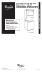
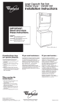
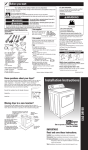
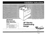
A
WARNING
. ALL RANGES CAN
TIP
. INJURY TO PERSONS
COULD RESULT
. INSTALLANTI-TIP
DEVICE PACKED
WITH RANGE
. SEEINSTALLATION
INSTRUCTIONS
-307563-02-O/4363 123
IMPORTANT:
Read and save
these instructions.
Important:
Installer: Leave Installation instructions with
the homeowner.
Homeowner:
Keep Installation Instructions
for future reference.
Save Installation Instructions for local
electrical inspector’s use.
30” Gas
Downdraft
Slide-in
Range
with self-cleaning
oven s
Before you start...
Check location where range will be
installed. The location should be
away from strong draft areas, such
as windows, doors, and strong
heating vents or fans, The range
should be located for convenient
use in the kitchen. Recessed
installations must provide complete
enclosure of the sides and rear of
range.
Proper installation is your responsibility.
A qualified technician
should install
this range. Make sure you have
everything
necessary for correct
installation. It is the responsibility of the
installer to comply with the installation
clearances
specified on the
serial/rating
plate. The serial/rating
plate is located on the oven frame
behind the door.
For minimum
clearances
see Note.“’
I
/-
I
1
/
openfng
*+* NOTE: JO” min. when bottom of
wood or metal cabinet is
protected
by not less than l/4”
flame retardant millboard
covered with not less than No. 28
MSG sheet steel, 0.015” stainless
steel, 0.024” aluminum or 0.020”
copper.
~tK%Ex~
width
18” min
clearance
upper cabinet
cooktoo to vertical wall or
other combustible
material.
36” min. clearance
between the
top of the cooking platform and
the bottom of an unprotected
wood or metal cabinet.
Island or peninsula installations
use 24” deep, flush back base
cabinets with no rear toe space.
If rear toe space is desired, use
27” or deeper base cabinet.
Important:
Observe all
governing codes
and ordinances.
Gas line can be
located through the
floor or through the
wall within this
shaded area.
-floor gc,
line openingif directly below
Do Not pinch
power !supply
between the
and the floor
Grounded electrical
outlet is required.
See
Electrical requirements.
Proper gas supply
connection
must be
available.
See Gas supply
requirements.
the
cord
range
or wall.
Oven frame must
extend beyond
cabinet fronts by
NOTE: Clearances
specified are for
combustible
walls and materials that
have a density of 20 or more pounds
per cubic foot. No evaluation
of
clearances
has been made for
installations adjacent to materials
that are less than 20 pounds per cu.
ft. or to plastic tiles and sheeting.
Make sure power cord
does not interfere
with exhaust ductwork.
Gas supply line piping
MUST NOT interfere
with vent ductwork.
Do Not seal
1:; Fd”,9’ to
WARNING: If the information
in this manual is not
followed exactly, a fire or
explosion may result
causing property damage,
personal injury or death.
- Do Not store or use gasoline
or other flammable vapors
and liquids in the vicinity of
this or any other appliance.
- WHAT TO DO IF YOU SMELL
GAS
l Do Not try to light any
appliance.
l Do Not touch
any electrical
switch; Do Not use any
phone in your building.
l Immediately
call your gas
supplier from a neighbor’s
phone. Follow the gas
supplier’s instructions.
l If you cannot
reach your
gas supplier, call the fire
department.
- Installation and service must
be performed by a qualified
installer, service agency or
the gas supplier.
W/idth -
29-15/16”
cabinets,
ALL OPENINGS IN THE WALL
OR FLOOR WHERE RANGE IS
TO BE INSTALLED MUST BE
SEALED.
l
l
Fire Hazard
Do Not obstruct the flow of
combustion
and ventilation
air.
Personal Injury Hazard
Avoid installing cabinet storage
above the cooking surface. If
cabinets are already installed,
reduce the hazard of reaching over
a heated cooking surface by
installing a range hood. The range
hood should extend a minimum of 5
inches out from the bottom front of
the cabinets.
Reaching over a heated cooking
surface could result in a serious burn.
Electrical Shock Hazard
It is the customer’s responsibility:
To contact a qualified electrical
installer.
To assure that the electrical
installation
is adequate
and in
conformance
with National
Electrical Code, ANSI/NFPA 70 latest edition*, and all local codes
and ordinances.
Failure to do so could result in fire,
electrical
shock or other personal
injury.
Tools needed for
installation:
caulking gun
duct tape
metal snips
hand or electric drill
wood floors: 3/32” drill bit
concrete/ceramic
floor: 3/16”
masonry
Copies of standards listed may be
obtained from:
National Fire Protection Association
Batterymarch
Park
Quincy, Massachusetts
02269
* American Gas Association
15 15 Wilson Boulevard
Arlington, Virginia 22209
l
drill bit
T
The anti-tip bracket MUST
be installed. For detailed
instructions, see Panel D.
Gas supply
requirements
Observe all governing
ordinances.
l
\
duct taoe
codes
and
Fire Hazard
b Range must be connected
to a
regulated gas supply. This must be
checked
by a qualified technician
before installing range.
mDo Not use an open flame to test
for leaks from gas connections.
New, A.G.A. design-certified
flexible gas line should be used
when codes permit.
Failure to follow these instructions
could result in a fire, explosion or
personal injury.
A
n
This installation must conform
with local codes and ordinances.
In
the absence of local codes,
installation must conform with
American National Standard, National
Fuel Gas Code ANSI 2223.1 - latest
edition”+.
B
l
Panel A
Cabinet opening dimensions
that are shown must be used.
Given dimensions are
minimum clearances
and
provide required 0”
clearance.
n
Input ratinqs shown on
the serial/rating
plate are for
elevations up to 2,000 feet. For
elevations above 2,000 feet, ratings
are reduced at a rate of 4% for each
1.000 feet above sea level.
C
This range is equipped
for use
with NATURAL gas only and is designcertified by A.G.A.
n
Electrical
requirements
Ductwork needed
is not included.
D
n Provide a gas supply line of
3/4” rigid pipe to the range location.
A smaller size pipe on long runs may
result in insufficient gas supply. Pipejoint compounds
made for use with
NATURAL and L.P. gas must be used.
E
n If local codes permit, A.G.A.
design-certified
flexible metal tubing is
recommended
for connecting
this
range to the gas supply line. Do Not
kink or damage the flexible tubing
when moving the range. A l/2” male
pipe thread is needed for connection
to pressure regulator female pipe
threads,
Electrical
F
n
The supply line shall be
equipped
with an approved
shutoff
valve. This valve should be located in
the same room as the range and
should be in a location that allows
ease of opening and closing. Do Not
block access to shutoff valve.
If rigid pipe is used as
supply line, a combination
of
fittings must be used to obtain
line connection
to the range.
strains must be removed from
supply and fuel lines so range
level and in line.
n
a gas
pipe
an inAll
the
will be
H
n The aas supplv pressure for
checking the regulator’setting
is to be
at least 7” W.C.(natural
gas),
Maximum supply pressure for Natural
Gas must not exceed 14” W.C. in
accordance
with a regulator setting
of 6” W.C.
I
n
Line pressure testing:
Testing above
l/2 psi (gauge)
The range and its individual shutoff
valve must be disconnected
from the
gas supply piping system during any
pressure testing of that system at test
pressures in excess of l/2 psig (3.5
kPa).
Testing at l/2 psi (gauge)
The range must be isolated from the
gas supply piping system by closing its
individual manual shutoff valve during
any pressure testing of the gas supply
piping system at test pressures equal
to or less than l/2 psig (3.5 kPa).
b Electrical ground is required on this
appliance.
B If cold water pipe is interrupted
by
plastic, non-metallic
gaskets or
other insulating materials, Do Not
use for grounding.
B Do Not ground to a gas pipe.
n Do Not modify the power supply
cord plug. If it does not fit the
outlet, have a proper outlet
installed by a qualified electrician.
mDo Not have a fuse in the neutral or
grounding circuit. A fuse in the
neutral or grounding
circuit could
result in an electrical
shock.
mDo Not use an extension cord with
this appliance.
b Check with a qualified electrician
if
you are in doubt as to whether the
appliance
is properly grounded.
Failure to follow these instructions
could result in serious injury or death.
A 120-volt, 60-Hz, AC-only, 15ampere,
fused electrical supply is required.
A
time-delay
fuse or circuit breaker is
recommended.
It is recommended
that a separate circuit serving only this
appliance
be provided.
Fire Hazard
0 Venting system must terminate to
the outside.
l Do Not terminate
the ductwork in
an attic or other enclosed space.
l
Do Not use 4” laundry-type
wall
caps.
Failure to follow recommended
venting instructions may result in a
fire.
Determine which venting method to
use. Ductwork can extend either
through the rear wall, left side or floor.
All transitions and ductwork needed
to vent to rear of range are supplied
with range. To vent through the floor,
use floor vent kit supplied.
To vent to
left side of range, a separate venting
kit (Kit No. 4315772) must be used and
is available from your dealer or
authorized
parts distributor.
The length of the ductwork and
number of elbows should be kept to a
minimum to provide efficient
performance.
The size of the
ductwork should be uniform. Do Not
install two elbows together.
Use duct
tape to seal all joints in the duct
system. Use caulking to seal exterior
wall or floor opening around cap.
Figures 2 - 7 show common venting
methods and types of materials
needed.
Electronic ignition systems operate
within wide voltage limits, but proper
grounding
and polarity are necessary
In addition to checking that the outlet
provides 120-volt power and is
correctly grounded,
the outlet must
be checked by a qualified electrician
to see if it is wired with correct polarity.
Flexible ductwork is Not
recommended.
If it is used, calculate
each foot of flexible ductwork as two
feet of straight metal ductwork.
Flexible elbows count twice as much
as standard elbows. Use metal
ductwork only.
The wiring diagram is included in the
literature package.
The wiring
diagram is also located on the
bottom of the storage drawer.
Use ductwork cutout dimensions
shown in Figures 2 - 7. If the ductwork
cutout location falls over a joist or
stud, a supporting frame must be
constructed.
Do Not cut joist or stud.
Recommended
grounding method
For personal safety, this appliance
must be grounded.
This appliance
is
equipped
with a 3-prong grounding
plug. To minimize possible shock
hazard, the cord must be plugged
into a mating 3-prong, groundingtype wall receptacle,
grounded
in
accordance
with the National
Electrical Code, ANSI/NFPA 70 latest edition”, and all local codes
and ordinances,
(See Figure 1.) If a
mating wall receptacle
is not
available,
it is the personal
responsibility and obligation
of the
customer to have a properly
grounded,
3-prong wall receptacle
installed by a qualified electrician.
NOTE: Make sure there is proper
clearance
within the wall or floor for
exhaust duct before making cutouts.
Rear wall venting installation
cabinet
rear w
transition
Figure 2
3-prong
grounding-type
wall receptacle
3-prong
grounding plug
Figure 1
Panel B
for left side venting
Shock Hazard
If codes permit and a separate
grounding wire is used, it is
recommended
that a qualified
electrician
determine that the grounding
path is adequate.
G
Venting
requfrkments
Figure 3
Floor venting installation
Recommended
Now start...
standard fittings
connects to
range exhaust +
With range in kitchen.
floor duct
1.
Q-
Remove racks and other parts from
inside oven. Remove venting kit from
storage drawer and remove elbow
taped to cardboard
base behind
storage drawer.
wall/floor
transition
3-l/4” x 10” 900
elbow=
=5R.
I
3-l/4” x 10” wall
cap=Oft.
3-l/4” x 10” flat
elbow = 12 ft.
I
I
I
Figure 4
6” duct system
cap
90” e
Maximum
Figure 5
Left side venting installation
length
Place one foot on the shipping base.
Tilt range forward slightly to free rear
legs. Gently lower range to floor. Tilt
range backwards
until front legs are
free.
= 18 feet
2-9O”elbow
1 -wall
cap
8 feet straight
= loft.
= Oft.
= 8ft.
Length of 6” system
= 18 ft.
3.
Remove shipping materials, tape and
protective
film from range. Do Not
remove cardboard
shipping base at
this time.
(Requires Kit No. 43 15772 available
from dealer.)
Recommended
2.
standard fittings
4.
Lower leveling legs approximately
l/4” or to a point where the range
base does not touch the floor.
connects to
range exhaust
5
Figure 6
I
I
Note: Never use laundry-type
I
wall caps.
I
Det:mine
side, rear
use. This
rear wall
If through
separate
ordered.
which venting method (left
wall, or floor) you need to
range is manufactured
for
or through the floor venting.
left side venting is desired, a
kit (Kit No. 4315772) must be
6.
nce
Figure 7
Recommended duct length
for island or peninsula
installations
Clearly mark where vent opening will
be made in cabinet opening
according
to the venting method
needed.
See Venting requirements
for dimensions.
7
Use 6” or 3-l /4” x 10” duct with a
maximum of 18 feet for duct system.
For best performance,
use no more
than three 90” elbows. To calculate
the length of system you need, add
the equivalent
feet for each duct
piece used in the system, See the
following example:
Usin:a saber saw, cut a 7-l /2” x
7-l /2” square opening for the vent
ductwork.
3- l/4” x 10” duct system
3-l/4”
elbow
x 10”
8.
For rear wall venting: Install wall/floor
transition through back of cabinet
using 8 wood screws (or anchor bolts
if fastening to drywall or masonry).
Stretch slotted gasket over edge of
wall/floor transition.
6” to 3-l/4”
transition
ET+-
Maximum
x 10”
length
90” elbow
1 -wall
cap
1 - transition
8- l/2 feet straight
Length of
3- l/4” x 10” system
Panel C
For countertops
without a backsplash,
the distance from the rear wall to the
gasket must be at least 3/4”;
7/8” maximum.
= 18 ft.
=
=
=
=
5ft.
Oft.
4-l/2
8-l/2
=18 ft.
ft.
ft.
10.
Use a pencil to mark the two mounting
screw hole locations on the anti-tip
bracket.
Remove bracket from
position.
Fire Hazard
Do Not make connection
too tight.
The regulator is die cast.
Overtightening
may crack the
regulator, resulting in a gas leak
and possible fire or explosion.
shim
Floor Damage
With
backsplash
Without
backsplash
For countertops
with a backsplash,
the distance from the rear wall to the
gasket must be at least 2-l /2”;
2-5/8” maximum.
All connections
tightened.
1 Contact a qualified floor covering
installer for the best procedure
to drill
mounting holes through your type of
floor covering.
) Before moving range across floor,
check that range is on shipping base
or slide range onto cardboard
or
hardboard.
Failure to follow these instructions may
result in damage to floor covering.
8a.
For floor or left side venting: Follow
instructions supplied with floor vent kit
or left side vent kit.
l/2” close nipple
l/2” nipple
1/\2” adapter
/
l/2” adapter
shutoff valve
pressure
regulator
17.
Attach wall duct to range fan exhaust
with wall duct directed toward rear of
range.
Secure wall/floor duct plate to wall
duct using screws supplied.
must be wrench-
Remove the storage drawer by lifting
slightly and pulling out of range.
Remove the regulator plug and
assemble the flexible connector
from
the gas supply to the pressure regulator
in order: manual shutoff valve, l/2”
nipple, l/2” adapter, flexible connector,
l/2” adapter, and l/2” close nipple.
11.
To mount antitip bracket to
wood floor, drill
a 3/32” hole at
each mounting
screw location.
To mount anti-tip bracket to concrete or
ceramic floor, use a masonry drill bit to
drill 3/l 6” holes at each mounting
screw location.
Tap plastic anchors into
mounting holes in floor with hammer.
12.
1 To prevent tipping, install the anti-tip
bracket.
1 Save these Installation Instructions.
If range is moved to a new location,
the anti-tip bracket must be
removed and reinstalled in the new
location.
9.
One anti-tip
bracket
must be installed,
l
Measure the
distance from
the center of the
leveling leg to
the furthest point
that extends
from the back of
the range.
3
I
18.
Pipe-joint compound
made for use with
NATURAL and L.P. gas must be used to
seal all gas connections.
Check that
the shutoff valve is open between the
regulator and gas valves. If flexible
connectors
are used, be certain
connectors
are not kinked.
13.
19.
Move range close to final position
Remove the shipping base, cardboard
or hardboard
from under the range.
Plug power supply cord into grounded
outlet.
Open shutoff valve in the gas supply
line. Wait a few minutes for gas to
move through the gas line.
14.
line
Mark on the floor the distance just
measured from the rear of the cabinet
opening or wall where the range will be
installed. Additional
space may be
needed for gas line located behind the
range.
l
_I
3L
line
l
Place one end of the anti-tip
bracket on the floor against the
cabinet side so that the inside edge
of the bracket is aligned with the line
drawn.
Note: If there is a cabinet on only one
side, the anti-tip bracket must be
installed against the cabinet.
Panel D
air shutter
Line up holes in
anti-tip bracket
with holes in
floor. Use the
screws provided
to fasten the
anti-tip bracket
to floor.
Carefully move range
into final position.
\
hai?
Remove storage
drawer or look
underneath
range. (A
flashlight may be needed.)
Check that
the rear leveling leg is engaged
in the
anti-tip bracket.
If leveling leg is not
properly engaged,
remove and
reposition the bracket to insure that the
leveling leg fits properly in the bracket.
Fire Hazard
Do Not use an open flame to test for
leaks from gas connections.
Checking for leaks with a flame may
result in a fire or explosion.
20.
15.
Place rack in oven. Place
level on rack, first side to
side; then front to back. If r
is not level, pull the range forward until
the rear leveling leg is removed from the
bracket.
Adjust the legs up or down
until range is level. Push range back
into position. Check that rear leveling
leg is engaged
in bracket.
Note: Oven must be level for
satisfactory baking conditions.
16.
Connect ductwork to range. Check
that power supply cord is not interfering
with duct work.
II II
Use a brush and liquid detergent
to test
all gas connections
for leaks. Bubbles
around connections
will indicate a leak.
If a leak appears, shut off gas valve
controls and adjust connections.
Then
check connections
again. NEVER TEST
FOR GAS LEAKS WITH A MATCH OR
OTHER FLAME. Clean all detergent
solution from range.
21.
Turn fan to “HI” to check that venting
gasket for rear wall or floor venting
properly seals wall/floor duct plate to
wall/floor transition.
If range does not
seal properly, contact a service
technician.
Replace storage drawer.
22.
Install grill and surface
burner modules.
Numbers
correspond
to steps.
Product Damage
Do Not insert any object
into the
openings of the protective
shield that
surrounds the ignitor.
Do Not clean the area.
Failure to follow these instructions
could result in product damage.
29.
24.
27
n
Check the oven burner for proper
flame. The flame should be l/2” long,
with inner cone of bluish-green,
an
outer mantle of dark blue and should
be clean and soft in character.
No
yellow tips, blowing or lifting of flame
should occur.
1
28
w
If oven flame needs to be adjusted,
loosen screw and adjust the air shutter
until the proper flame appears.
Tighten
screw. Replace oven bottom and oven
racks. Set the open area of the storage
drawer track down over the rollers on
both sides of the oven frame. Push
storage drawer back into place.
29.
Check the operation
of the oven broil
burner. Turn the oven selector knob to
“BROIL”. Push in and turn the oven
control knob to “BROIL” The oven broil
burner should light in 50 to 60 seconds.
This delay is normal. The oven safety
valve requires a certain time before it
will open and allow gas to flow.
Electronic Ignition System
Initial lighting and gas flame
adjustments.
Cooktop and oven burners use
electronic
ignitors in place of standing
pilots. When the cooktop control knob
is turned to the “LITE” position, the
system creates a spark to light the
burner. This sparking continues until the
control knob is turned to the desired
setting.
If oven control is turned to the desired
setting and sparks, the sparking will
continue until oven pilot ignites; then
the sparking stops automatically.
23
Check t:e
operation
of the
surface unit burners. Push in and turn
each surface unit control knob to ‘LITE”
position. The flame should light within 4
seconds. Do Not leave the knob in the
“LITE” position after burner lights.
24.
After burner lights, turn
control knob to the “HI”
position. Check each
surface unit burner for
proper flame. The small
inner cone should have a
very distinct blue flame l/4” to l/2” long,
The outer cone is not as distinct as the
inner cone.
Panel E
If burners
need
adjusting for
proper flame,
remove burner
grates and
carefully lift up
the module top. Adjust the air shutter
to the widest opening that will produce
a sharp blue flame that does not lift or
blow off the burner. Repeat as
necessary for each burner.
The low burner flame can be adjusted
by turning the adjustment
screw in the
center of the valve stem until a
minimum steady blue flame is
produced.
Turn the burner from high to
low several times to be sure that the
flame does not go out.
Reinstall module
26.
top and burner grates.
Check the operation
of the oven
burner. Remove oven racks and oven
bottom. Turn oven selector control knob
to ‘BAKE”. Push in and turn the oven
control knob to 300°F. The oven burner
should light in 50 to 60 seconds. This
delay is normal. The oven safety valve
requires a certain time before it will
open and allow the gas to flow,
30.
The flame should be l/2” long with an
inner cone of bluish-green
and an outer
mantle of dark blue. The flame should
also be clean and soft in character
with
no blowing or lifting of flame.
If the flame needs to be adjusted:
1. Remove the two screws fastening
the front of broil burner to the oven.
Pull the broil burner forward.
Loosen
the lock screw on the air shutter
located at the rear of the broil
burner.
2. Adjust the air shutter as needed.
Tighten the lock screw.
If you need setice...
If range does not
operate...
maintenance...
In the event that your Whirlpool appliance
should need service, call the dealer from
whom you purchased the appliance or a
Whirlpoolauthorized
service company.
A
Whirlpool-authorized
service company is
listed in the Yellow Pages of your
telephone directory under “Appliances Household - Major - Service or Repair”.
You can also obtain the service
company’s name and telephone number
by dialing, free, within the continental
United States, the Whirlpool Consumer
I&stance
Center telephone number,
(800) 253- 1301, A special operator will tell
you the name and number of your nearest
Whirlpool-authorized
service company.
Maintain the quality built into your
Whirlpool appliance - call a Whirlpoolauthorized service company.
If removing the range is necessary for
cleaning or maintenance,
shut off gas
supply to the range. Disconnect the gas
and electrical supply.
If the gas or electrical supply is
inaccessible,
lift the range slightly at the
front and pull the range out away from
the wall. Pull the range out only as far as
necessary to disconnect
the gas and
electric supply lines.
Remove the range to complete
cleaning or maintenance.
Move range back into operating
position. Level the range. Connect gas
line to range and check for leaks. Plug
electric power supply cord into outlet.
Make sure that the rear leveling leg is
engaged
in the anti-tip bracket.
Check that the circuit breaker is not
tripped or the house fuse blown.
l Check
that power supply cord is
plugged into wall receptacle.
Check
that gas supply is turned on.
l
If you need
assistance...
The Whirlpool Consumer Assistance
Center will answer any questions about
operating or maintaining your range not
covered in the Installation Instructions.
The Whirlpool Consumer Assistance
Center is open 24 hours a day, 7 days a
week. Just dial 1-@NJ) 253-l 301 - the
call is free.
When you call, you will need the range
model number and serial number. Both
numbers can be found on the
serial/rating plate located on the oven
frame behind the door.
NOTE:
Refer to Use and Care Guide for
operating
and cleaning
instructions.
Personal Injury/Product
Damage Hazard
Do Not step, lean or sit on the range
drawer or door.
Failure to follow this instruction could
result in personal injury and/or product
damage.
Part No. 36-307553XI2-0/4363
0 1993 Whirlpool Corporation
123
Prepared
by Whirlpool
Corporation,
Benton
Harbor,
Michigan
49022
Printed in U.S.A.