1
EXP1240 System Installation Guide
Revision 06
EXP1240 SIP DECT System:
Installation Guide
Revision 06, July 7, 2013
© Uniden America Corp., Irving, TX
CONFIDENTIAL AND PROPRIETARY
© 2013 Uniden America Corp.
PROPRIETARY AND CONFIDENTIAL
Page 1 of 71
EXP1240 System Installation Guide
Revision 06
Contents
Introduction .......................................................................................................................... 7
Important Safety Instructions! ..................................................................................................... 7
Check the Box Contents ...........................................................................................................................................7
About This Document ................................................................................................................... 8
Purpose and Audience .............................................................................................................................................8
Manual Conventions ................................................................................................................................................8
Terms used in this manual ....................................................................................................................................8
Hardware Setup .......................................................................................................................... 10
Base Station ...........................................................................................................................................................10
Connecting the Base Station ...............................................................................................................................10
Wall mounting the base station .......................................................................................................................... 12
Handset and Charger .............................................................................................................................................13
Charging the battery ...........................................................................................................................................14
Powering on the Handset....................................................................................................................................14
Initial System Configuration................................................................................................. 15
Using the Base Station Interface ................................................................................................ 16
Configuring General System Settings ......................................................................................... 17
Change Configuration and Management Settings .................................................................................................18
Change the Default Password ................................................................................................................................19
Change the PSTN Tones and Emergency Dialing ...................................................................................................19
Configure the Network Settings Screen .................................................................................................................20
Configure Time Settings ......................................................................................................................................21
Configuring the SIP Server Settings ............................................................................................ 22
To edit an existing server ....................................................................................................................................24
To delete a server ...............................................................................................................................................24
Program the SIP Extensions ...................................................................................................................................24
To edit an extension ............................................................................................................................................26
To delete extensions ...........................................................................................................................................26
Register Handsets to Extensions ............................................................................................................................26
To deregister a handset ......................................................................................................................................28
Multiple Base (Multi-cell) Systems ....................................................................................... 29
Introduction ................................................................................................................................ 29
Timing Levels..........................................................................................................................................................29
System Chain ID and RPN .......................................................................................................................................29
Setting Up a Multi-cell System ................................................................................................... 31
© 2013 Uniden America Corp.
PROPRIETARY AND CONFIDENTIAL
Page 2 of 71
EXP1240 System Installation Guide
Revision 06
Configuring the Primary Base Station .................................................................................................................... 32
Configuring Level 1 Base Stations ..........................................................................................................................33
Configuring Base Stations at Level 2 and Up .........................................................................................................36
Removing Base Station(s) from a Multi-Cell System ..............................................................................................37
Changing the Primary Base Station in a Chain .......................................................................................................38
System Maintenance ........................................................................................................... 40
Backing Up Configuration Settings ............................................................................................. 40
Restoring a Configuration ......................................................................................................................................41
Updating the Firmware .............................................................................................................. 41
Setting Up Firmware Folders .................................................................................................................................41
Valid server, folder, and firmware file name examples (base stations) ..............................................................41
Valid server, folder, and firmware file name examples (handsets) ....................................................................42
Configuring the Firmware Update Settings ...........................................................................................................42
Updating Base Station Firmware ...........................................................................................................................43
Updating Handsets.................................................................................................................................................44
To verify the firmware update ............................................................................................................................45
Appendix A: Software Reference ......................................................................................... 46
Base Station Configuration Interface ......................................................................................... 46
Available Screens ...................................................................................................................................................46
Global Buttons and Options ...................................................................................................................................47
Home/Status Screen (Read Only) .......................................................................................................................... 48
Extensions Screen ..................................................................................................................................................49
Add Extension and Edit Extension screens..........................................................................................................50
Servers Screen........................................................................................................................................................52
Network Screen .....................................................................................................................................................54
Management Screen ..............................................................................................................................................57
Firmware Update Screen .......................................................................................................................................59
Time Screen ...........................................................................................................................................................61
Country Screen.......................................................................................................................................................63
Web Security Screen ..............................................................................................................................................63
Central Directory Screen ........................................................................................................................................63
Multi Cell Screen ....................................................................................................................................................64
Configuration Screen (read only) ...........................................................................................................................68
Syslog Screen (read only) .......................................................................................................................................69
SIP Log Screen (read only)......................................................................................................................................70
Appendix B: RFPI Numbers .................................................................................................. 71
© 2013 Uniden America Corp.
PROPRIETARY AND CONFIDENTIAL
Page 3 of 71
EXP1240 System Installation Guide
Revision 06
Table of Figures
Figure 1 Base station front view ................................................................................................... 10
Figure 2 Base station rear view..................................................................................................... 10
Figure 3 Connecting the base station ........................................................................................... 11
Figure 4: Base mounting dimensions ............................................................................................ 12
Figure 5: Handset front view ........................................................................................................ 13
Figure 6: Charger top view ............................................................................................................ 13
Figure 7: Installing the handset battery........................................................................................ 14
Figure 8: Inserting the handset into the charger .......................................................................... 14
Figure 9: Home/Status screen .................................................................................................... 17
Figure 10: Management screen ................................................................................................... 18
Figure 11: Web Security screen .................................................................................................. 19
Figure 12: Country screen............................................................................................................ 20
Figure 13: Network screen........................................................................................................... 20
Figure 14: Time Settings screen ................................................................................................. 21
Figure 15: Checking time settings updates ................................................................................... 22
Figure 16: Servers screen ............................................................................................................. 22
Figure 17: Add Extension screen ................................................................................................ 25
Figure 18: Extensions screen, no handsets registered ................................................................ 27
Figure 19: Extensions screen, one handset registered ............................................................... 27
Figure 20: Extensions screen, three handsets registered ........................................................... 28
Figure 21: Sample multi-cell system ............................................................................................. 30
Figure 22: Multi-cell screen (default values) .............................................................................. 32
Figure 23: Home/status screen (primary base enabled) ............................................................ 33
Figure 24: Multi-cell screen after configuration ......................................................................... 34
Figure 25: Base Station Group table, synchronizing (Multi-cell screen) ................................. 34
Figure 26: Base Station Group table, synchronization complete (Multi-cell screen) ............. 35
Figure 27: Base Station Group table, Level 1 complete (Multi-cell screen) ............................ 36
Figure 28: Base Station Group table, Level 2 added (Multi-cell screen) ................................. 37
Figure 29: Configuration screen ................................................................................................. 40
© 2013 Uniden America Corp.
PROPRIETARY AND CONFIDENTIAL
Page 4 of 71
EXP1240 System Installation Guide
Revision 06
Figure 30: Firmware Update server information ....................................................................... 42
Figure 31: Firmware Update screen .......................................................................................... 43
Figure 32: Firmware update progress (Extensions screen) ......................................................... 45
List of Tables
Table 1: Terms................................................................................................................................. 9
Table 2: Abbreviations .................................................................................................................... 9
Table 3: Base station LEDs and their meanings ............................................................................ 11
Table 5: Summary: Basic system configuration ............................................................................ 16
Table 5: Sample multi-cell system information ............................................................................ 31
Table 6: Summary: Multi-cell system configuration ..................................................................... 31
Table 7 Firmware path examples.................................................................................................. 42
Table 8: Home/Status Options.................................................................................................... 48
Table 8: Home/Status parameters ............................................................................................. 48
Table 9: Extensions options......................................................................................................... 49
Table 10: Extensions parameters (read only) ............................................................................. 50
Table 11: Add extension and Edit extension parameters ........................................................ 51
Table 12: Servers options ............................................................................................................ 52
Table 13: Servers parameters ...................................................................................................... 52
Table 14: IP Settings parameters ................................................................................................ 54
Table 15: VLAN Settings parameters .......................................................................................... 55
Table 16: DHCP Options parameters .......................................................................................... 55
Table 17: NAT Settings parameters ............................................................................................ 56
Table 18: SIP/RTP Settings parameters ..................................................................................... 56
Table 19: Management Settings parameters ............................................................................ 57
Table 20: Firmware Update screen options............................................................................... 59
Table 21: Firmware Update Settings parameters .................................................................... 60
Table 22: Update Handsets parameters..................................................................................... 60
Table 23: Update Base stations parameters ............................................................................. 60
Table 24: Time Settings parameters .......................................................................................... 61
© 2013 Uniden America Corp.
PROPRIETARY AND CONFIDENTIAL
Page 5 of 71
EXP1240 System Installation Guide
Revision 06
Table 25: Settings for this unit parameters ............................................................................. 65
Table 26: DECT system settings parameters ............................................................................. 66
Table 27: Base station settings parameters.............................................................................. 66
Table 28: Base Station Group parameters................................................................................. 67
© 2013 Uniden America Corp.
PROPRIETARY AND CONFIDENTIAL
Page 6 of 71
EXP1240 System Installation Guide
Revision 06
Introduction
Important Safety Instructions!
When using your telephone equipment, basic safety precautions should always be
followed to reduce the risk of fire, electric shock and injury to persons, including the
following:
• This unit is NOT waterproof. DO NOT expose this unit to rain or moisture.
• Do not use this product near water, for example, near a bath tub, wash bowl, kitchen
sink or laundry tub, in a wet basement or near a swimming pool.
• Use only the power cord and batteries indicated in this manual.
• Do not dispose of batteries in a fire. They may explode. Check with local codes for
possible special disposal instructions.
• Do not place the handset in any charging cradle without the battery installed and the
battery cover securely in place.
SAVE THESE INSTRUCTIONS!
CAUTION! Risk of explosion if battery is replaced by an incorrect type!
Dispose of used batteries according to the instructions. Do not open or
mutilate the battery. Disconnect the battery before shipping this product.
For more details, see the Important Information section.
Check the Box Contents
If any items are missing or damaged, contact Customer Service immediately.
Never use damaged components!
© 2013 Uniden America Corp.
PROPRIETARY AND CONFIDENTIAL
Page 7 of 71
EXP1240 System Installation Guide
Base station box
– Base station
– Desk stand (attached)
– Wall mount hardware
– Important Safety Information
– Regulatory Information
Revision 06
Handset box
– Handset
– Charger and AC adapter
– Charger wall mount hardware
– Handset battery
– Belt clip
– Important Safety Information
– Regulatory Information
About This Document
Purpose and Audience
• This document describes the configuration, customization, management, operation,
maintenance and trouble shooting of the EXP1240 VoIP System.
• It is intended for use by system installers or integrators who have a background in
TCP/IP and SIP networks.
• Most of the procedures described in this document require administrator level access
to the EXP1240 base station.
• Each section of this document defines for only those fields necessary for that section.
Appendix A contains a complete list of screens and definitions of every field on each
screen.
Manual Conventions
This manual uses several different type styles to help you distinguish between different
parts of the system:
• Bold underlined text indicates a key on the unit itself or a button on a configuration
screen.
• Italicized type indicates text on the display, such as menu options, hyperlinks,
prompts, confirmation messages.
• ALL CAPS BOLD TYPE indicates a status light on the unit.
Terms used in this manual
This document uses the following terms and abbreviations:
© 2013 Uniden America Corp.
PROPRIETARY AND CONFIDENTIAL
Page 8 of 71
EXP1240 System Installation Guide
Revision 06
Table 1: Terms
Base station
The primary component of the system. The base station manages
connections with the SIP server or VoIP PBX and handles call control and
audio routing for handsets.
Handset
The end user’s main interface. The handset provides the user interface
and allows the end user to make and receive calls.
Charger
The handset cradle. The charger provides a slot to charge the handset
battery along with a slot for charging a spare battery.
Table 2: Abbreviations
CSV
Comma Separated Values
DHCP
Dynamic Host Configuration Protocol
DNS
Domain Name Server
HTTP(S)
Hyper Text Transfer Protocol (Secure)
(T)FTP
(Trivial) File Transfer Protocol
IP address
All IP addresses in this document are assumed to be IPv4 (i.e., in the
form XXX.XXX.XXX.XXX).
IPEI
International Portable Equipment Identity
G.711A
A-law Pulse Code Modulation
G.711U
mu-law Pulse Code Modulation
NTP
Network Time Protocol
PBX
SIP Server or VOIP PBX
PoE
Power over Ethernet
RFPI
Radio Fixed Part Identity
RPN
Radio Part Number
RSSI
Received Signal Strength Indication
RTP
Real-time Transport Protocol
RPORT
Response Port (Refer to RFC3581 for details)
SIP
Session Initiation Protocol
SME
Small and Medium scale Enterprise
© 2013 Uniden America Corp.
PROPRIETARY AND CONFIDENTIAL
Page 9 of 71
EXP1240 System Installation Guide
Revision 06
VLAN
Virtual Local Access Network
VOIP
Voice Over Internet Protocol
TOS
Type of Service (policy based routing)
URL
Uniform Resource Locator
UA
User Agent
Hardware Setup
Base Station
Figure 1 Base station front view
Figure 2 Base station rear view
Connecting the Base Station
If your network connection does not provide Power Over Ethernet, you will
need to order a standard Ethernet-to-PoE adapter. Contact customer
service.
© 2013 Uniden America Corp.
PROPRIETARY AND CONFIDENTIAL
Page 10 of 71
EXP1240 System Installation Guide
Revision 06
1) Connect a standard Ethernet cable (Cat 5 or higher) to the Ethernet/PoE jack on the
rear of the base station. Route the cable through the channel as shown below.
Figure 3 Connecting the base station
2) Connect the other end of the cable to your TCP/IP network.
When the base station powers on, the STATUS LED on the front briefly lights orange and
then turns off while it initializes and connects to the network. After the base station
successfully initializes and connects to the network, the LED lights green and remains
steady on.
Table 3: Base station LEDs and their meanings
Color
State
Meaning
Green
Flickering
Firmware update in progress
Green
Steady on
All operations normal.
(NA)
Off
No power in unit
OR
Initializing and connecting to the network.
Orange
Briefly on
Powering on
Orange
Flickering
Firmware update in progress
© 2013 Uniden America Corp.
PROPRIETARY AND CONFIDENTIAL
Page 11 of 71
EXP1240 System Installation Guide
Revision 06
Color
State
Meaning
Red
Blinking
Factory reset warning. A factory reset has been
initiated or is in progress.
Red
Blinking
No Ethernet connection available
OR
Handset registration failed.
Red
Briefly on
Reboot to start after firmware update.
Red
Flickering
Firmware update in progress.
Red
Steady on
Critical error. Contact technical support.
Wall mounting the base station
Figure 4: Base mounting dimensions
Be sure the wall
material can hold the
weight of the base.
1) Hold the base in its final
location and mark the
screw location based on
the measurements shown.
2) Insert the appropriate
anchors for the wall
material.
3) Insert the mounting
screws into the anchors,
leaving about ¼ inch of
space between the screw
head and the wall.
4) Connect the Ethernet
cable and route the cord
as shown.
5) Place the base over the
screw heads and slide it
down into place.
© 2013 Uniden America Corp.
PROPRIETARY AND CONFIDENTIAL
Page 12 of 71
EXP1240 System Installation Guide
Revision 06
Handset and Charger
Figure 5: Handset front view
Figure 6: Charger top view
© 2013 Uniden America Corp.
PROPRIETARY AND CONFIDENTIAL
Page 13 of 71
EXP1240 System Installation Guide
Revision 06
Charging the battery
1) Install the handset battery as shown below. (For more detailed instructions, see the End
User’s Guide.)
Figure 7: Installing the handset battery
Remove the battery
cover from the back
of the handset.
Insert the bottom of the battery into the
compartment. Lay the battery down and
push it gently until it snaps into place.
2)
Use the charger AC adapter to connect the
charger's AC jack to a standard 120V AC power
outlet.
3)
Place the handset in the charger with the display
facing forward. The HANDSET STATUS LED should
turn on; if it doesn’t, reseat the handset or try
plugging the AC adapter into a different outlet.
4)
Place the spare battery (if available) in the back
section of the charger; the BATTERY STATUS LED
should turn on. (Pull the battery latch back
slightly to fit the battery in the slot.)
Replace the battery
cover and slide it up
into place.
Figure 8: Inserting the handset
into the charger
Charge each battery completely (about 10
hours) before using it.
Powering on the Handset
To power up the handset, press End. The handset searches for the base station or multicell chain it is registered to and connects to the unit with the strongest signal.
To power down the handset, press and hold End until the display turns off (about 4
seconds).
© 2013 Uniden America Corp.
PROPRIETARY AND CONFIDENTIAL
Page 14 of 71
EXP1240 System Installation Guide
Revision 06
Initial System Configuration
This guide assumes that the EXP1240 system will be installed in a network environment
where the following servers are already installed and functioning:
• SIP server/VoIP PBX
• DHCP server
• NTP server
• TFTP server. This server must contain the following folders:
∘ LOG: for SIP log files. Base stations must be able to write to this folder which
should be created in the TFTP server’s working directory.
∘ {firmware path}: for firmware update files (see Setting Up Firmware Folders,
page 41)
• Syslog server. Base stations must be able to write to this server.
• DNS server Only required if you are using host names to access network nodes
There are some general server and base station requirements:
• The SIP server/VoIP PBX, NTP, and Syslog servers must be available at all times.
• If the base stations acquire their IP addresses dynamically (rather than being
statically assigned), then the DHCP server must be available at all times.
• The TFTP server must be available for firmware updates and SIP log uploads.
• All base stations must be on the same subnet.
• Servers can reside on the same machine.
Table 4 shows a top-level summary of the steps needed to configure the base station to
operate in a single-cell system. You will use these same steps to configure the first base
station in a multi-cell system.
© 2013 Uniden America Corp.
PROPRIETARY AND CONFIDENTIAL
Page 15 of 71
EXP1240 System Installation Guide
Revision 06
Table 4: Summary: Basic system configuration
Step
Screens used Notes
General System Settings
1. Change the name that appears at the top
of the configuration screens, specify a
Management Required
configuration server, and enable SIP and
system logs.
2. Change the default user name and
password.
Web Security Recommended
3. Change the PSTN tones and emergency
dialing format.
Country
Required for countries other
than the US and Canada
4. Configure basic network settings.
Network
Required
Time
Settings
Required (If you are updating
Server information, you must
reboot the base station for
changes to take effect.)
6. Program the SIP server(s).
Network
Servers
Required (You must reboot the
base station for changes to
take effect).
7. Program extensions on each SIP server.
Extensions
Required
8. Register a handset to each extension.
Extensions
Required
5. Specify time server address and DST
settings.
SIP Server Settings
Using the Base Station Interface
Each base station has a built-in HTTP server that controls the configuration interface. To
open the web page:
1) Open a web browser window and type the IP address of the base station in the address
bar. If you don't know the base station's IP address, try one of the following:
∘ Use the IP Search function on the handsets. On any handset, press Menu (
), then enter *47* (*IP*). After several seconds, the handset displays the
MAC and IP addresses of all base stations within range. Find the MAC
address of the base station in the list to determine its IP address. To exit IP
Search, press End ( ) twice.
© 2013 Uniden America Corp.
PROPRIETARY AND CONFIDENTIAL
Page 16 of 71
EXP1240 System Installation Guide
Revision 06
∘ If your network supports Dynamic DNS, then type ipdect<{MAC}> in the
address bar of your browser (just insert the MAC address of the base station
in place of {MAC} ).
2) Enter the user ID and password. The default user ID and password are both admin (all
lower case). The base station opens the Home/Status screen.
Figure 9: Home/Status screen
• You can open any configuration screen by clicking its name on the left side of the
screen; the screen name links appear on every screen.
Configuring General System Settings
This document does not cover general IP and SIP network setup. If you need
more information on the necessary settings for your servers, contact your
network administrator.
© 2013 Uniden America Corp.
PROPRIETARY AND CONFIDENTIAL
Page 17 of 71
EXP1240 System Installation Guide
Revision 06
Change Configuration and Management Settings
1) In the left panel of the screen, select Management. This opens the Management screen.
Figure 10: Management screen
2) In the Base Station Name field, enter the title you want to appear in the configuration
screens for this base station. (This will help you verify that you have logged into the
correct base station in the future.) The title can be any HTML-readable text string.
3) In the Configuration server address field, enter the IP address or URL of the server that
hosts SIP log files (this is usually your TFTP server). The base station will also copy its
debug files to this sever. The TFTP Server must be running for SIP log file uploads.
4) Under Management Transfer Protocol, select TFTP.
5) HTTP management is reserved for system development; just ignore these fields.
6) If you want to have this base station copy SIP messages onto the configuration server,
select Enabled in the Upload of SIP Log field. SIP logs are named in the format of
{MAC_address}_SIP_{timestamp}.log (Unless you’re troubleshooting a specific problem,
you should leave this disabled.)
7) Trace server information is reserved for system development; just ignore these fields.
8) To have this base station copy system log messages onto a system log server, enter the
IP address of the server in the Syslog Server IP Address field. (If your syslog server is
listening to a port other than the default, enter that port number in System Syslog Port.)
Then, in the Syslog Level field, select one of the following:
∘ Off: no system events are logged.
© 2013 Uniden America Corp.
PROPRIETARY AND CONFIDENTIAL
Page 18 of 71
EXP1240 System Installation Guide
Revision 06
∘ Normal Operation: This will output normal operation event logs targeted for
an administrative audience. Event logs included are incoming call, outgoing
call, handset registration, DECT location, firmware updates, call lost due to
busy, critical system errors, and general system information. Select this level
during system configuration unless requested by a technician to select one
of the other levels.
∘ System Analyze: This will output normal operation event logs plus more
technical logs. This level of logging is targeted for a level 1 or 2 tech support.
∘ Debug: This will output the previous two types of logs plus lower level logs
whose audience are system developers. Please be aware that enabling this
level of logging will degrade system performance.
9) Click Save when you’re finished.
Change the Default Password
In the left panel of the Home/Status screen, select Web Security. This opens the Web
Security screen. Enter a new username and password, then click Save.
Figure 11: Web Security screen
Be sure to keep track of the new user name and password according to your
organization’s procedures.
Change the PSTN Tones and Emergency Dialing
If the system connects to the PSTN in the US or Canada, skip this section.
1) In the left panel of the Home/Status screen, select Country. This opens the Country screen.
© 2013 Uniden America Corp.
PROPRIETARY AND CONFIDENTIAL
Page 19 of 71
EXP1240 System Installation Guide
Revision 06
Figure 12: Country screen
2) Select the country that best represents the PSTN standards the system should use.
3) Click Save & Reboot. When the base station finishes rebooting, the interface will use
the new language.
Configure the Network Settings Screen
1) In the left hand panel, select Network. This opens the Network screen.
Figure 13: Network screen
© 2013 Uniden America Corp.
PROPRIETARY AND CONFIDENTIAL
Page 20 of 71
EXP1240 System Installation Guide
Revision 06
2) Enter the correct settings for your network and click Save. Refer to Appendix A:
Software Reference on page 46 if you need more information on these fields.
Normally, you need to reboot the base station to activate new network settings.
However, during initial configuration, wait until you configure the rest of the screens
before rebooting. (Changing the Time Settings, for instance, will force a reboot.)
Configure Time Settings
1) In the left hand panel, select Time. This opens the Time Settings screen.
Figure 14: Time Settings screen
2) In the Time Server field, enter the IP address or URL of the server that distributes
reference clock information for your network. This server must be visible to the base
stations at all times.
3) In the Time server refresh interval field, change the number of hours the base should
wait before it checks the time server again (if necessary).
4) In the Timezone field, select the number of hours the local time zone differs from
GMT/UTC time. For example, US Central Standard Time (CST) is 6 hours behind UTC, so
you would set the Timezone field to −6:00.
5) Enter any necessary settings for Daylight Savings Time, then click Save & Reboot. (If
you need more information on these fields, refer to Appendix A: Software Reference on
page 46.)
© 2013 Uniden America Corp.
PROPRIETARY AND CONFIDENTIAL
Page 21 of 71
EXP1240 System Installation Guide
Revision 06
6) After the base station reboots, verify the time settings updates.
∘ Check the Home/Status screen to be sure the time has updated correctly.
∘ Check the Time screen to verify that the time server IP address is still
correct.
Figure 15: Checking time settings updates
Configuring the SIP Server Settings
1) If necessary, go to the Network screen (Figure 13) and verify that the parameters under
the SIP/RTP Settings are correct.
2) In the left panel of the screen, select Servers. This opens the Servers screen.
Figure 16: Servers screen
3) Click Add Server, then enter the necessary information for the first SIP server.
© 2013 Uniden America Corp.
PROPRIETARY AND CONFIDENTIAL
Page 22 of 71
EXP1240 System Installation Guide
NATAdaption
Revision 06
Selecting YES indicates If information in “rport” and “received”
parameters is different from local information. Base will perform new
SIP registration with the new information in “Contact” header. If
information in “rport and “received” parameters is not different from
local information then no action is performed.
Selecting NO means the Base Station disregards information from the
“rport” and “received” parameters.
SIP Server
Enter the IP address of the SIP server. If desired, you can add the port
number after the IP address using the format {IPaddress}:{port} (e.g.,
192.168.250.111:5080).
If there is a SIP Proxy, between the base station and the SIP server, enter
the IP address of the SIP Proxy. If desired, you can add the port number
Outbound Proxy
after the IP address using the format {IPaddress}:{port} (e.g.,
192.168.250.111:5060).
Re-registration
time
Enter the number of seconds that will determine the frequency of
handset re-registrations with the SIP Server. If the number of seconds is
less than 600, then the frequency will be half of the number of seconds.
If the number of seconds is 600 or greater, then the frequency will be
the value minus 300 seconds. As examples, if the entered number of
seconds is 500, then the re-registration frequency will be 500/2 = 250
seconds. If the number of seconds is 700, then the re-registration
frequency will be 700 – 300 = 400 seconds.
DTMF Signalling
Select the type of DTMF signalling used by the SIP server:
– SIP INFO: DTMF tones are sent out of band along the SIP signalling
path.
– RFC 2833: DTMF tones are sent via data packets in a different
internet layer than the voice stream.
– Both: DTMF tones are sent both in the SIP signalling path (SIP INFO
mode) and via data packets (RFC 2833 mode).
Codec Priority
Set the priority order of the voice codecs in use by the SIP server. The
base station will use the codecs in the order they appear in the list. To
change the priority of the codecs, select a codec and click one of the
following:
– Up: move the selected codec up the priority list.
– Down: move the selected codec down the priority list.
– Reset: restore the default codec list.
– Remove: remove the selected codec from the list (the base station
will not use this codec).
© 2013 Uniden America Corp.
PROPRIETARY AND CONFIDENTIAL
Page 23 of 71
EXP1240 System Installation Guide
Revision 06
4) When you're finished, click Save. The new server and its IP address are added to the list
on the left.
5) Repeat this process for each SIP server you want to configure for this system.
To edit an existing server
1) In the list of servers, click on server you want to edit. The parameters for that server are
loaded into the screen.
2) Edit the parameters you want to change, then click Save,
OR click Cancel to leave the server parameters unchanged.
3) Reboot the base station for the edits to take effect.
To delete a server
1) In the list of servers, click on the server you want to delete. The parameters for that
server are loaded into the screen.
2) Click Remove Server.
Deleting a SIP server will delete any extensions associated with the server,
deregistering them from the server if necessary.
Program the SIP Extensions
• Before you program the extensions, you must have at least one SIP server assigned to
this base station.
• An extension will not become active until the extension is programmed in the SIP
Server and you register a handset to the extension.
1) In the left panel of the Home/Status screen, select Extensions. The base station opens the
Extensions screen and displays the extension information for Server 1.
2) If you have more than one SIP server, click the name of the server you want to program
extensions for.
3) Click Add Extension, then enter the parameters for this extension.
© 2013 Uniden America Corp.
PROPRIETARY AND CONFIDENTIAL
Page 24 of 71
EXP1240 System Installation Guide
Revision 06
Figure 17: Add Extension screen
Extension
Enter the handset phone number or SIP username as configured
on the SIP server or VoIP PBX.
Authentication User
Name and Password
Enter the name and password you use to register with the
selected SIP server.
Display Name
Enter the name of this extension (up to 10 characters). This
name is used for reference on the web interface.
Mailbox Name
Enter the name of the voice mailbox this extension should use.
Server
Select the SIP server this extension is programmed on.
Forwarding
Unconditional Number
Forward all calls: Enter the number the system should forward
calls to. Select Enable to turn call forwarding on or Disable to
leave it off.
Forwarding No Answer
Number
Forward on no answer: Enter the number the system should
forward calls to when this extension does not answer, then
enter the number of seconds you want the system to wait in the
field to the right. Select Enable to turn call forwarding on or
Disable to leave it off.
Forwarding on Busy
Number
Forward on busy: Enter the number the system should forward
calls to when this extension is busy. Select Enable to turn call
forwarding on or Disable to leave it off.
© 2013 Uniden America Corp.
PROPRIETARY AND CONFIDENTIAL
Page 25 of 71
EXP1240 System Installation Guide
Revision 06
4) Click Save when you’re finished.
5) Repeat the process for each extension you want to program for this server. To program
extensions for a different server, select the new server on the main Extensions screen.
To edit an extension
1) Click on the name of the extension in the list. The parameters for that extension are
loaded into the screen.
2) Edit the parameters you want to change, then click Save,
OR click Cancel to leave the extension parameters unchanged.
To delete extensions
3) Click the check box beside the extensions you want to delete.
4) Click Delete Extension(s). When the base station asks you to confirm, click OK,
OR click Cancel to leave the extension information in the base station.
When you delete an extension, any handset(s) registered to that extension
will be deregistered automatically.
Register Handsets to Extensions
In a multi-cell system, you can register the handsets to extensions from any
base station. When a handset is moved into another base station's range, it
will automatically update its registration to the new base station after 5 to 7
minutes.
1) On the Extensions screen, click the box beside the extension you want to register. (You
can only register one extension at a time.)
© 2013 Uniden America Corp.
PROPRIETARY AND CONFIDENTIAL
Page 26 of 71
EXP1240 System Installation Guide
Revision 06
Figure 18: Extensions screen, no handsets registered
2) Click Register Handset(s) to put the base station into registration mode. The base station
will remain in registration mode for 5 minutes.
3) On the handset, press Menu to open the menu screen.
4) Select Connectivity and then select Register.
5) When prompted, enter the base station registration Access Code. (The Access Code is
0000.)
6) Press the OK soft key to confirm.
7) Within a minute, the base station configuration screen will update with the new
information.
Figure 19: Extensions screen, one handset registered
8) Verify that the Extension and Display Name are correct and that the State shows SIP
Registered.
9) Make a quick test call to verify the handset is correctly registered.
10) Repeat the process for each extension.
© 2013 Uniden America Corp.
PROPRIETARY AND CONFIDENTIAL
Page 27 of 71
EXP1240 System Installation Guide
Revision 06
Figure 20: Extensions screen, three handsets registered
To deregister a handset
1) Click the check box beside the handset(s) you want to deregister.
2) Click Deregister Handset(s). When the base station asks you to confirm, click OK,
OR click Cancel to leave the handset registered to this extension.
© 2013 Uniden America Corp.
PROPRIETARY AND CONFIDENTIAL
Page 28 of 71
EXP1240 System Installation Guide
Revision 06
Multiple Base (Multi-cell) Systems
Introduction
To install a EXP1240 system with more than one base, you must configure it as a multicell system. This section explains how to configure multi-cell systems. For detailed
information on multi-cell operation and the difference between single and multi-cell
systems, see the Network Planning Guide.
Timing Levels
• In multi-cell systems, one base station serves as the primary synchronization source
for all the other base stations. This base station is considered at timing Level 0.
• Base stations at Level 1 get their timing directly from the primary base station. (These
must be in range of the primary base station.)
• Base stations at Level 2 get their timing from base stations at Level 1. Base stations at
Level 3 get their timing from base stations at Level 2, and so on.
• Level 6 is the maximum timing level.
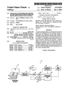
System Chain ID and RPN
To enable base stations to recognize members of the same system, each multi-cell
system requires a separate system chain ID number. All base stations that share a system
chain ID will function as part of the same multi-cell system.
Within the system chain, each base station is automatically assigned an RPN
identification number. When you select a synchronization source for each base station,
you will use the source's RPN to identify it.
• The system assigns the RPN based on the order in which the base stations are added
to the chain. For example, the first base station added to the chain (usually the
primary) is assigned an RPN of 00, the second base is assigned an RPN of 04.
• If you want the base stations to appear in a particular sequence, add the stations to
the chain in that order.
Figure 21 shows an example of a multi-cell system, and Table 5 summarizes the
parameters for this example. This information is used throughout the instructions.
© 2013 Uniden America Corp.
PROPRIETARY AND CONFIDENTIAL
Page 29 of 71
EXP1240 System Installation Guide
Revision 06
Figure 21: Sample multi-cell system
© 2013 Uniden America Corp.
PROPRIETARY AND CONFIDENTIAL
Page 30 of 71
EXP1240 System Installation Guide
Revision 06
Table 5: Sample multi-cell system information
Base Station
RPN (assigned by system)
Synchronization Source
Base #0
00
RPN 00 (self)
Base #1
04
RPN 00 (Base #0)
Base #2
08
RPN 00 (Base #0)
Base #3
0C
RPN 04 (Base #1)
Base #4
10
RPN 08 (Base #2)
Base #5
14
RPN 0C (Base #3)
Base #6
18
RPN 10 (Base #4)
Base #7
1C
RPN 10 (Base #4)
Setting Up a Multi-cell System
The table below shows a top-level summary of the steps needed to set up a multi-cell
system.
Table 6: Summary: Multi-cell system configuration
Step
Screens used
1. Place the primary base station at its final location.
NA
2. Configure the primary base station.
Multicell
3. Reboot the primary base station and verify the settings.
Home/Status
4. Place each Level 1 base station at its final location.
NA
5. Configure each Level 1 base station and reboot.
Multi-cell
Home/Status
6. Synchronize each Level 1 base station.
Multi-cell
7. Repeat the process with each Level 2 base station.
Multi-cell
Home/ Status
8. Repeat the process with any base stations at Level 3 through
Level 6.
Multi-cell
Home/Status
© 2013 Uniden America Corp.
PROPRIETARY AND CONFIDENTIAL
Page 31 of 71
EXP1240 System Installation Guide
Revision 06
Configuring the Primary Base Station
You will need to perform the following steps on the primary base station only. See page
33 for information on all other base stations.
1) Place the primary base station at its final location. (See the Network Planning Guide for
information on the proper placement of base stations.)
2) Login to the base station.
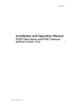
3) In the left hand panel, click on Multi cell. This opens the Multi-cell screen.
Figure 22: Multi-cell screen (default values)
4) Set the Multi cell system field to Enable.
5) In the System chain ID field, enter the unique identifier of the chain this base station
should belong to. Acceptable ID values range from 0 to 99999.
6) In the Synchronization time(s), change the number of seconds between each time this
base station re-synchronizes with the other base stations in this chain (if necessary).
© 2013 Uniden America Corp.
PROPRIETARY AND CONFIDENTIAL
Page 32 of 71
EXP1240 System Installation Guide
Revision 06
7) If you want the base station to log low level multi cell debug information in the System
Log, set the Multi cell debug field to Data Sync, Auto Tree, or Both. (This log contains a
large number of messages, so you should leave it disabled most of the time.)
8) Click Save, then reboot the base station (go back to the Home/Status screen and click
Reboot).
9) When the base station finishes rebooting, verify that the RFPI-Address on the
Home/status screen shows RPN:00 at the end of the field. After a few minutes, the System
Information field also updates to display the new status.
Figure 23: Home/status screen (primary base enabled)
Configuring Level 1 Base Stations
1) Place the first Level 1 base station at its final location.
2) Login to the base station.
3) Reset the base station to its default settings (open the Management screen and click
Default Base Station). If this base station has never been configured, skip this step.
4) Go to the Multi-cell screen and set the Multi cell system field to Enable.
5) Enter the System chain ID of the chain this base station should belong to.
6) If you want the base station to include low level multi cell debug information in the
System Log, set the Multi cell debug field to Data Sync, Auto Tree, or Both. (This log
contains a large number of messages, so you should leave it disabled most of the time.)
7) Click Save and reboot the base station (go back to the Home/Status screen and click
Reboot).
8) When the base station finishes rebooting, click Home, and after a few minutes, go back
to the Multi-cell screen. You will see that the System chain ID field is read-only, and the
DECT system settings and Base station settings fields, and the Base Station Group table are
added to the bottom of the screen.
© 2013 Uniden America Corp.
PROPRIETARY AND CONFIDENTIAL
Page 33 of 71
EXP1240 System Installation Guide
Revision 06
Figure 24: Multi-cell screen (top) after configuration
9) Keep the Auto configure DECT sync source tree set to Disabled.
10) In the Number of SIP accounts before distributed load field, enter the maximum number
of handset registrations (up to 30) for each base station. This number is synchronized
among all the bases in the chain, so you only have to enter it once.
11) Click Save.
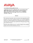
12) Use the Base Station Group table to check system synchronization.
Figure 25: Base Station Group table, synchronizing (Multi-cell screen)
© 2013 Uniden America Corp.
PROPRIETARY AND CONFIDENTIAL
Page 34 of 71
EXP1240 System Installation Guide
Revision 06
∘ The IP Status field of the base station you are logged into should show This
unit. Any other base stations in this chain should show Connected (i.e.,
connected to the network and functioning properly) as their IP status. If any
base station shows Connection Loss as its IP status, that base station is not
connected to the network or has lost power.
∘ The primary base station always serves as its own sync source, so the DECT
sync source field should display Primary:RPN{its own RPN}. The DECT
Property field shows Primary.
∘ This base station's DECT sync source will show (any) RPN and its DECT
Property field will show Locked.
∘ Check the DECT sync source drop-down box for this base station to verify
that there is a selection for the primary base station with a dBm value. If
there is not a dBm value, wait for the system to further synchronize
(approximately 2 minutes). When there is a dBm value, select the primary
base station from the DECT sync source drop-down box and click Save.
∘ If the primary base station is not on the list or if the signal strength is below 70 to -73 dBm (-74dBm or less), move this base station to a different
location. (You could also configure the other Level 1 base stations first and
then come back and configure this one at Level 2.)
∘ The DECT Chain appears at the bottom of the display and shows the
synchronization source for all base stations in this system. Until the primary
base station is selected as the DECT sync source, there will be a warning in
the DECT Chain for this base station.
Figure 26: Base Station Group table, synchronization complete (Multi-cell screen)
13) When the system has finished synchronizing, repeat this process for each base station at
Level 1.
© 2013 Uniden America Corp.
PROPRIETARY AND CONFIDENTIAL
Page 35 of 71
EXP1240 System Installation Guide
Revision 06
Figure 27: Base Station Group table, Level 1 complete (Multi-cell screen)
Configuring Base Stations at Level 2 and Up
1) Place the first Level 2 base station at its final location. (See the Network Planning Guide
for information on the proper placement of base stations.)
2) Login to the base station.
3) Reset the base station to its default settings (open the Management screen and click
Default Base Station). If this base station has never been configured, skip this step.
4) Go to the Multi-cell screen and set the Multi cell system field to Enable.
5) Enter the System chain ID and select a Multi Cell debug setting only if necessary.
6) Click Save and reboot the base station.
7) Allow several minutes for the base station to reboot, then go back to Multi-cell screen
and check the Base Station Group table.
© 2013 Uniden America Corp.
PROPRIETARY AND CONFIDENTIAL
Page 36 of 71
EXP1240 System Installation Guide
Revision 06
Figure 28: Base Station Group table, Level 2 added (Multi-cell screen)
∘ Select a synchronization source for this base station in the DECT sync source
list (usually, this is the base station with the strongest signal). Wait until this
base station locks onto the synchronization source, then click Save.
∘ In the DECT Chain, this base station will appear under its synchronization
source.
8) When the system has finished synchronizing, repeat this process for each base station at
Level 2.
9) After you’ve configured all the base stations at Level 2, follow the same procedure for
the base stations at Level 3, Level 4, and so on, until all base stations have been added to
the system.
Removing Base Station(s) from a Multi-Cell System
Before removing the primary base station from the system, configure a
different base station to be the primary synchronization source (see page 38).
Never default or remove a base station from a chain with an ID of 0 (or
RPN00), or the chain will have to be rebuilt.
1) Login to a base station other than the one you want to remove from the system.
2) Go to the Multi Cell screen and view the Base Station Group table. Note the RPN number
of the base station to be removed.
© 2013 Uniden America Corp.
PROPRIETARY AND CONFIDENTIAL
Page 37 of 71
EXP1240 System Installation Guide
Revision 06
3) Check the Extensions screen to see if any extensions are registered to the base station to
be removed. The State column displays which base station the handset extensions are
registered.
4) Physically move the handsets registered to those extensions out of this base station's
coverage area and place them next to a different base station. Wait for the handsets to
change their registration to the new base station. Alternatively, power off the handsets,
and power them on near the different base station.
5) In the Base Station Group table, check to see if the base station you want to remove is
serving as the synchronization source for any other base station(s). If necessary, select a
new DECT sync source for any affected base stations, and click Save.
6) Click the check box beside the base station you want to remove from this chain, then
click Remove from chain. (Be sure you do not check the base station with ID 0/RPN00.)
7) Login to the base station just removed. On the Home/Status screen, verify that it reads
Multi Cell disabled on the System Information line
8) For use in another chain, reset the base station to its factory default settings (go to the
Management screen and click Default Base Station).
∘ When the base station finishes rebooting, login and check the Home/Status
screen. The base station name at the top of the screen should read SME VoIP
and the System Information field should still read Multi cell Disabled.
9) Log out of the base station, and repeat this procedure on any other base stations you
want to remove from system.
Changing the Primary Base Station in a Chain
Only perform this procedure when the system is offline or in a maintenance
period.
1) Log in to a base station in the chain.
2) Go to the Multi Cell screen.
3) In the Base Station Group table, determine which base station you want to become the
new primary base station.
4) Select this base station's own RPN as the DECT Sync Source.
5) For the original Primary base station, select the new Primary or another base station
within its range as its DECT Sync Source .
6) Click Save.
7) Login to the original primary base station, and go to the Multi Cell screen.
8) Click Reboot.
© 2013 Uniden America Corp.
PROPRIETARY AND CONFIDENTIAL
Page 38 of 71
EXP1240 System Installation Guide
Revision 06
9) After reboot, on the Home/Status screen, verify that it reads Multi cell Ready (Keep-alive)
Secondary.
10) Login to the new primary base station. On the Home/Status screen, verify that it reads
Multi cell Ready (Keep-alive) Primary.
11) Go to the Multi Cell screen. Check the Base Station Group table and verify that all base
stations have properly resynchronized.
© 2013 Uniden America Corp.
PROPRIETARY AND CONFIDENTIAL
Page 39 of 71
EXP1240 System Installation Guide
Revision 06
System Maintenance
Backing Up Configuration Settings
1) Configure the first base station completely and save the configuration.
2) In the left hand panel, click on Configuration. This opens the Configuration screen.
Figure 29: Configuration screen
3) At the top of the screen, click Save.
4) Save the file with a .cfg extension to a designated location for managing base station
configuration settings.
© 2013 Uniden America Corp.
PROPRIETARY AND CONFIDENTIAL
Page 40 of 71
EXP1240 System Installation Guide
Revision 06
Restoring a Configuration
1) Login to the base station interface (see page 16), and go to the Configuration screen.
2) Click Browse and select the configuration file for this base station.
3) Click Load, then reboot the base station.
4) When the base station finishes rebooting, check the configuration settings to be sure
they loaded correctly.
Updating the Firmware
You can update the firmware on base stations and handsets remotely via TFTP.
Setting Up Firmware Folders
The TFTP server must be correctly configured before you can update the firmware on
any components, and folders and firmware filenames must use specific naming
conventions.
• The server must be identifiable by an URL or IP address (IPv4).
• The server must allow both transmitting and receiving on the firmware folder (so
base stations can upload copies of old firmware before updating).
• Folders in the firmware path must have or TFTP compatible names, e.g., they must not
contain spaces, question marks, colons, semicolons, commas, etc.
• In the firmware update path directory, create the directories Beatus (for base station
firmware files) and Pegasus (for handset firmware files)
• Place the new base and handset firmware files in their respective directories. The
name of the firmware file will be in the following format (where {version number} is
any 3-digit positive integer):
Base station files
Handset files
BeatusSW_4181_v0{version number}.fwu
PegasusSW_4181_v0{version number}.fwu
Valid server, folder, and firmware file name examples (base stations)
• tftp://update.abc.com/ipdect/firmware/Beatus/BeatusSW_4181_v0026.fwu
• tftp://abc.com/firmware_update/Beatus/BeatusSW_4181_v0001.fwu
• tftp://192.168.10.207/fwupdate/Beatus/BeatusSW_4181_v0010.fwu
© 2013 Uniden America Corp.
PROPRIETARY AND CONFIDENTIAL
Page 41 of 71
EXP1240 System Installation Guide
Revision 06
Valid server, folder, and firmware file name examples (handsets)
• tftp://update.abc.com/ipdect/firmware/Pegasus/PegasusSW_4181_v0019.fwu
• tftp://abc.com/firmware_update/Pegasus/PegasusSW_4181_v0007.fwu
• tftp://192.168.10.207/fwupdate/Pegasus/PegasusSW_4181_v0023.fwu
Configuring the Firmware Update Settings
Login to the base station interface (see page 16), and go to the Firmware Update screen.
Figure 30: Firmware Update server information
5) In the Firmware update server address field, enter the name or IP address of the TFTP
server.
∘ Enter the folder path between the server root and the Beatus or Pegasus
folder.
∘ Do not include the folder name for base stations (Beatus) or handsets or
(Pegasus): these are added automatically).
∘ This field must start with a forward slash (/).
∘ Do not include a forward slash at the end of the field.
∘ The table below shows how you would enter the server address and
firmware path using the examples shown on page 41.
Table 7 Firmware path examples
Firmware update
server address
Firmware path
Firmware
folder
Firmware file name
Base station firmware files
update.abc.com
/ipdect/firmware
/Beatus/
BeatusSW_4181_v0026.fwu
abc.com
/firmware_update
/Beatus/
BeatusSW_4181_v0001.fwu
192.168.10.207
/FWupdate
/Beatus/
BeatusSW_4181_v0127.fwu
© 2013 Uniden America Corp.
PROPRIETARY AND CONFIDENTIAL
Page 42 of 71
EXP1240 System Installation Guide
Revision 06
Handset firmware files
update.abc.com
/ipdect/firmware
/Pegasus/
PegasusSW_4181_v0019.fwu
abc.com
/firmware_update
/Pegasus/
PegasusSW_4181_v0007.fwu
192.168.10.207
/FWupdate
/Pegasus/
PegasusSW_4181_v0107.fwu
6) Click Save when you're finished. This information is saved in the base station so you
don't have to re-enter it every time you want to update the firmware.
Updating Base Station Firmware
Updating base station firmware involves an automatic reboot of the base
station at the end of the firmware download. This will drop any active calls. It
is recommended to perform this update after normal business hours.
Before starting an update, ensure that the TFTP Server is running.
7) Login to the base station configuration interface (see page 16), and go to the Firmware
Update screen.
Figure 31: Firmware Update screen
© 2013 Uniden America Corp.
PROPRIETARY AND CONFIDENTIAL
Page 43 of 71
EXP1240 System Installation Guide
Revision 06
8) Under the Update Base Stations section, select Update this BaseStation only to update
only the base station you are currently connected to. To update all base stations at the
same time, select Update all BaseStations.
9) Enter the last 3 digits of the firmware filename in the Required version field. The
required version identifies the firmware file containing the update; for example, if you
want to update the base station to the firmware file BeatusSW_4181_v0127.fwu, enter
127 in the Required version field.
10) Click Start update. When the base station asks you to confirm, click OK.
∘ The base station firmware download will start. (You can check the download
progress in the relevant log of your TFTP Server application.) The base
station configuration interface will be temporarily unavailable when the base
station(s) reboot at the end of the download. The overall update for a base
station takes several minutes.
∘ To verify the firmware update, go to the Home/Status screen and check the
Firmware-Version field. The field shows the current firmware version in the
format IPDECT/{Required FW version}/{date of FW file}, so in this example,
the field should read IPDECT/01.27 followed by the date the file was
created.
Updating Handsets
Updating handset firmware will take several hours and will affect the number
of channels available for simultaneous call. Be sure to perform this update
outside of normal business hours.
To finalize a firmware update, each handset must be placed in its charger. Be
sure your end users return the handsets to the chargers before an update
Before starting an update, ensure that the TFTP Server is running.
• Each base station uses the DECT RF channels to download new firmware files to its
handsets, and it can only update handsets that are registered to it.
• Each update session takes approximately 3 hours, and the base station will complete a
session before starting a new one.
• A base station in a single cell system can update 10 handsets in a single session
(because there are 10 available RF channels), so Handsets 1 through 10 are updated
in session 1, Handsets 11 through 20 are updated in the second session, etc.
• In a multi-cell system, each base station can update 8 handsets in a session, but all
base stations can perform update sessions at the same time. If you distribute the
© 2013 Uniden America Corp.
PROPRIETARY AND CONFIDENTIAL
Page 44 of 71
EXP1240 System Installation Guide
Revision 06
handset registrations across different base stations in the same system, you will
reduce the amount of time needed for firmware updates.
11) Login to the base station configuration interface (see page 16), and go to the Firmware
Update screen (see Figure 31 on page 43).
12) Under the Update handsets section, enter the last 3 digits of the firmware filename in the
Required version field. The required version identifies the firmware file containing the
update; for example, if you want to update the handsets to the firmware file
PegasusSW_4181_v0107.fwu, enter 107 in the Required version field.
13) Click Save. The download will automatically start to any base stations with registered
handsets that are not at the required version.
∘ You can see the progress of the handset update on the Extensions screen.
The FWU Progress column shows the status of the firmware update for the
handset registered to each extension.
Figure 32: Firmware update progress (Extensions screen)
To verify the firmware update
14) On the front of the handset, press Menu (
15) Select Settings (
).
), then select Status.
16) Under SW version, make sure the three digits after the period match the Required version,
and the line directly below shows the current date and time.
© 2013 Uniden America Corp.
PROPRIETARY AND CONFIDENTIAL
Page 45 of 71
EXP1240 System Installation Guide
Revision 06
Appendix A: Software Reference
Base Station Configuration Interface
• To open the configuration interface, open a web browser window and enter the IP
address of the base station you want to configure in the address bar.
• When prompted, enter the user ID and password. The default user ID and password
are both admin (all lower case).
• The base station opens the Home/Status screen and displays the values specific to this
base station.
Available Screens
You can open any configuration screen by clicking its name on the left side of the screen;
the screen name links appear on every screen.
Screen
Purpose
Home/Status
Return to the home screen.
Extensions
Programming extensions and handsets.
Servers
Provisioning SIP servers.
Network
Configure how the base station communicates with the network.
Management
Change the base station name and configure SIP and system logs.
Firmware Update
Configure remote firmware updates for base stations and handsets.
Time
Configure the NTP Time server used for synchronization and system
time stamps.
Country
Specify the country or territory where the system is located.
Web Security
Change the user name and password used to access the base station
web server.
Central Directory
Upload a CSV file containing a central directory list.
© 2013 Uniden America Corp.
PROPRIETARY AND CONFIDENTIAL
Page 46 of 71
EXP1240 System Installation Guide
Revision 06
Screen
Purpose
Multi cell
Configure base stations to operate in a multi-cell chain.
Configuration
Display complete settings for the base station and the servers it relies
on. You can copy these settings to create a configuration file.
Syslog
Review system level messages of the current base station.
SIP Log
Review SIP server related messages to and from the current base
station.
Logout
Exit the base station configuration interface.
Global Buttons and Options
The items listed below appear as buttons or options on more than one of the base
station configuration screens (these items will not be described every time they appear):
Button or Option
Function
Save
Save changes made on this screen.
Cancel
Clear all changes on this screen and revert to the previous values.
Refresh/Reload
Refresh the screen and reload all values from the connected base
station.
© 2013 Uniden America Corp.
PROPRIETARY AND CONFIDENTIAL
Page 47 of 71
EXP1240 System Installation Guide
Revision 06
Home/Status Screen (Read Only)
Table 8: Home/Status Options
Button or Option
Function
Reboot
Reboot the connected base station. If there are any active calls on
the base station, it will not reboot.
Forced Reboot
Disconnect any active calls and reboot the connected base station.
Table 9: Home/Status parameters
Item
Definition
System
Information
The current multi-cell state of this base station (Multi Cell Disabled or
Ready; Primary or Secondary).
Phone Type
Always IPDECT, a combination of VoIP and wireless DECT technology.
© 2013 Uniden America Corp.
PROPRIETARY AND CONFIDENTIAL
Page 48 of 71
EXP1240 System Installation Guide
Revision 06
Item
Definition
System Type
The signalling protocol used to communicate with the SIP Server.
RF Band
The DECT radio band currently in use by this base station.
Current Local Time The current time and date received from the time server.
Operation Time
The amount of time since this base station was last rebooted.
RFPI-Address
The address assigned to the DECT radio of this base station.
MAC-Address
The address assigned to the Ethernet connector of this base station.
IP-Address
The current IP address assigned to this base station.
Firmware Version
The version of the current firmware on this base station.
Firmware URL
The address of the server this base station uses for firmware updates.
SIP Identity Status
on this Base
station
The status of all handsets registered to this base station, in the format
{Extension}@{SIP Server}.
Extensions Screen
Table 10: Extensions options
Option
Description
Server X
If you have more than one server set up for this system, select the
server you want to see the extensions for. (If there is only one
server configured, clicking the server title has no effect.)
Add Extension
Create a new extension on the selected server.
Refresh
Reload the list of extensions for this server.
© 2013 Uniden America Corp.
PROPRIETARY AND CONFIDENTIAL
Page 49 of 71
EXP1240 System Installation Guide
Revision 06
Option
Description
Check All
Select all extensions for this server.
Uncheck All
Clear all check mark or selections.
Delete extension(s)
Remove the selected extensions.
Register handset(s)
Register a handset or handsets to use the selected extension or
extensions.
Deregister handset(s)
Deregister a handset and clear handset registration information
for the selected extensions.
Table 11: Extensions parameters (read only)
Parameter
Definition
Idx
A reference number for the extension.
Extension
The extension as configured in the SIP server.
Display Name
The name of this extension as configured in the PBX or in the
Add/Edit extension page.
IPEI
The unique ID of the handset registered to this extension.
State
The current status of the handset registered to this extension,
and the RPN ID of the base station the handset is registered to.
FW Info
The firmware version of the handset.
FWU Progress
When updating the handset firmware, this field displays the
progress of the update.
Add Extension and Edit Extension screens
The parameters for the Add Extension and the Edit Extension screens are the same.
© 2013 Uniden America Corp.
PROPRIETARY AND CONFIDENTIAL
Page 50 of 71
EXP1240 System Installation Guide
Revision 06
Table 12: Add extension and Edit extension parameters
Parameter
Description
Extension
Enter the handset phone number or SIP username as configured on
the SIP server or VoIP PBX.
Authentication User Enter the name and password you use to log into the selected SIP
Name and Password server.
Display Name
Enter the name the system should display for this extension (up to
10 characters).
Mailbox Name
Enter the name of the voice mailbox this extension should use.
Server
Select the SIP server this extension is programmed on.
Forwarding
Unconditional
Number
Forward all calls: Enter the number the system should forward calls
to. Select Enable to turn call forwarding on or Disable to leave it off.
Forwarding No
Answer Number
Forward on no answer: Enter the number the system should
forward calls to when this extension does not answer, then enter
the number of seconds you want the system to wait in the field to
the right. Select Enable to turn call forwarding on or Disable to leave
it off.
Forwarding on Busy
Number
Forward on busy: Enter the number the system should forward calls
to when this extension is busy. Select Enable to turn call forwarding
on or Disable to leave it off.
© 2013 Uniden America Corp.
PROPRIETARY AND CONFIDENTIAL
Page 51 of 71
EXP1240 System Installation Guide
Revision 06
Servers Screen
Table 13: Servers options
Option
Description
Add Server
Provision a new SIP server for the EXP1240 system.
Remove Server
Remove the selected SIP server from the system.
Table 14: Servers parameters
Parameter
Description
–
NAT Adaption
–
© 2013 Uniden America Corp.
If you want the base to change the rport and received parameters
in its outgoing SIP messages according to the parameters in
incoming SIP messages received from the SIP server, select Yes.
If you want the base to ignore the rport and received parameters in
SIP messages received from the SIP server, set this field to No.
PROPRIETARY AND CONFIDENTIAL
Page 52 of 71
EXP1240 System Installation Guide
Revision 06
Parameter
Description
Registrar
Enter the IP address of the SIP server optionally followed by the port
number you want the base to use. Use one of the following formats:
IP address (e.g., 192.168.0.1
{IPaddress}:{port} (e.g., 192.168.0.1:5060).
Outbound
Proxy
Enter the IP address and port of the Session Border Controller DNS or
the SIP server outbound proxy address. Use one of these formats:
– IP address (e.g., 192.168.0.1)
– {IPaddress}:{port} (e.g., 192.168.0.1:5060)
– Domain name (e.g., nat.company.com)
– {SIP address}:{port} (e.g., sip:[email protected]:5065)
Re-registration
time
Enter the number of seconds that will determine the frequency of
handset re-registrations with the SIP Server. If the number of seconds is
less than 600, then the frequency will be half of the number of seconds.
If the number of seconds is 600 or greater, then the frequency will be
the value minus 300 seconds. As examples, if the entered number of
seconds is 500, then the re-registration frequency will be 500/2 = 250
seconds. If the number of seconds is 700, then the re-registration
frequency will be 700 – 300 = 400 seconds.
–
Keep Alive
–
If you want the base to send Keep Alive messages, select Enable.
They will be sent according to the frequency specified on the
Network Settings screen.
If you do not want the base to send Keep Alive messages, select
Disable.
Select the type of DTMF signalling used by the SIP server:
– SIP INFO: DTMF tones are sent along the SIP signalling path.
DTMF Signalling – RFC 2833: DTMF tones are sent via data packets in a different
Internet layer from the voice stream.
– Both: DTMF tones are sent both in the SIP signalling path (SIP INFO
mode) and via data packets (RFC 2833 mode).
Codec Priority
Set the priority order of the voice codecs in use by the SIP server. To
change the priority of the codecs, select a codec and click Up to move
that codec up the priority list, Down to move it down the priority list,
or Remove to remove the codec from the list. To restore the codec list
to its original values and order, click Reset.
© 2013 Uniden America Corp.
PROPRIETARY AND CONFIDENTIAL
Page 53 of 71
EXP1240 System Installation Guide
Revision 06
Network Screen
Table 15: IP Settings parameters
Parameter
Description
DHCP/Static IP
Select whether this base station gets its IP address from a DHCP server
or uses a static IP address.
IP Address
(static IP address only) Enter the 32-bit IP address this base station
should use.
Subnet Mask
(static IP address only) Enter the 32-bit mask to specify which part of
the IP address identifies the network (255) and which part identifies the
node (0). Class A, B, and C networks use the following default masks:
– Class A: 255.0.0.0
– Class B: 255.255.0.0
– Class C: 255.255.255.0
© 2013 Uniden America Corp.
PROPRIETARY AND CONFIDENTIAL
Page 54 of 71
EXP1240 System Installation Guide
Revision 06
Parameter
Description
Default
Gateway
(static IP address only) Enter the IP address of the router that acts as an
entrance to the network or provides a default route for communicating
with hosts on remote networks.
DNS (Primary
and Secondary)
(static IP address only) Enter the IP addresses of the main (primary) and
backup (secondary) servers where this base station should direct
Domain Name System (DNS) queries.
Table 16: VLAN Settings parameters
Parameter
Description
VLAN ID
Enter the unique identifier (0-4094) for the 802.1Q Virtual LAN that this
base station belongs to. If this field is null, the base station will not
recognize VLAN tagging or VLAN discovery through DHCP.
VLAN User
Priority
Enter the priority level given to packets belonging to the VLAN
identified above. Enter a priority level from 0 to 7.
VLAN Settings are not synchronized with other base stations in a multi cell
chain. If you change the VLAN Settings, you must change them on each base
station.
Table 17: DHCP Options parameters
Parameter
Description
–
DHCP Option Plug
and Play
–
© 2013 Uniden America Corp.
Select Enable to use SIP server option 120 to obtain the SIP
Server’s IP address in the DHCP response. (To enable this
feature, Option 120 with the SIP server IP address must be
configured on the DHCP server.)
Select Disable to not use SIP server option 120.
PROPRIETARY AND CONFIDENTIAL
Page 55 of 71
EXP1240 System Installation Guide
Revision 06
Table 18: NAT Settings parameters
Parameter
Description
Enable RPORT
Select Enabled if you want the system to use RPORT in SIP messages.
This will also cause the base stations to send Keep Alive messages
according to the Keep Alive time. Otherwise, leave this feature
Disabled.
Keep alive time
Enter the number of seconds (as a positive integer) between each keepalive message sent to maintain NAT address assignments. The default
value is 90.
Table 19: SIP/RTP Settings parameters
Parameter
Description
Local SIP port
Enter the port number the server should use for the first user agent
(UA) instance. Successive ports will be automatically assigned for
additional UA instances. The default port number is 5060.
SIP ToS/QoS
Enter the Type of Service or Quality of Service priority code for SIP call
control traffic. The default value is 0x68 (104 in decimal notation).
RTP port
Enter the number of the first RTP port to use. Successive ports will be
automatically assigned up to the number entered below. The default
port is 50004.
RTP port range
Enter the number of ports that can be used for RTP audio streaming
(the default is 40).
RTP ToS/QoS
Enter the Type of Service or Quality of Service priority code for RTP
traffic; the default is 0xB8.
© 2013 Uniden America Corp.
PROPRIETARY AND CONFIDENTIAL
Page 56 of 71
EXP1240 System Installation Guide
Revision 06
Management Screen
Table 20: Management Settings parameters
Parameter
Description
Base Station Name
Enter the name you want this base station to display at the top of
the interface screens.
Configuration Server
Address
Enter the IP address or URL of the server that hosts the uploaded
SIP log files. Base station configuration file(s); base stations will
upload log files to the same server.
This server must be available to the base stations when the
Upload of SIP Logs is enabled.
Management
Transfer Protocol
Select the protocol used for the configuration files and firmware
downloads. The default value is TFTP.
HTTP Management
upload script
(for development purpose only)
HTTP Management
password
(for development purpose only)
© 2013 Uniden America Corp.
PROPRIETARY AND CONFIDENTIAL
Page 57 of 71
EXP1240 System Installation Guide
Revision 06
Parameter
Description
Upload of SIP Log
Select Enabled to have this base station copy low-level SIP debug
messages onto the configuration server. SIP logs are named in the
format of {MAC_address}_SIP_{timestamp}.log. Unless you are
troubleshooting a specific problem, leave this log disabled.
Trace Server
(for development purpose only)
Trace Server IP
Address
(for development purpose only)
Syslog Server IP
Address
Enter the IP address of the server you want the base station to
upload Syslogs to.
Syslog Server Port
If your syslog server is listening to a port other than 514 (the
default), enter that port number.
Syslog Level
Select the level of messages you want the base station to log:
– Disabled: the base station will not log any messages to the
server.
– Normal Operation: Normal operation events are logged,
incoming call, outgoing calls, handset registration, DECT
location, and call lost due to busy, critical system erroprs,
general system information. The Syslog Level should be at this
setting. The intended audience is Level 1 or 2 technical
support.
– System Analyze: Handset roaming events are logged at this
level plus Normal Operation logs. The intended audience is
Level 1 or 2 technical support.
– Debug: Low level debug logs plus System Analyse logs. The
intended audience are system developers.
© 2013 Uniden America Corp.
PROPRIETARY AND CONFIDENTIAL
Page 58 of 71
EXP1240 System Installation Guide
Revision 06
Firmware Update Screen
Table 21: Firmware Update screen options
Option
Description
Save
Start the handset firmware update OR save changes on this screen.
– If the required version field for a handset type has any value other than 0,
clicking Save triggers the firmware update process for any handset of
that handset type which is not at the required version. (Handsets already
at the required version are not affected.)
– To save changes to the server address or firmware path, be sure the
required version field for all handset types is blank or 0 before clicking,
then click Save.
Start
update
Start the firmware update for the base station(s). Updating the firmware will
reboot the base station(s) and disconnect any calls.
© 2013 Uniden America Corp.
PROPRIETARY AND CONFIDENTIAL
Page 59 of 71
EXP1240 System Installation Guide
Revision 06
Table 22: Firmware Update Settings parameters
Parameter
Description
Firmware update server
address
Enter the IP address or URL of the server that hosts the
firmware update files. This server must be available before
starting an update.
Firmware path
Enter the path of the firmware update folder (see Table 7 on
page 42).
Table 23: Update Handsets parameters
Parameter
Description
Handset Type
If you have more than one hardware version or handset
model on your system, each detected handset type will be
displayed here.
Required Version
Enter the version of the firmware that will be used to update
each type of handset. This field must match the last 3 digits of
the name of the firmware file.
Firmware file versions are independent for each handset type. Be sure you
enter the correct version number for the specific type of handset.
If the required version field for any handset type contains any value other
than 0, clicking Save will start the firmware update process for that handset
type.
Table 24: Update Base stations parameters
Parameter
Description
Required Version
Enter the version of the firmware that will be used to
update the base station. This field must match the last 3
digits of the name of the firmware file.
Update this base station only
Update the firmware on the currently connected base
station.
© 2013 Uniden America Corp.
PROPRIETARY AND CONFIDENTIAL
Page 60 of 71
EXP1240 System Installation Guide
Revision 06
Parameter
Description
Update all base stations
Update the firmware on all base stations in this system.
Time Screen
Table 25: Time Settings parameters
Parameter
Description
Time Server
Enter the IP address or URL of the server that distributes
reference clock information; this information is used by all system
components.
Refresh Time (h)
Enter the number of hours (positive integer) between time server
refreshes.
Time Zone
Select the number of hours the local time zone differs from
GMT/UTC time.
© 2013 Uniden America Corp.
PROPRIETARY AND CONFIDENTIAL
Page 61 of 71
EXP1240 System Installation Guide
Revision 06
Parameter
Description
Daylight Saving Time
(DST)
Select whether the time server adjusts one hour forward for
daylight savings time (Enable), does not adjust for daylight
savings time (Disable), or automatically turns daylight savings
time on and off throughout the year (Automatic).
DST Fixed By Day
If you set daylight saving time to Automatic, select the
parameters the server should use to turn it on and off:
– Use Month and day of week: the system uses the values in
the Month, Time, Day of week, and Last Week of Month
fields to start and stop daylight savings time
– Use Date: the system uses the values in the Month, Time,
and Date fields to start and stop daylight savings time
DST Start Month
Select the month daylight savings time begins (start).
DST Start Date
(if Use Date is selected) Enter the day of the month (1 through
31) on which daylight savings time begins .
DST Start Time
Enter the hour (1 through 24) in which daylight savings time
begins.
DST Start Day of
Week
(if Use Month and Day of week is selected) Select the day of the
week on which daylight savings time begins.
DST Start Day of
Week Last in Month
(if Use Month and Day of week is selected) Select which week
during the month daylight savings time should begin.
DST Stop Month
Select the month daylight savings time ends.
DST Stop Date
(if Use Date is selected) Enter the day of the month (1 through
31) on which daylight savings time ends.
DST Stop Time
Enter the hour (1 through 24) in which daylight savings time ends.
DST Stop Day of
Week
(if Use Month and Day of week is selected) Select the day of the
week on which daylight savings time ends.
DST Stop Day of
Week Last in Month
(if Use Month and Day of week is selected) Select which week
during the month daylight savings time should end.
© 2013 Uniden America Corp.
PROPRIETARY AND CONFIDENTIAL
Page 62 of 71
EXP1240 System Installation Guide
Revision 06
Country Screen
Select the country that best represents the tones and emergency dialing you want to use
for the system. Reboot the base station to activate the new setting.
Web Security Screen
Enter the user name and password used to access the configuration screens.
Central Directory Screen
© 2013 Uniden America Corp.
PROPRIETARY AND CONFIDENTIAL
Page 63 of 71
EXP1240 System Installation Guide
Revision 06
Enter the filename (CSV file) of a contact list you want to import into the system’s
central directory, then click Load.
Importing a new file will replace the existing contact list.
The format of an entry in the CSV file is:
“name”,”extension”
Double quotation marks surround the name and extension fields. Note that there are no
spaces between the double quotations and the comma.
When the CSV file is uploaded to the base station the entries will be alphabetized
according to the name field. For alphabetization by last name, create the entries in a
standard “lastname, firstname” format. Initials may be used.
Below is a sample CSV file showing a few entries:
"Smith, Al","119"
"Williams, J.","120"
"Jones, Mary","121"
"Johnson, T.","124"
"Roe, Cliff","127"
"Ricardo, Bert","128"
"Mays, Jeff","129"
"Gomez, Liz","131"
"Marks, Dave","138"
"Foster, E.","111"
"Quincy, P.","113"
"Cole, Joyce","141"
"Dawson, Bryan","125"
"Ono, Peter","191"
When a handset user accesses the Central Directory, the entries will be listed
alphabetically. The first few entries from the above list will be displayed as:
Cole, Joyce
Dawson, Bryan
Foster, E.
Gomez, Liz
.
.
.
Multi Cell Screen
Only the Settings for this unit section of this screen will be visible until two or more base
stations share the same system chain ID.
© 2013 Uniden America Corp.
PROPRIETARY AND CONFIDENTIAL
Page 64 of 71
EXP1240 System Installation Guide
Revision 06
Table 26: Settings for this unit parameters
Parameter
Description
Multi cell system
Select Enable to allow this base station to operate in a multi-cell or
daisy chain system.
System chain ID
Enter the unique identifier of the chain you want this base station
to belong to.
Synchronization
time (s)
Enter the number of seconds between each re-synchronization
between this base station and the other base stations in the same
chain.
© 2013 Uniden America Corp.
PROPRIETARY AND CONFIDENTIAL
Page 65 of 71
EXP1240 System Installation Guide
Revision 06
Parameter
Description
Multi cell debug
Select:
– Off – To not include any multi cell logs in the syslogs. This is the
recommended setting unless requested otherwise by a
technician. A lot of logs are generated when the other
selections are chosen.
– Data Sync – To include in the syslogs logs regarding which
signals are received from which IP addresses. Timeout handling
and state changes are logged.
– Auto tree – To include in the syslogs logs regarding events
triggering the reconfiguration of the DECT chain, and timeouts
within Auto tree are logged.
– Both – To include both Data sync and Auto tree logs in the
syslogs.
Table 27: DECT system settings parameters
Parameter
Description
DECT system RFPI
The radio network identity used by all base stations in a specific chain
to communicate with each other. (See Appendix B: RFPI Number on
page 71 for details.)
Auto configure
DECT sync source
tree
This setting should remain disabled.
Table 28: Base station settings parameters
Parameter
Description
Number of SIP
accounts before
distributed load
Enter the maximum number of handset registrations (up to 30)
you want each base station in the chain to be able to handle. If
the number of registered handsets at a particular base station
goes beyond the number entered here, extra handsets will be
distributed to other base stations in this chain.
© 2013 Uniden America Corp.
PROPRIETARY AND CONFIDENTIAL
Page 66 of 71
EXP1240 System Installation Guide
Revision 06
Parameter
Description
SIP support for
multiple registrations
per account
Select Enabled to allow more than one handset to use the same
extension or SIP account; if this feature is not supported by the
SIP server, this field is disabled.
Table 29: Base Station Group parameters
Parameters
Description
ID (chain)
Displays the ID number of the base stations in this chain, usually
corresponding to the order the base stations were added to the chain.
(The same ID number might be used in other chains.)
RPN (DECT
network)
Displays the Radio Part Number (DECT network ID) of the base stations
on this chain. The RPN is automatically assigned by the system, and it
must be unique on the local DECT network. (The same RPN might be
used at remote locations.)
MAC Address
Displays the MAC address of each base station.
Version
Displays the current firmware version on each base station.
Connected: The base station is connected and functioning properly.
Status
–
–
–
–
Select the synchronization source for each base station on this
chain. The primary base station has its own RPN as the sync source.
The value in parentheses after the RPN shows the relative signal
strength of the other base stations in this chain.
DECT Sync
source
–
–
DECT Property
–
–
–
–
© 2013 Uniden America Corp.
Connection Loss: The base station is not connected to the network.
This Unit: The base station is the one you are currently logged into.
Primary: The designated base station serves as the primary
synchronization source for this chain.
Locked: The base station is synchronized to its sync source.
Searching: The base station is locating its sync source.
Free Running: The base station was locked, but it has since lost its
synchronization source.
Unknown: There is no current connection to the base station.
PROPRIETARY AND CONFIDENTIAL
Page 67 of 71
EXP1240 System Installation Guide
Parameters
Description
Base station
name
Displays the name of each base station (as configured on the
Management screen)
Revision 06
Configuration Screen (read only)
© 2013 Uniden America Corp.
PROPRIETARY AND CONFIDENTIAL
Page 68 of 71
EXP1240 System Installation Guide
Revision 06
Syslog Screen (read only)
© 2013 Uniden America Corp.
PROPRIETARY AND CONFIDENTIAL
Page 69 of 71
EXP1240 System Installation Guide
Revision 06
SIP Log Screen (read only)
© 2013 Uniden America Corp.
PROPRIETARY AND CONFIDENTIAL
Page 70 of 71
EXP1240 System Installation Guide
Revision 06
Appendix B: RFPI Numbers
The RFPI is constructed from 4 different variables which make up the 10 characters
(represented by N in the format 0xNN,0xNN,0xNN,0xNN,0xNN):
• Access Rights Class (ARC), character 1
The network identity structure used by terminals in multi-cell. Private multi-cell
systems use the default value of 1.
• Equipment Installer's Code (EIC), characters 2 through 5
A preset code that allows terminals to distinguish between separate DECT networks.
The minimum value is 0000; the maximum is FFFF. The default value for the EXP1240
system is 16E6.
• Fixed Part Number (FPN), characters 6 through 8:
A geographically unique identity transmitted to DECT networks to help distinguish
between communications in different cells or chains. The minimum value is 001; the
maximum is FFF.
• Location Area Length (LAL), characters 9 and 10:
A unique code sent to the terminal during location registration to determine the size
of the cell area. The minimum value is 00; the maximum is FF.
An example RFPI would be
ARC (char 1)
EIC (chars 2-5)
FPN (chars 6-8)
LAL (chars 9-10)
1
16E6
000
FF
The values are collapsed into a single 10-character string (116E6000FF), then the string
is separated into 5 pairs of 2 characters each:
Pair 1
Pair 2
Pair 3
Pair 4
Pair 5
11
6E
60
00
FF
Each pair is written as a 2-character HEX value (i.e., 0x is added to the front):
Pair 1
Pair 2
Pair 3
Pair 4
Pair 5
0x11
0x6E
0x60
0x00
0xFF
The HEX values are separated with commas, and the final result is displayed in the field
as 0x11,0x6E,0x60,0x00,0xFF.
© 2013 Uniden America Corp.
PROPRIETARY AND CONFIDENTIAL
Page 71 of 71