1
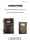
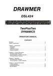
Operating Instructions
GRAPHIC EQUALIZER
E-1231
TOA 1000 series
THE
LIGHTNING
FLASH
WITH
ARROWHEAD WITHIN A TRIANGLE IS
INTENDED TO TELL THE USER THAT
PARTS INSIDE THE PRODUCT ARE A
CAUTION
RISK
TO REDUCE THE RISK OF ELECTRICAL
SHOCK,
DO
NOT
REMOVE
SERVICING
SERVICE PERSONNEL.
TO
ELECTRIC
SHOCK
TO
PERSONS.
COVER.
NO USER SERVICEABLE PARTS INSIDE.
REFER
OF
QUALIFIED
THE EXCLAMATION POINT WITHIN A
TRIANGLE IS INTENDED TO TELL THE
USER THAT IMPORTANT OPERATING
AND SERVICING INSTRUCTIONS ARE
IN
THE
PAPERS
WITH
APPLIANCE.
Please follow the instructions in this manual to obtain the optimum results from this unit.
We also recommend that you keep this manual handy for future reference.
TOA Corporation
THE
Contents
Cautions
2
General Description
3
Features
3
Front Panel
4
Rear Panel
5
Input/Output Connections
6
Installation Precautions
6
Applications
7 • 8
Optional Matching Transformer Mounting
9
Performance Graphs
10
Block Diagram
11
Specifications
12
Accessories
12
Appearance
12
Cautions
1. Do not operate the E-1231 from power mains which exceeds the indicated
mains voltage by more than 10%.
2. Do not expose the E-1231 to corrosive chemicals or liquids such as soft
drinks, salt water, etc.
3. Always refer the E-1231 to qualified technical service personnel.
—2—
General Description
The E-1231 is a single channel, 1/3 octave active graphic equalizer designed to
allow clean, accurate audio equalization for stage, studio, or commercial
applications.
The E-1231 provides 12dB of boost or cut at each of its 28 frequencies, which
are centered at ISO 1/3 octave increments from 31.5Hz to 16kHz.
The E-1231's active bandpass/bandreject filters are designed for minimum
phase shift, and feature smooth slide controls with center detents for easy and
accurate adjustment. (The filters are summed in parallel for reliability, so that
the failure of one filter does not interrupt operation of the others.)
In addition, continuously variable highpass filters are provided on the front
panel. The highpass filter has a slope of 12dB per octave and is variable from
15Hz to 300Hz, while the lowpass filter can set for either a 6dB per octave
slope or a 12dB per octave slope and is variable from 2.5kHz to 30kHz.
An input level control on the E-1231 gives ±12dB of adjustment to allow a wide
variety of input sources. A LED indicator illuminates when either the input or the
output comes within 3dB of clipping. In addition to the usual EQ in/out switch,
an automatic EQ bypass function provides complete equalization bypass in the
event of loss of AC power, and an output muting function suppresses turnon/turn-off transients.
A security cover is included with the E-1231 to guard against accidental
disturbance, or intentional tampering when used in fixed installations.
The E-1231 can be mounted in a standard 19" rack and occupies 3-1/2" of
vertical space.
Features
1. 28 filters on ISO 1/3 octave center frequencies from 31.5Hz to 16kHz.
8. Variable input level control to accept variety of input sources.
2. 12dB boost or cut at each center frequency, continuously variable.
9. Automatic EQ bypass circuitry.
3. High quality, low phase-shift active filters.
10. A security cover is included.
11. Filter In/Out switch
4. Precision calibrated, noiseless slide controls with center detent.
12. Lowpass filter can
6dB/oct or 12dB/oct.
5. Equalizer In/Out switch.
13. Optional input/output transformers that
convert electronically balanced input/output to transformer balanced input/output.
6. Continuously variable highpass and lowpass filters.
7. LED peak indicator to detect clipping at
input or output levels.
—3—
be
set
for
either
Front Panel
Lowpass Filter Slope Selection Switch
This switch sets the lowpass filter's per octave attenuation for either 6dB or 12dB.
Peak Indicator LED
The peak indicator LED lights when either the input or the output level reaches 3 dB below clipping.
Input Level Control
This control adjusts the input gain by ±12dB to allow the use of a wide range of input sources. To
insure the best S/N ratio possible, adjust this control so that the peak LED flashes only occasionally.
Lowpass Filter Control
This is a shelving-type filter that provides a 12dB or 6dB per octave roll off above 2.5kHz and up to
30kHz. Its main purpose is to stop high frequency noise, oscillation, and certain types of RF
interference from damaging tweeters. It is also useful in reducing excessive background noise, such
as that produced by old phonograph records.
Equalizer Sliders
These sliders are adjusted to tune or equalized the overall frequency response of a sound system.
Equalizer Indicator LED
The indicator LED turns on whenever the equalizer IN/OUT switch is "in".
Equalizer IN/OUT Switch
Equalizer switch puts the input signals either in circuit or out of circuit of the equalizer. The "out"
position provides flat audio response no matter what the positions of the equalizer sliders and the
filter (LPF/HPF) control.
Security Cover Mounting Hole
This hole is used to mount the supplied security cover with two screws to avoid accidental changes
in set position of control knobs and switches.
Power Switch
Pushbutton alternately switches the AC power on and off.
Power Indicator LED
The green LED lights when the power switch is "on".
Highpass Filter Control
This shelving-type filter provides an 12dB per octave rolloff between 300Hz and 15Hz. It is especially
useful for reducing stage or turntable rumble, AC hum, wind noise, and other subsonic components
that waste amplifier power and tax speakers.
Filter Indicator LED
The filter indicator LED lights when the filter switch is "in".
Filter IN/OUT Switch
Pressing this switch while equalizer indicator lights provides the frequency response set for by the
lowpass- and highpass-filter control. Press the switch again to disable the lowpass- and highpassfilter control.
—4—
Rear Panel
AC Fuse Holder
When replacing, be sure to use the fuse of specified rating and type to avoid the possibility of fire.
Fuse rating
220-240V version 250V T80mA
120V version 250V 0.2A
AC Power Cord
Ground Screw Terminal
Hum can result from a ground loop to be formed when the E-1231 is connected to other equipment.
In such cases, cut the loop by removing a short piece, which should usually be mounted to the
terminal.
Output Screw Terminal
The output terminal is balanced and 600 ohms in output impedance. Place the supplied short piece
between E and C to convert to unbalanced type.
Input Screw Terminal
The input terminal is balanced and 10k ohms in input impedance. Place the supplied short piece
between E and C to convert to unbalanced type.
—5—
Input/Output Connections
Input terminal from mixer, etc.
E-1231
Input terminal from mixer, etc.
E-1231
Power Amplifier
Speaker System
Installation Precautions
Ground Loops
In any audio system, there are numerous ways by which ground loops can be created.
For example, they may occur when the E-1231 is mounted in a rack cabinet, or
through AC ground when the E-1231 connected with preamps, mixers, etc. These
ground loops may cause hum and noise if care is not taken during connection. An
increase in noise from ground loops may be minimized by breaking the ground loop.
Generally, the chassis ground of the signal line should be broken as shown below.
When hum is generated from a ground loop, detach a short piece from the ground
screw terminal.
—6—
Applications
Feedback Prevention
levels at 500Hz by 3dB to 5dB with the E-1231. If the
overall gain is again gradually increased, feedback will
occur next at about 125Hz. It may be stopped by
attenuating the levels 2dB to 3dB at that frequency. In
this procedure, sufficient gain in the sound system is
obtained before feedback.
Sound Pressure Level
When the overall gain of a sound system is increased,
feedback will occur at frequencies where the system
response has peaks. Suppose the system has an
uneven frequency response like that shown in the
following diagram. The frequency at which feedback
will occur when gain is increased is about 500Hz. In
this case, feedback may be prevented by attenuating
Frequency
Room Equalization
sound clarity.
For example, suppose that there is a room frequency
response as shown below.
The equalizer sliders are set as shown below.
The overall response after equalization
will then be as follows.
Sound Pressure Level
In a sound reinfocement system for a room, the clarity
of sound can be adversely affected by the room
frequency response including standing waves (room
resonances), reflections of sound, and relations
between direct and indirect sound.
The E-1231 is an effective tool to equalize the room
frequency response to a flat response and improve
Frequency
The equalizer sliders are set as shown below.
The overall response after equalization will then be as follows.
Frequency response
of equalizer
Sound Pressure Level
Before equalization
Frequency
—7—
Frequency response
after equalization
Applications
Equalization for music
The Graphic Equalizer is designed not only for use in preventing feedback and
equalizing uneven room frequency response to be flat, but also for equalizing
frequency response to your tastes and producing favorable sound for you. Fig.1 shows
each frequency band and its corresponding auditory feeling. Fig.2 and Table 1 show
the relation between each musical instrument and its frequency band. They can be of
great help in the equalizer operation. (They are referenced from a book entitled
"Practical Guide for concert")
EQUALIZATION CHART
These sounds
are felt more
than
really
heard.
They
give a sense
of power.
Too
much
produces
a
muddy sound.
The rhythm section
appears
here. Either a fat
or thin sound
can be heard by
mis-EQ here. Too
much
becomes
boomy. Bass guitar-Snare-Toms.
INSTRUMENT CHART
Probably the most important of all. Most all
instruments
contain
harmonics here. 300 Hz
boosting can cause horn
like sounds. 1 k to 2 k
sounds tinny. Too much
here sounds like the telephone.
Upper vocal region.
Too much here will
cause great fatigue,
and loose speech intelligence. Reducing
3 k can bring vocals
on top.
Presence
range.
Great achievement
in overall level can
be had here. Too
little causes a "far
away" sound.
Sibilance
levels can be
controlled
here. Bright,
clean definition.
Fig.1
INSTRUMENT EQUALIZATION CHART
Acoustic guitar
Table 1
Bass strings resonate between 70 to 120Hz, body around 300Hz.
Avoid boosting these to stop feedback. 3kHz and 5kHz gives
great "clarity".
Electric guitar
Resonances differ-depending on type. Good full sounds around
300 to 500Hz. Clarity at 3kHz.
Bass guitar
Extreme lows are at 60 to 90Hz. "Pick" or "pluck" sounds are
around 800 to 1200Hz. Upper harmonics clarified about 3kHz.
Human voice
Good fullness at 150Hz. Watch for "boominess" around 250Hz.
Mid-range 10kHz.
Piano (Acoustic)
Bass strings responate around 100Hz. Watch for subharmonics at
30 to 50Hz.
Piano (Electric)
Good mid-clarity at 3kHz to 5kHz thins out rapidly in high end. Be
careful around 1.5kHz to 2.5kHz to avoid the "bar room sound".
Organ
Usually dies under 200Hz. Has great mid-sounds around 1200 to
2000Hz. Top end cuts off at 6kHz.
Violin
Richfullness at 400Hz. Natural mids around 1500 to 2500Hz. Avoid
"scratch" sounds at 8kHz.
Fig.2
Brass instruments
Watch for "hot" mids around 2kHz. Low end boost around 400Hz.
Top end clarity at 6kHz.
Bass drum
Great low "kick" at 40Hz. The mids at 2kHz gives the familiar
"punch".
Snare drum
Good fullness at 100Hz. The "crack" is boosted at 2kHz. Real
easy. The snares extend to above 4kHz.
Tom Tom
The main fullness is around 200Hz. The mid punch extends to
4kHz.
Floor Tom
Same as tom, but extends down to 80Hz.
Hi Hat
Watch for the "gong" sound around 300Hz. Good "shimmer"
sounds are around 8kHz to 10kHz.
Cymbal overhead
About the same as hi-hat only has more low end around 150Hz.
Talk Box
Depending on the guitar sound driving it and the resonance of
each player's mouth, should have great "bite" around 1200Hz and
dies above 6kHz.
—8—
Optional Matching Transformer Mounting
[CAUTION]
THESE SERVICING INSTRUCTIONS ARE FOR USE BY QUALIFIED PERSONNEL ONLY.
TO AVOID ELECTRIC SHOCK DO NOT PERFORM ANY SERVICING OTHER THAN
THAT CONTAINED IN THE OPERATING INSTRUCTIONS UNLESS YOU ARE
QUALIFIED TO DO SO. REFER ALL SERVICING TO QUALIFIED SERVICE PERSONNEL.
The E-1231's input and output are electronically balanced. These can be converted to
transformer balanced input and output using the optional matching transformer LT-101
(input) and LT-102 (output).
1. Set the power switch to OFF and unplug the AC cord form a wall outlet.
2. Remove the case by loosening six side panel screws (three each on each side)
and two rear panel screws.
3. Install sleeves (supplied with the transformer) by tightening screws from the other
side of a chassis, and mount the transformer to the sleeves using screws. See Fig.
1.The input transformer must be located on the left and the output transformer on
the right.
connector from CN-104, reconnect
4. When mounting the input transformer, detach
connector at the transformer side, and then connect
the detached connector to
connector from the transformer to CN104.
connector from CN-103,
When mounting the output transformer, detach
connector at the transformer side, and then
reconnect the detached connector to
connector from the transformer to CN103.
connect
See Fig.1.
Fig.1
5.
Fit the case in place.
Transformer Specifications
Model
Frequency response
Constant loss
Distortion
LT-101
LT-102
30Hz ~ 20kHz
(at ±0.15dB)
30Hz ~ 20kHz
(at ±0.15dB)
Within 1.5dB(at 1kHz)
Within 1.5dB(at 1kHz)
Less than 0.2%(50Hz/5dB)
Less than 0.2%(50Hz/5dB)
0dB = 0.775V RMS
Specifications are subject to change without notice.
—9—
Performance Graphs
Frequency Response
(Each slider is set at a max or min position)
Frequency Response (ex. 800Hz slider)
Frequency Response (ex. 630Hz, 800Hz, 1kHz slider)
High pass Filter
Low pass Filter
— 10 —
Block Diagram
— 11 —
Specifications
Frequency Response
±1dB, 20Hz to 20kHz
Total Harmonic Distortion
Less than 0.01% at 1 kHz, all sliders at 0 position,
rated output
Equalization Center Frequencies
31.5Hz to 16kHz
31.5Hz, 40Hz, 50Hz, 63Hz, 80Hz, 100Hz, 125Hz,
160Hz, 200Hz, 250Hz, 315Hz, 400Hz, 500Hz, 630Hz,
4kHz, 5kHz, 6.3kHz, 8kHz, 10kHz, 12.5kHz, 16kHz
Rated Input Level
+ 4dB (INPUT LEVEL CONTROL set for 0 position)
Rated Output Level
+ 4dB with 600-ohm load
Maximum Input Level
+ 20dB at 1kHz
Maximum Output Level
+ 20dB with 600-ohm load
Input Impedance
10k ohms
Output Impedance
600 ohms
Hum and Noise
—94dB (EQ in, all sliders at 0 position, 20~20kHz
BPF)
Specifications are subject to change without notice.
Indicators
A red LED for output and input clipping, A green
LED for equalizer IN, A green LED for power ON, A
green LED for filter IN
Controls
Equalizer Sliders
±12dB
Input Level Control
±12dB
Highpass Filter
12dB per octave
Adjustable Cutoff Frequency:15Hz to 300Hz
Lowpass Filter
12dB per octave/6dB per octave
Adjustable Cutoff Frequency:2.5kHz to 30kHz
AC Line Voltage
AC mains, 50Hz/60Hz
Power Consumption
11 watts
Finish
Black
Dimensions
(W X H x D)483 x 88 x 317mm(19.0" x 3.5" x 12.5" )
Weight
4.5kg (9.9lbs.)
Note:0 dB is referenced to 0.775 volts RMS.
Accessories
Security cover
Screw for security cover
Short piece
1
2
2
1
1
1
Fuse
Warranty card (for USA and Canada)
Operating instructions
Appearance
mm(inch)
TOA Corporation
KOBE, JAPAN
— 12 —
Printed Japan
133-12-037-2A