1
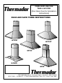
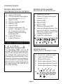
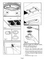
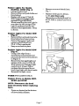
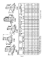
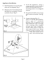
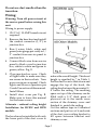
CARE AND USE FOR
WALL HOODS
(Turn Book Over for Installation
Instructions)
READ AND SAVE THESE INSTRUCTIONS
HTSW
HCSW
HDW
HGSW
HSW
5551 McFadden Avenue, Huntington Beach, CA 92649 • 800/735-4328
ECO 71589 • 35-05-017F • © BSH Home Appliances Corp. 1997 • Litho in Italy 10/01
IMPORTANT SAFETY INSTRUCTIONS
WARNING
TO REDUCE THE RISK OF FIRE,
ELECTRIC SHOCK, OR INJURY
TO PERSONS, OBSERVE THE
FOLLOWING:
3. Clean ventilating fans frequently.
Grease should not be allowed to accumulate on fan or filter.
4. Use proper pan size. Always use
cookware appropriate for the size
of the surface element.
CAUTION
FOR GENERAL VENTILATING
USE ONLY. DO NOT USE TO
EXHAUST HAZARDOUS OR
EXPLOSIVE MATERIALS OR
VAPOR.
1. Use this unit only in the manner
intended by the manufacturer. If you
have questions, contact the
manufacturer (800/735-4328).
2. Before servicing or cleaning the unit,
switch power off at service panel and
lock service panel. This will prevent
power from being switched on
accidentally. When the service panel
cannot be locked, securely fasten a
prominent warning device, such as a
tag to the service panel.
WARNING
TO REDUCE THE RISK OF A
RANGE TOP GREASE FIRE.
1. Never leave surface units unattended
at high settings. Boil-overs cause
smoking and greasy spill-overs that
may ignite. Heat oils slowly on low
or medium settings.
2. Always turn hood ON when cooking
on high heat or when flambéing
foods.
WARNING
TO REDUCE THE RISK OF INJURY
TO PERSONS, IN THE EVENT OF A
RANGE TOP GREASE FIRE,
OBSERVE THE FOLLOWING:
a) SMOTHER FLAMES with a closefitting lid, cookie sheet, or other
metal tray, then turn off the gas
burner or the electric element. BE
CAREFUL TO PREVENT
BURNS. If the flames do not go out
immediately, EVACUATE AND
CALL
THE
FIRE
DEPARTMENT.
b) NEVER PICK UP A FLAMING
PAN, you may be burned.
c) DO NOT USE WATER, including
wet dish cloths or towels - a violent
steam explosion may result.
d) Use an extinguisher ONLY if:
1) You know you have a class ABC
extinguisher, and you already
know how to operate it.
2) The fire is small and contained
in the area where it started.
3) The fire department is being
called.
4) You can fight the fire with your
back to an exit.
Page 2
LES INSTRUCTIONS DE SÉCURITÉ IMPORTANTES
AVERTISSEMENT
POUR RÉDUIRE LE RISQUE
D’INCENDIE,
DE
CHOC
ÉLECTRIQUE, OU DE LA
BLESSURE AUX PERSONNES,
OBSERVER LE SUIVANT:
ATTENTION
SEULEMENT POUR
L’UTILISATION D’AÉRATION.
NE PAS L’UTILISER POUR
ÉPUISER LA VAPEUR OU LES
MATIÈRES EXPLOSIVES OU
DANGEREUSES.
1. Utiliser cet appareil seulement dans la
manière destinée par le fabricant. Si
vous avez des questions, contacter le
fabricant (800/735-4328).
2. Avant l’entretien ou le nettoyage de
l’appareil, couper le courant au tableau
de service, et fermer à clef le tableau
de ser vice pour empêcher
l’alimentation d’être allumée par
hasard.
AVERTISSEMENT
POUR RÉDUIRE LE RISQUE D’UN
FEU DE GRAISSE DU SOMMET DE
LA CUISINIÈRE:
1. Garder le ventilateur, les filtres et les
surfaces chargées de la graisse
propres.
2. Toujours mettre le capot EN
MARCHE en cuisinant à la haute
chaleur.
3. Utiliser les hauts positionnements du
cuisinière sur la cuisinière seulement
quand c’est nécessaire. Chauffer l’huile
lentement sur un positionnement bas
à moyen.
4. Ne pas laisser la cuisinière sans
surveillance pendant la cuisson.
5. Utiliser toujours les batteries de
cuisine et les ustensiles appropriés
pour le type et la quantité de la
nourriture ayant préparée.
AVERTISSEMENT
POUR RÉDUIRE LE RISQUE DE
BLESSURE AUX PERSONNES
DANS L’ÉVÉNEMENT D’UN FEU
DE GRAISSE DU SOMMET DE LA
CUISINIÈRE, OBSERVER LES
SUIVANTS:
a) ÉTOUFFER LES FLAMMES avec un
couvercle ajusté, une tôle du biscuit
ou un plateau métallique, puis fermer
le bec.
SOYEZ CERTAIN
D’EMPÊCHER LES BRÛLURES. Si les
flammes ne s’éteindront pas
immédiatement, ÉVACUER ET
APPELER LE SERVICE DES
INCENDIES.
b) NE JAMAIS RAMASSER UNE
CASSEROLE EN FLAMMES - Vous
pouvez être brûlé.
c) NE PAS UTILISER DE L’EAU, y
compris les torchons mouillés ou les
serviettes - une explosion violente
résultera.
d) Utiliser un extincteur SEULEMENT
si:
Page 3
1) Vous savez que vous avez un
extincteur de Classe ABC et vous.
savez déjà comment le faire
fonctionner.
2) Le feu est petit et est contenu dans
la région où il a commencé.
3) Le service des incendies est appelé.
4) Vous pouvez combattre le feu avec
votre dos à une sortie.
CONTROL PANELS
MODELS: HDW, HTSW
ELECTRONIC TOUCH CONTROLS
MODELS: HCSW and HSW
ELECTRONIC PUSH BUTTONS
A. Motor OFF button
B. Motor ON button and speed
selector 1, 2, 3, 1.....
C. Speed 1 LED
D. Speed 2 LED
E. Speed 3 LED
F. Intensive 4th speed LED
G. Intensive 4th speed button - this
speed will run for 10 minutes,
and then return to previous
setting, including OFF.
H. Light ON, OFF button
A. Motor OFF button
B. ON button and motor speed
selection button 1, 2, 3, 1,....
C. Speed 3 LED
D. Intensive 4th Speed LED
E. Speed 1 LED
F. Speed 2 LED
G. Intensive 4th speed ON
switch - this speed will run
for 10 minutes, and then
return to previous setting,
including OFF.
H. Light OFF button
I. Light ON button
Grease Filter Saturation LED
The flashing LED marked D
reminds you when the grease filter
needs to be cleaned after 40 hours
use. Follow the instructions for
cleaning filters in this booklet. Once
the grease filters have been cleaned,
reset reminder by pressing button
A for about 3 seconds until you hear
the signal (beep); the LED D will
now stop flashing.
H
B C DE F G
A
MODELS: HGSW
MECHANICAL PUSH BUTTONS
A.
B.
C.
D.
E.
F.
Hood "ON" indicator light
Light ON-OFF button
Motor OFF button
Motor speed button 1 (low)
Motor speed button 2 (med)
Motor speed button 3 (high)
b.
c.
d.
O
a.
Page 4
e.
1
f.
2
3
OPERATING
INSTRUCTIONS - HOOD
The blower should be turned on for
about 5 minutes before cooking in order
to establish air currents upward through
the hood. Thus when heat, smoke,
moisture, grease and cooking odors are
produced, they will be carried outside
instead of drifting into other rooms.
Use the low speeds for normal use and
the higher speeds for strong odors or
fumes.
Drafts across the range or cooktop will
reduce the effectiveness of the hood.
Such drafts should be prevented when
possible.
CLEANING INSTRUCTIONS
Be sure lights are cool before cleaning
the hood.
To Clean Filter/s
•
It is recommended that the filters
be washed at least once a month;
they can be washed by hand or in
the dishwasher.
•
Drain water through edge holes and
let each filter dry thoroughly before
replacing it.
To Clean Hood Surface
•
For general care, wipe the outside
of the stainless steel, white, black or
glass hood with sudsy water or
household cleaners such as
Fantastic® or Formula 409®, rinse
well and dry with clean soft cloth to
avoid water marks.
•
Wipe and dry brushed stainless steel
in the same direction as the grain.
•
Do not use abrasive products.
•
To remove finger prints and give
added shine use spray cleaners such
as Stainless Steel Magic® and
Shimmer®
FILTERS
The metal grease filters will last forever.
They are made of anodized aluminum
To Remove The Metal Grease
Filter/s
•
Disconnect
electricity.
the
hood
from
for Models HSW, HCSW, HGSW
•
Push clips towards the center and
pull the filters downward. Fig. 1.
for Models HDW, HTSW
• Push each handle towards the back
and pull downwards Fig. 2.
To Replace The Metal Grease
Filter/s
• Reverse procedure.
LIGHTS
NOTE: Disconnect the hood from
electricity and be sure the lights are
cool. If new lights do not operate,
check fuses (see page 7 Fuses) and be
sure lights are inserted correctly before
calling service.
Page 5
Replace Lights For Models HDW,
HGSW, HCSW36/42 (Fig. 3)
• Unscrew the light cover.
• Remove the damaged light and
replace with a new 12 Volt, 20 Watt
(maximum) halogen light made for a
G-4 base. Follow package directions
and do not touch new light with bare
hands.
• Reinstall the light cover.
Page 6
Fig. 7
Page 7
THERMADOR HOOD WARRANTY
Length of Warranty
FULL ONE YEAR WARRANTY
Covers one year from date of installation, or date of occupancy on a new, or
previously unoccupied dwelling. Save your dated receipt or other evidence of
installation/ occupancy date.
Thermador Will Pay For:
All repair labor and replacement parts found to be defective due to materials and
workmanship.
Service must be provided by a Factory Authorized Service Agency, during normal working hours. For a Service Agency nearest you, please call 800/735-4328.
Thermador Will Not Pay For:
1.
2.
Service by an unauthorized agency. Damage or repairs due to service by an
unauthorized agency or the use of unauthorized parts.
Service visits to:
• Teach you how to use the appliance.
• Correct the installation. You are responsible for providing
electrical wiring and other connecting facilities.
• Reset circuit breakers or replace home fuses.
3.
Damage caused from accident, alteration, misuse, abuse, improper installation or installation not in accordance with local electrical codes or plumbing
codes, or improper storage of the appliance.
4.
Repairs due to other than normal home use.
This warranty applies to appliances used in residential applications; it does not cover their
use in commercial installations.
The warranty is for products purchased and retained in the 50 states of the U. S. A., the
District of Columbia and Canada. Should the appliance be sold by the original purchaser
during the warranty period, the new owner continues to be protected until the expiration
date of the original purchaser's warranty period.
This warranty gives you specific legal rights. You may also have other rights which vary
from state to state.
We reserve the right to change specifications or design without notice. Some models are
certified for use in Canada. Thermador is not responsible for products which are transported from the U.S. for use in Canada. Check with your local Canadian distributor or
dealer.
Page 8
INSTALLATION INSTRUCTIONS
WALL HOOD SERIES:
HDW, HSW, HCSW, HGSW, HTSW
FOR RESIDENTIAL USE ONLY
NOT TO BE INSTALLED OVER GAS GRILLS
PLEASE READ ENTIRE INSTRUCTIONS BEFORE PROCEEDING.
INSTALLATION MUST COMPLY WITH ALL LOCAL CODES.
IMPORTANT: Save these Instructions for the Local Electrical Inspector’s use.
INSTALLER: Please leave these Instructions with this unit for the owner.
OWNER: Please retain these instructions for future reference.
Safety Warning: Turn off power circuit at the service entrance and
lock-out panel, before wiring this appliance.
Requirement: 120 V AC, 60 Hz. 15 Amp branch circuit (Appliance Rating see Table 1)
IMPORTANT SAFETY INSTRUCTIONS
WARNING - TO REDUCE THE RISK
OF FIRE, ELECTRIC SHOCK, OR
INJURY
TO
PERSONS,
OBSERVE THE FOLLOWING:
CAUTION:
FOR GENERAL
VENTILATING USE ONLY. DO
NOT USE TO EXHAUST
HAZARDOUS OR EXPLO–SIVE
MATERIALS OR VAPORS.
A. Use this unit only in the manner
intended by the manufacturer. If
you have questions, contact the
manufacturer.
B. Before servicing or cleaning the
unit, switch power off at service
panel and lock service panel
disconnecting means to prevent
power from being switched on
accidentally. When the service
disconnecting means cannot be
locked, attach a tag to the service
panel to indicate power has been
switched off for maintenance.
C. Installation Work and Electrical
Wiring Must Be Done By Qualified
Person(s) In Accordance With All
Applicable Codes & Standards,
Including Fire-rated Construction.
D. Sufficient air is needed for proper
combustion and exhausting of
gases through the flue (chimney)
of fuel burning equipment to
prevent back- drafting. Follow the
heating equipment manufacturers
guideline and safety standards
such as those published by the
National Fire Protection Association (NFPA), the American
Society for Heating, Refrigeration
and Air Conditioning Engineers
(ASHRAE), and the local code
authorities.
READ AND SAVE THESE INSTRUCTIONS
L933C Ed. 05/98
Page 1
E. Due to size and weight of this unit
two installers are recommended.
F. When cutting or drilling into wall
or ceiling, do not damage electrical
wiring and other hidden utilities.
G. Ducted fans must always be
vented to the outdoors. Do not
vent to the attic or crawl space.
H. WARNING - TO REDUCE THE
RISK OF FIRE, USE ONLY
METAL DUCT WORK.
I. Install this hood in accordance with
all requirements specified.
LES INSTRUCTIONS DE SÉCURITÉ IMPORTANTES
AVERTISSEMENT - POUR RÉDUIRE
LE RISQUE D’INCENDIE, DE CHOC
ÉLECTRIQUE, OU DE LA BLESSURE
AUX PERSONNES, OBSERVER LE
SUIVANT:
ATTENTION: SEULEMENT POUR
L’UTILISATION D’AÉRATION. NE
PAS L’UTILISER POUR ÉPUISER LA
VAPEUR OU LES MATIÈRES
EXPLOSIVES OU DANGEREUSES.
A. Utiliser cet appareil seulement dans
la manière destinée par le fabricant.
Si vous avez des questions,
contacter le fabricant.
B. Avant l’entretien ou le nettoyage
de l’appareil, couper le courant au
tableau de service, et fermer à clef
la moyenne de débrayage de service pour empêcher l’alimentation
d’être allumée par hasard. Quand
la moyenne de débrayage de service ne peut pas être fermée à clef,
attacher une étiquette au tableau
de service pour indiquer que
l'alimentation a été coupée pour
l'entretien.
C. Le Travail d’Installation et de
Câblage Électrique Doit Être
Fait Par les Personne(s)
Qualifiées Conformément à
Tous les Codes & Nor mes
Applicables, y Compris la Construction Calculée à Feu.
D. L’écoulement comburant pour le
fonctionnement sûr du matériel
de la combustion du combustible
peut être affecté par le
fonctionnement de cet appareil.
Suivre la directive des fabricants
du matériel chauffant et les normes
de sécurité tel que ceux publiées
par l’Association du Protection de
Feu National (NFPA), et la Société
Américaine pour les Ingénieurs de
Chauffage, de Réfrigération et de
Climatisa- tion (ASHRAE), et les
autorités des codes locales.
E. Par suite de la dimension et le
poids de cet appareil, deux
installateurs sont recommandés.
F. En coupant ou en forant dans un
mur ou dans un plafond, ne pas
endommager le câblage électrique
et des autres utilités cachées.
G. Les ventilateurs canalisés doivent
être toujours déchargés à
l’extérieur et vers le haut. Ne pas
décharger au grenier ou au vide
sanitaire.
H. Pour réduire le risque d’incendie,
utiliser seulement le travail du
conduit métallique.
I.
Page 2
Installer ce capot conformé- ment
aux toutes exigences spécifiées par
le fabricant de votre cooktop/
cuisinière.
Page 3
HDW
W
60
64
73
5
62
68
37
42
57
68
88
HDW36
HDW42
HDW48
HCSW36
HCSW42
HCSW48
HSW30
HSW36
HTSW36
HTSW42
HGSW36
33"
33"
33"
33"
33"
33"
33"
33"
33"
33"
33"
30-3/4"
30-3/4"
30-3/4"
25-5/8"
25-5/8"
29-3/4"
29-3/4"
25-5/8"
Min.
54"
45-7/8"
45-7/8"
42-1/2"
42-1/2"
47-1/4"
47-1/4"
47-1/4"
49-1/4"
49-1/4"
49-1/4"
Max.
HTSW
HEIGHT
H
W
27-1/4"
27-1/4"
27-1/4"
*
D
H
H
W
HCSW
T
36"
36"
42"
30"
36"
36"
42"
48"
36"
42"
48"
19-5/8"
18-7/8"
18-7/8"
20-1/4"
20-1/4"
21-5/8"
21-5/8"
21-5/8"
23-1/4"
23-1/4"
23-1/4"
WIDTH DEPTH
W
D
D
* Height if Upper Telescope Piece is Left Off.
** Distance from wall to centerline of transition
pounds
CARTON
WEIGHT
MODEL #
TABLE 1
T
T
W
18-1/2"
19-5/8"
19-5/8"
14-3/4"
14-3/4"
14-3/4"
14-3/4"
14-3/4"
15-7/8"
15-7/8"
15-7/8"
6-3/8"
3-1/4"
3-1/4"
3-3/4"
3-3/4"
3-3/4"
3-3/4"
3-3/4"
4-7/8"
4-7/8"
4-7/8"
6"
6"
6"
6"
6"
6"
6"
6"
8"
8"
8"
400
400
400
400
400
400
400
400
770
770
770
D
T
W
HSW
2
2
2
2
2
2
2
2
2
4
4
40W
40W
40W
18W
18W
40W
40W
40W
40W
80W
80W
220W
220W
220W
220W
220W
220W
220W
220W
440W
440W
440W
2.16A
2.16A
2.16A
2.A
2.A
2.16A
2.16A
2.16A
4.A
4.33A
4.33A
D
H
# OF
ELECTRICAL
LIGHTS Lights Motor
Total
T
Voltage 120V AC 60Hz
166
312
312
310
310
310
310
427
320
320
427
sq inch
FILTER
SIZE
HGSW
TRANSITIION DUCT CFM
T
A** SIZE
D
H
H
Parts Included with your
Hood
•
•
•
•
•
•
•
•
•
•
•
•
•
Parts Not Included with
your Hood
Hood Canopy Assembly with
Ventilator and Light Bulbs
Installed
Care & Use /Installation
Instructions
Registration Card.
Filters, 1, 2, 3 or 4 depending on
model and size
Plastic Transition with Back draft
dampers installed
Screws and Drywall Anchors
2 Mounting Hooks
Mounting Temple
2 Piece Duct Cover
Rubber Tape (only for HSW and
HCSW model)
6" or 8" Starting Collar
Contents Sheet
2 Rubber Gaskets
•
Metal Transition if required
HGTR6 for HGSW model
HSTR6 for all other 400 CFM
hoods
HDTR8 for HDW models
•
Duct Tape
•
1/2" Conduit
•
Wire Nuts
•
Plywood Wall Mounting Block
CONSIDERATIONS BEFORE INSTALLING HOOD
break. The break should be as
close as possible to where the
ducting enters the heated portion
of the house.
1. For the most efficient air flow
exhaust, use a straight run or as
few elbows as possible.
CAUTION: Vent unit to outside
of building, only.
2. Use flex ducting only to connect
rigid duct directly to transitions.
3. COLD WEATHER installations
should have an additional
backdraft damper installed to
minimize backward cold air flow
and a nonmetallic thermal break
to minimize conduction of outside
temperatures as part of the
ductwork. The damper should be
on the cold air side of the thermal
4. Hood installation height above
cooktop is the users preference.
The lower the hood above the
cooktop, the more efficient the
capturing of cooking odors,
grease and smoke. Thermador
recommends the hood be installed
30-36" above the countertop. The
lower height may be inconvenient
for tall people and large cooking
vessels. Check your ceiling height
and the hood height maximum
before you select your hood.
Page 4
Preparation of mounting
surface (Drywall)
1. Select a mounting height
comfortable for the user and
mark on wall behind cooktop.
2. Mark center line of cooktop and
draw vertical line from bottom
of hood to the ceiling.
3. Tape template, matching centerline and hood bottom as shown
in Fig. A.
4. Mark centers of the 6 fastener
locations through template on
wall then remove template.
5. Mark wall with horizontal line
1" above highest and 1" below
lowest fastener location.
6. Find studs behind drywall by
tapping wall or using a stud finder.
Mark the center of the studs with a
vertical line to the right and left of
the marked fastener location.
Note: Each 2 x 6 must span at
least 2 studs side to
side.
7. Cutout
drywall
along marked lines.
Install each 2 x 6
between studs firmly flush with stud
front. Make sure all
mounting screws
will anchor to added
lumber. Replace
drywall and refinish.
8. Remark center line
and hood bottom on
same location as
before and tape
template on wall as
in step 3 above.
9. Mount 2 mounting hooks with
wood screws (supplied in
mounting hardware kit) on
locations marked on template,
then remove template.
10. Install duct cover ceiling bracket
to wall flush to ceiling with
drywall anchors supplied. Fig.
B.
Page 5
Appliance Installation:
A. Install transition on top of hood if
removed for shipping. Fig. C
B. Hang hood on 2 mounting hooks
through the rectangular cutouts
on back of hood. Fig. D
C. Level the appliance, using a
carpenters level across bottom of
hood with leveling screws in
mounting hooks or rectangular
cutouts.
D. Secure hood with 2 screws on top
and 2 screws on bottom. See Fig.
D.
E. Connect ducting (Fig. C).
Note: for blower serviceability,
leave a gap of 1" minimum
between top of transition and
sheet metal duct and cover gap
with a starting collar wrapped
around duct and transition.
Locate collar screws so they fit
into corner of duct cover. Secure
collar to transition and duct with
three sheet metal screws
each. Seal with duct tape.
Page 6
Do not use duct smaller than the
transition.
Wiring:
Warning: Turn off power circuit at
the service panel before wiring this
unit.
Wiring to power supply
1. 120 V AC, 15 AMP branch circuit
required.
2. Remove the knockout and install
the conduit connector (1/2") in
junction box.
3. Run 3 wires; black, white and
green (wire gauge per code) in 1/
2" conduit from service panel to
junction box.
4. Connect black wire from service
panel to black or red in junction
box, white to white and green to
green-yellow. Fig. E.
5. Close junction box cover. Check
all light bulbs to make sure they
are secure in their sockets. Turn
power on in service panel. Check
lights and blower operation per
Care & Use section of this manual.
Install filters.
6. Install duct cover per Fig. B.
Make sure to leave this manual
for the home owner.
Alternate - reduced ceiling height
Installation for HCSW and HSW
models:
The hood may be installed with only
the lower part of the duct cover to
reduce the overall height. This hood
height is signified by * in Table 1.
For the duct cover to slide down and
engage the top of the hood, the
ceiling bracket must be mounted 1/
4" below the ceiling. The resulting
space on top of the chimney can be
filled with a 1/4” thick piece of
plywood cut to the inside cross
section of the chimney cover and
finished to match the ceiling.
Cut the rubber tape in 4 identical
sections and put two of it each side
of the duct cover ceiling bracket to
fill space between bracket and
chimney cover.
Page 7
Alternate - reduced ceiling height
Installation for HDW and HTSW
and HGSW models:
The hood may be installed with only
the lower part of the duct cover to
reduce the overall height. This hood
height is signified by * in Table 1. For
the duct cover to slide down and
engage the top of the hood, the ceiling
bracket must be mounted 1/4" below
the ceiling. The resulting space on
top of the chimney can be filled with
a 1/4” thick piece of plywood cut to
the inside cross section of the chimney
cover and finished to match the
ceiling.
Copy the two mounting holes on the
sides of the upper cover to the lower
cover.
Rear discharge:
A 90° elbow may be installed
immediately above the hood. For
serviceability, a mounting similar to
the straight up discharge shown in
Fig. C should be used. In Table 1
dimension "T" signifies distance from
hood bottom to top of transition.
Page 8


![一括ダウンロード [PDFファイル/276KB]](http://vs1.manualzilla.com/store/data/006680327_3-705d200a828bb338df8a4d4ae2cbad74-150x150.png)