1
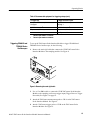
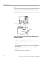
Instruction Manual
80A03
TekConnect Probe Interface Module
071-1298-01
This document applies to firmware version 1.00
and above.
Warning
The servicing instructions are for use by qualified
personnel only. To avoid personal injury, do not
perform any servicing unless you are qualified to
do so. Refer to all safety summaries prior to
performing service.
www.tektronix.com
Copyright © Tektronix, Inc. All rights reserved.
Tektronix products are covered by U.S. and foreign patents, issued and pending. Information in this publication supercedes
that in all previously published material. Specifications and price change privileges reserved.
Tektronix, Inc., P.O. Box 500, Beaverton, OR 97077-0001
TEKTRONIX, TEK, and TekConnect are registered trademarks of Tektronix, Inc.
WARRANTY
Tektronix warrants that the products that it manufactures and sells will be free from defects in materials and
workmanship for a period of one (1) year from the date of shipment. If a product proves defective during this
warranty period, Tektronix, at its option, either will repair the defective product without charge for parts and labor,
or will provide a replacement in exchange for the defective product.
In order to obtain service under this warranty, Customer must notify Tektronix of the defect before the expiration
of the warranty period and make suitable arrangements for the performance of service. Customer shall be
responsible for packaging and shipping the defective product to the service center designated by Tektronix, with
shipping charges prepaid. Tektronix shall pay for the return of the product to Customer if the shipment is to a
location within the country in which the Tektronix service center is located. Customer shall be responsible for
paying all shipping charges, duties, taxes, and any other charges for products returned to any other locations.
This warranty shall not apply to any defect, failure or damage caused by improper use or improper or inadequate
maintenance and care. Tektronix shall not be obligated to furnish service under this warranty a) to repair damage
resulting from attempts by personnel other than Tektronix representatives to install, repair or service the product;
b) to repair damage resulting from improper use or connection to incompatible equipment; c) to repair any
damage or malfunction caused by the use of non-Tektronix supplies; or d) to service a product that has been
modified or integrated with other products when the effect of such modification or integration increases the time
or difficulty of servicing the product.
THIS WARRANTY IS GIVEN BY TEKTRONIX IN LIEU OF ANY OTHER WARRANTIES, EXPRESS
OR IMPLIED. TEKTRONIX AND ITS VENDORS DISCLAIM ANY IMPLIED WARRANTIES OF
MERCHANTABILITY OR FITNESS FOR A PARTICULAR PURPOSE. TEKTRONIX’
RESPONSIBILITY TO REPAIR OR REPLACE DEFECTIVE PRODUCTS IS THE SOLE AND
EXCLUSIVE REMEDY PROVIDED TO THE CUSTOMER FOR BREACH OF THIS WARRANTY.
TEKTRONIX AND ITS VENDORS WILL NOT BE LIABLE FOR ANY INDIRECT, SPECIAL,
INCIDENTAL, OR CONSEQUENTIAL DAMAGES IRRESPECTIVE OF WHETHER TEKTRONIX OR
THE VENDOR HAS ADVANCE NOTICE OF THE POSSIBILITY OF SUCH DAMAGES.
Table of Contents
General Safety Summary . . . . . . . . . . . . . . . . . . . . . . . . . . . . . . . . . . .
Service Safety Summary . . . . . . . . . . . . . . . . . . . . . . . . . . . . . . . . . . . .
iii
v
Contacting Tektronix . . . . . . . . . . . . . . . . . . . . . . . . . . . . . . . . . . . . . . . . . . . . .
vi
The TekConnect Interface . . . . . . . . . . . . . . . . . . . . . . . . . . . . . . . . . . . . . . . . .
Standard Accessories . . . . . . . . . . . . . . . . . . . . . . . . . . . . . . . . . . . . . . . . . . . . .
Optional Accessories . . . . . . . . . . . . . . . . . . . . . . . . . . . . . . . . . . . . . . . . . . . . .
Installing the TekConnect Probe Interface Module . . . . . . . . . . . . . . . . . . . . . .
Performing a Functional Check . . . . . . . . . . . . . . . . . . . . . . . . . . . . . . . . . . . . .
Calibrating the TekConnect Probe Interface Module . . . . . . . . . . . . . . . . . . . .
2
3
3
4
9
12
Understanding the Controls . . . . . . . . . . . . . . . . . . . . . . . . . . . . . . . . . . . . . . . .
Triggering the Sampling Oscilloscope . . . . . . . . . . . . . . . . . . . . . . . . . . . . . . . .
Sampling Module Incompatibility . . . . . . . . . . . . . . . . . . . . . . . . . . . . . . . . . . .
13
14
19
Avoiding Damage from Overvoltage . . . . . . . . . . . . . . . . . . . . . . . . . . . . . . . . .
Avoiding Damage from Electrostatic Discharge . . . . . . . . . . . . . . . . . . . . . . . .
21
21
Electrical characteristics . . . . . . . . . . . . . . . . . . . . . . . . . . . . . . . . . . . . . . . . . . .
Environmental characteristics . . . . . . . . . . . . . . . . . . . . . . . . . . . . . . . . . . . . . .
Physical characteristics . . . . . . . . . . . . . . . . . . . . . . . . . . . . . . . . . . . . . . . . . . . .
23
23
24
Inspecting and Cleaning . . . . . . . . . . . . . . . . . . . . . . . . . . . . . . . . . . . . . . . . . . .
Troubleshooting . . . . . . . . . . . . . . . . . . . . . . . . . . . . . . . . . . . . . . . . . . . . . . . . .
Replacing Parts . . . . . . . . . . . . . . . . . . . . . . . . . . . . . . . . . . . . . . . . . . . . . . . . . .
Repackaging for Shipment . . . . . . . . . . . . . . . . . . . . . . . . . . . . . . . . . . . . . . . . .
25
25
26
26
Parts Ordering Information . . . . . . . . . . . . . . . . . . . . . . . . . . . . . . . . . . . . . . . . .
Using the Replaceable Parts List . . . . . . . . . . . . . . . . . . . . . . . . . . . . . . . . . . . .
27
28
Getting Started
Operating Basics
Reference
Specifications
Maintenance
Replaceable Parts
80A03 TekConnect Probe Interface Module Instruction Manual
i
Table of Contents
List of Figures
Figure 1: The 80A03 TekConnect Probe Interface Module . . . . . . . .
Figure 2: TekConnect Probe Interface Module inputs and
outputs . . . . . . . . . . . . . . . . . . . . . . . . . . . . . . . . . . . . . . . . . . . . . . .
Figure 3: Extender cable connection to the sampling
oscilloscope . . . . . . . . . . . . . . . . . . . . . . . . . . . . . . . . . . . . . . . . . . . .
Figure 4: Installing the sampling module into the
TekConnect Probe Interface Module . . . . . . . . . . . . . . . . . . . . . . .
Figure 5: Connecting the sampling module . . . . . . . . . . . . . . . . . . . .
Figure 6: Installing TekConnect probes . . . . . . . . . . . . . . . . . . . . . . .
Figure 7: Equipment setup for functional check . . . . . . . . . . . . . . . .
Figure 8: Removing the semi-rigid cable . . . . . . . . . . . . . . . . . . . . . . .
Figure 9: Setup for triggering the sampling oscilloscope
using the 80A03 TekConnect Probe Interface Module . . . . . . . .
Figure 10: Trigger offset indicator . . . . . . . . . . . . . . . . . . . . . . . . . . . .
Figure 11: Setup for triggering the sampling oscilloscope
and viewing signals using the 80A03 TekConnect Probe
Interface Module . . . . . . . . . . . . . . . . . . . . . . . . . . . . . . . . . . . . . . .
Figure 12: 80A03 replaceable parts . . . . . . . . . . . . . . . . . . . . . . . . . . .
1
4
5
6
7
8
10
15
16
17
18
29
List of Tables
Table 1: 80A03 features and standard accessories . . . . . . . . . . . . . . .
Table 2: Recommended equipment for performing a
functional check . . . . . . . . . . . . . . . . . . . . . . . . . . . . . . . . . . . . . . . .
Table 3: Recommended equipment for triggering setup . . . . . . . . . .
Table 4: Electrical characteristics . . . . . . . . . . . . . . . . . . . . . . . . . . . .
Table 5: Environmental characteristics . . . . . . . . . . . . . . . . . . . . . . . .
Table 6: Physical characteristics . . . . . . . . . . . . . . . . . . . . . . . . . . . . .
ii
3
9
14
23
23
24
80A03 TekConnect Probe Interface Module Instruction Manual
General Safety Summary
Review the following safety precautions to avoid injury and prevent damage to
this product or any products connected to it.
To avoid potential hazards, use this product only as specified.
Only qualified personnel should perform service procedures.
While using this product, you may need to access other parts of the system. Read
the General Safety Summary in other system manuals for warnings and cautions
related to operating the system.
To Avoid Fire or
Personal Injury
Connect and Disconnect Properly. Do not connect or disconnect probes or test
leads while they are connected to a voltage source.
Connect the probe output to the measurement instrument before connecting the
probe to the circuit under test. Disconnect the probe input and the probe ground
from the circuit under test before disconnecting the probe from the measurement
instrument.
Ground the Product. This product is indirectly grounded through the grounding
conductor of the mainframe power cord. To avoid electric shock, the grounding
conductor must be connected to earth ground. Before making connections to the
input or output terminals of the product, ensure that the product is properly
grounded.
Observe All Terminal Ratings. To avoid fire or shock hazard, observe all ratings
and markings on the product. Consult the product manual for further ratings
information before making connections to the product.
The common terminal is at ground potential. Do not connect the common
terminal to elevated voltages.
Connect the ground lead of the probe to earth ground only.
Do Not Operate Without Covers. Do not operate this product with covers or panels
removed.
Avoid Exposed Circuitry. Do not touch exposed connections and components
when power is present.
Do Not Operate With Suspected Failures. If you suspect there is damage to this
product, have it inspected by qualified service personnel.
Do Not Operate in Wet/Damp Conditions.
Do Not Operate in an Explosive Atmosphere.
Keep Product Surfaces Clean and Dry.
80A03 TekConnect Probe Interface Module Instruction Manual
iii
General Safety Summary
Symbols and Terms
Terms in this Manual. These terms may appear in this manual:
WARNING. Warning statements identify conditions or practices that could result
in injury or loss of life.
CAUTION. Caution statements identify conditions or practices that could result in
damage to this product or other property.
Terms on the Product. These terms may appear on the product:
DANGER indicates an injury hazard immediately accessible as you read the
marking.
WARNING indicates an injury hazard not immediately accessible as you read the
marking.
CAUTION indicates a hazard to property including the product.
Symbols on the Product. The following symbols may appear on the product:
CAUTION
Refer to Manual
iv
80A03 TekConnect Probe Interface Module Instruction Manual
Service Safety Summary
Only qualified personnel should perform service procedures. Read this Service
Safety Summary and the General Safety Summary before performing any service
procedures.
Do Not Service Alone. Do not perform internal service or adjustments of this
product unless another person capable of rendering first aid and resuscitation is
present.
Disconnect Power. To avoid electric shock, switch off the instrument power, then
disconnect the power cord from the mains power.
Use Care When Servicing With Power On. Dangerous voltages or currents may
exist in this product. Disconnect power, remove battery (if applicable), and
disconnect test leads before removing protective panels, soldering, or replacing
components.
To avoid electric shock, do not touch exposed connections.
80A03 TekConnect Probe Interface Module Instruction Manual
v
Service Safety Summary
Contacting Tektronix
Phone
1-800-833-9200*
Address
Tektronix, Inc.
Department or name (if known)
14200 SW Karl Braun Drive
P.O. Box 500
Beaverton, OR 97077
USA
Web site
www.tektronix.com
Sales support
1-800-833-9200, select option 1*
Service support
1-800-833-9200, select option 2*
Technical support
Email: [email protected]
1-800-833-9200, select option 3*
6:00 a.m. - 5:00 p.m. Pacific time
*
vi
This phone number is toll free in North America. After office hours, please leave a
voice mail message.
Outside North America, contact a Tektronix sales office or distributor; see the
Tektronix web site for a list of offices.
80A03 TekConnect Probe Interface Module Instruction Manual
Getting Started
The 80A03 TekConnect Probe Interface Module is an adapter that allows you to
use TekConnect probes with CSA8000 and TDS8000 Series sampling oscilloscopes and 80E0X sampling modules. The interface is comprised of an enclosure
that houses a compartment for one 80E0X electrical sampling module and two
TekConnect probe inputs. The interface connects to the sampling oscilloscope
through a permanently attached 1 meter extender cable.
Figure 1: The 80A03 TekConnect Probe Interface Module
The 80A03 TekConnect Probe Interface Module also allows you the flexibility of
using the interface as a general-purpose sampling module extender cable by
simply disconnecting the short semi-rigid cables on the front panel of the
interface and using the sampling module inputs directly.
The TekConnect Probe Interface Module supports probe interface conversion
between CSA8000 and TDS8000 Series sampling oscilloscopes and the
following TekConnect probes.
Supported TekConnect probes
Dynamic Range
P7225
P7240
P7260
P7330
P7350
P7350SMA
As reported on the probe label
P7380
1.5 Vpk-pk (5X), 6 Vpk-pk (25X)1
P7380SMA
1 Vpk-pk (2.5X), 5 Vpk-pk (12.5X)1
1
This differs from the probe label. See the probe label for actual limits.
80A03 TekConnect Probe Interface Module Instruction Manual
1
Getting Started
The following electrical sampling modules are recommended for use with the
TekConnect Probe Interface Module.
Recommended Tektronix
sampling modules
Description
80E011
Single channel, 50 GHz
80E022
Dual channel, 12.5 GHz
80E032
Dual channel, 20 GHz
80E042
Dual Channel, 20 GHz with TDR
80E061
Single channel, 70 GHz
1
Requires 2.4/1.85 mm to 2.92 mm SMA adapter (Tektronix part number 011- 0157- 00,
standard with these sampling modules). Also requires custom cable not available
from Tektronix: use a short high-quality SMA cable or fabricate your own semi-rigid
cable.
2
Recommended for use with 80A03 TekConnect Probe Interface Module.
The 80A03 TekConnect Probe Interface Module does not support the Tektronix
P6209 probe. For this probe, the interface disables the sampling module inputs.
There is also no support for TekProbe Level 2 legacy probes that utilize the
TCA-1MEG, TCA-BNC, and TCA75 adapters.
The TekConnect Interface
Power for the 80A03 TekConnect Probe Interface Module, sampling module, and
TekConnect probes is supplied through the cable that connects the TekConnect
Probe Interface Module to the sampling oscilloscope. The same cable also
provides a data and communications path from the probe contact pins through
the interface to the oscilloscope. Power, signal, offset, and probe characteristic
data transfers through this interface.
When a probe is connected, the TekConnect Probe Interface Module reads
information from the probe, identifies the device, and turns on the appropriate
power supplies.
2
80A03 TekConnect Probe Interface Module Instruction Manual
Getting Started
Standard Accessories
Table 1 lists the 80A03 TekConnect Probe Interface Module features and
standard accessories.
Table 1: 80A03 features and standard accessories
Accessory
Description
Semi-Rigid Cables. Consists of two semi-rigid SMA-to-SMA cables for connecting the electrical
sampling module to the TekConnect Probe Interface Module, Tektronix part number
174-4857-xx.
Statement of
compliance
Statement of compliance. A certificate verifying the product was assembled and verified using
established procedures and work instructions. When applicable, test equipment is traceable to
known standards.
Included with product at initial shipment. This accessory cannot be ordered.
Instruction Manual. Provides instructions for operating and maintaining the 80A03 TekConnect
Probe Interface Module, Tektronix part number 071-1298-xx.
Optional Accessories
No optional accessories are available for the 80A03 TekConnect Probe Interface
Module.
80A03 TekConnect Probe Interface Module Instruction Manual
3
Getting Started
Installing the TekConnect Probe Interface Module
Figure 2 shows the TekConnect Probe Interface Module and locations of the
sampling module and probe inputs. The extender cable on the rear of the
interface connects to the sampling oscilloscope front panel.
Extender cable
Sampling
module
TekConnect
probe input
Semi-rigid
cable
Figure 2: TekConnect Probe Interface Module inputs and outputs
Installing the TekConnect Probe Interface Module consists of the following
steps:
1. Connecting the Interface Module to the Sampling Oscilloscope.
2. Installing the Sampling Module.
3. Installing the Semi-Rigid SMA Connector Cables.
4. Installing the TekConnect Probe.
4
80A03 TekConnect Probe Interface Module Instruction Manual
Getting Started
Connecting the Interface
Module to the Sampling
Oscilloscope
To install the TekConnect Probe Interface Module Extender Cable into the front
panel of the sampling oscilloscope, perform the following tasks:
CAUTION. To prevent damage to the sampling module, never install or remove a
module when the sampling oscilloscope is powered on or when either input
connector is left unprotected. Follow the precautions described in your sampling
module and oscilloscope manuals to avoid damage.
1. Turn off the sampling oscilloscope using the front-panel On/Standby switch.
2. Install the TekConnect Probe Interface Module Extender Cable connector
into any of the small sampling module compartments on the front panel of
the sampling oscilloscope. See Figure 3.
3. Push the module in slowly with firm pressure to seat it.
4. Tighten the hold-down screw to hold the connector in place. To remove the
connector later, loosen the hold-down screw and slide the ejector lever.
NOTE. Installing a large sampling module into a large compartment of the
sampling oscilloscope may disable channels on a small module already
installed. Refer to the documentation for the sampling oscilloscope about
compartment interaction.
CSA/TDS8000
sampling oscilloscope
Hold-down
screw
Figure 3: Extender cable connection to the sampling oscilloscope
NOTE. Do not use any additional extender cables to connect the 80A03
TekConnect Probe Interface Module to the sampling oscilloscope.
80A03 TekConnect Probe Interface Module Instruction Manual
5
Getting Started
Installing the Sampling
Module
To install the sampling module into the front panel of the TekConnect Probe
Interface Module, perform the following tasks:
CAUTION. Sampling modules are inherently vulnerable to static damage. Always
observe static-safe procedures and precautions as outlined in your sampling
module user manual.
1. Verify that the sampling oscilloscope is powered off; if necessary, toggle the
front-panel On/Standby switch.
2. Insert the sampling module into the front-panel compartment of the
TekConnect Probe Interface Module as shown in Figure 4.
3. Push the module in slowly with firm pressure to seat it.
4. Once the module is seated, turn the hold-down screw to tighten the sampling
module in place. See Figure 4.
5. To release the module later, loosen the hold-down screw fully, and then slide
the ejector lever.
Ejector lever
Hold-down screw
Sampling module
Figure 4: Installing the sampling module into the TekConnect Probe Interface
Module
NOTE. To remove the sampling module, first loosen the hold-down screw; then
use the ejector lever on the interface module to eject the sampling module.
6
80A03 TekConnect Probe Interface Module Instruction Manual
Getting Started
Installing the Semi-Rigid
SMA Connector Cables
To provide a signal path between the sampling module and the TekConnect
Probe Interface Module, perform the following tasks:
1. Connect your wrist strap to the antistatic connector on the front of the
sampling oscilloscope.
2. Use the two semi-rigid SMA cables (included with this product) to connect
the TekConnect Probe Interface Module to the sampling module as shown in
Figure 5. To obtain proper alignment and mate the SMA connectors, you
may need to change the bend angle of the center bend. It is recommended
that you do not change the bend angle by more than 1/8 in.
NOTE. Always use a calibrated torque wrench to install adapters, attenuators,
cables, or power sensors in any setup. Torque all connections to 8 ±0.3 inch
pounds. For information on proper installation and torquing techniques, refer to
your sampling module user manual.
Figure 5: Connecting the sampling module
CAUTION. The semi-rigid SMA connector cables used on the 80A03 TekConnect
Probe Interface Module are not compatible with the input connections of
80E01and 80E06 sampling modules.
Do not attempt to force a connection between the semi-rigid connector cables on
the TekConnect Probe Interface Module and these sampling modules. Use the
proper adapter or damage to the sampling module will occur. See page 2 for
additional information.
80A03 TekConnect Probe Interface Module Instruction Manual
7
Getting Started
Installing the TekConnect
Probe
The TekConnect probe features a spring-loaded latch that provides audible and
tactile confirmation that a reliable connection has been made to the TekConnect
Probe Interface Module.
NOTE. It is not necessary to power off the sampling oscilloscope when removing
or installing a TekConnect probe.
To connect a TekConnect probe to the TekConnect Probe Interface Module,
perform the following tasks:
1. Slide the probe into the TekConnect receptacle on the TekConnect Probe
Interface Module. The probe snaps into the TekConnect Probe Interface
Module when fully engaged. See Figure 6.
2. To release the probe from the TekConnect Probe Interface Module, grasp the
compensation box, press the latch button, and pull out on the probe.
Latch button
Figure 6: Installing TekConnect probes
8
80A03 TekConnect Probe Interface Module Instruction Manual
Getting Started
Performing a Functional Check
To verify that the 80A03 TekConnect Probe Interface Module is functioning
properly, perform the following procedure.
Refer to Table 2 for a list of recommended equipment.
Table 2: Recommended equipment for performing a functional check
Item description
Recommended example
Sampling oscilloscope
Tektronix CSA8000 or TDS8000
Sampling module
Tektronix 80E02, 80E03, or 80E04
TekConnect probe
Tektronix P7000 Series
Probe tip adapter
Tektronix P7225, P7240: 015-0678-xx
Tektronix P7260: 067-1456-xx
Tektronix P7330, P7350: 067-0419-00
Semi-rigid SMA cables (2)
Tektronix part number 174-4857-xx
SMA cable
Tektronix part number 174-1427-00
50 Ω termination, SMA-type
Tektronix part number 015-1022-xx
Torque wrench
SMA 5/16, 8 in-lb
To verify the functionality of Channel A, perform the following tasks:
1. Initialize the system:
a. Power on the sampling oscilloscope.
b. Wait for the boot up process to complete.
c. Press the front panel Default Setup button.
2. Connect the signal source:
a. On the sampling oscilloscope, connect the SMA cable to the Internal
Clock Output. See Figure 7 on page 10 for details.
b. Connect the Probe Tip Adapter with 50 Ω termination to the other end of
the SMA cable.
3. Set up the trigger system:
a. In the UI application toolbar, select Internal Clock from the Trig List
menu box.
80A03 TekConnect Probe Interface Module Instruction Manual
9
Getting Started
4. Connect the probe:
a. Attach the P7000 Series probe to the Channel A input of the 80A03
TekConnect Probe Interface Module.
b. Install the probe tip onto the probe tip adapter.
Figure 7: Equipment setup for functional check
5. Set up the channel for test:
a. On the sampling oscilloscope, press the channel button to select the
channel that is connected.
The Channel button lights, the sampling module LED lights, and the
selected channel on the sampling oscilloscope becomes active.
b. Turn the Vertical scale knob and set the sensitivity to display a waveform
similar to the one shown in Figure 7.
c. Turn the Horizontal scale knob to indicate 2 s/div.
10
80A03 TekConnect Probe Interface Module Instruction Manual
Getting Started
6. Verify the channel operation:
a. Verify the LED on the TekConnect Probe Interface Module for the
channel under test is Green.
b. On the sampling oscilloscope verify the probe model, serial number,
scale, dynamic range, impedance, and other information by selecting the
Utilities > System Properties > Probes menu for the channel under test.
NOTE. The sampling oscilloscope displays the first six characters of the
TekConnect probe model and truncates the remaining characters. For
example, the oscilloscope will identify a P7350SMA probe as P7350S.
The impedance value displayed for P7330, P7350, and P7350SMA
probes is for single-ended configuration. The displayed value is one half
the value listed on the probe label.
c. On the sampling oscilloscope, verify that the extender cable length is
listed as 1 meter in the Utilities > System Properties > Sampling
Modules menu.
d. On the sampling oscilloscope, verify that the signal displayed is a square
wave of approximately 1 Vp-p with a 5 s period.
e. Adjust the offset and verify that the display signal moves vertically to
the offset level.
f.
Adjust the vertical scale and verify that the displayed signal height
changes.
To verify functionality of the TekConnect Probe Interface Module Channel B,
perform the following tasks:
1. Connect the probe to Channel B instead of Channel A.
2. Repeat steps 5 through 6 above.
Functional Checks for
Other Equipment
To verify that the oscilloscope, sampling module, or TekConnect probe is
performing properly, run the calibration, compensation, or functional verification
procedure recommended for the individual product. For detailed instructions,
refer to the user manuals that accompanied these products.
80A03 TekConnect Probe Interface Module Instruction Manual
11
Getting Started
Calibrating the TekConnect Probe Interface Module
The 80A03 TekConnect Probe Interface Module requires no internal calibration.
However, after installing any sampling module, you should run a compensation
procedure from the sampling oscilloscope. This ensures that the entire test
system meets warranted accuracy specifications with the TekConnect interface
and probe attached. Refer to your sampling module, probe, and oscilloscope
manuals for specific calibration procedures.
12
80A03 TekConnect Probe Interface Module Instruction Manual
Operating Basics
This section contains information you need to operate the 80A03 TekConnect
Probe Interface Module.
Understanding the Controls
The 80A03 TekConnect Probe Interface Module front panel has one multi-color
LED for each channel. During power on and normal operation, the LEDs report
red, green, or off as explained below. The TekConnect Probe Interface Module
contains no additional user controls.
Power On Status
Probe Status
H
Red. Indicates that an incompatible probe is attached to the TekConnect
input. See page 1 for a list of compatible probes.
H
Green. Indicates that a supported probe is attached to the TekConnect input.
H
Off. Indicates that the probe interface is disconnected from the sampling
oscilloscope (no power) or that a probe is not attached to the TekConnect
input.
The following describes typical TekConnect Probe Interface Module operation
when you power on the sampling oscilloscope with the probe interface installed:
H
Both LEDs flicker green, then red, then green, and turn off. This indicates
that proper power is applied and initialization has occurred.
H
The LEDs do not light. This indicates that the probe interface is not
receiving power and may be disconnected from the sampling oscilloscope.
The following describes typical TekConnect Probe Interface Module operation
when you attach a TekConnect probe:
H
The LED turns green, indicating that a valid probe is attached. If you pressed
the oscilloscope channel button, the display also becomes active for the
channel selected.
H
The LED turns red, indicating that an invalid or unrecognized probe is
attached.
H
The LED remains off, indicating that no probe is detected.
80A03 TekConnect Probe Interface Module Instruction Manual
13
Operating Basics
Triggering the Sampling Oscilloscope
Use the following procedures to set up the 80A03 TekConnect Probe Interface
Module to trigger and view signals on CSA8000 and TDS8000 Series sampling
oscilloscopes.
Trigger Bandwidth
Considerations
The TekConnect Probe Interface Module supports many models of TekConnect
probes. Since the trigger bandwidth limit is determined by the probe bandwidth
and oscilloscope trigger capability, some probes may be more suitable than
others to your measurement needs.
CSA8000 and TDS8000 Series oscilloscopes provide two trigger inputs you can
use with external probes, direct or prescaled. When selecting an input, you
should consider the frequency of the signal being measured. The bandwidth
specification of the measurement probe must also meet or exceed that of the
signal being measured.
In addition, consider the following factors when setting up equipment to take
measurements:
H
The oscilloscope trigger sensitivity relative to the amplitude of the signal
being measured.
H
The probe scale factor.
H
The attenuation factor of the power divider used, if you choose to view
signals on the oscilloscope following the trigger.
NOTE. Refer to your sampling oscilloscope documentation for direct and
prescaled trigger specifications.
Recommended Equipment
Refer to Table 3 for a list of equipment you need to implement the triggering
setups.
Table 3: Recommended equipment for triggering setups
14
To trigger only
To trigger and view a signal
Tektronix CSA8000 or TDS8000 Series
sampling oscilloscope
Tektronix CSA8000 or TDS8000 Series
sampling oscilloscope
Tektronix 80A03 TekConnect Probe Interface
Module
Tektronix 80A03 TekConnect Probe Interface
Module
Tektronix 80E02, 80E03, or 80E04 electrical
sampling module
Tektronix 80E02, 80E03, or 80E04 electrical
sampling module
80A03 TekConnect Probe Interface Module Instruction Manual
Operating Basics
Table 3: Recommended equipment for triggering setups (cont.)
Triggering CSA8000 and
TDS8000 Series
Oscilloscopes
To trigger only
To trigger and view a signal
Compatible TekConnect probe.
See page 1.
Compatible TekConnect probe.
See page 1.
(1) SMA cable, 0.5 m1
(3) SMA cables, 0.5 m1
Torque wrench, SMA 5/16, 8 in-lb
Torque wrench, SMA 5/16, 8 in-lb
------------------------------
(1) 6 dB power divider2
1
Tektronix part number 174-1427-00.
2
Tektronix part number 015-0565-00.
To set up the TekConnect Probe Interface Module to trigger CSA8000 and
TDS8000 Series Oscilloscopes, do the following:
1. Remove the semi-rigid cable that connects the CH B TekConnect Probe
Interface Module to the sampling module. See Figure 8.
Figure 8: Removing the semi-rigid cable
2. Use a 0.5 m SMA cable to connect the CH B TekConnect Probe Interface
Module to the sampling oscilloscope trigger input (Trigger Direct or Trigger
Prescaled). See Figure 9 on page 16.
3. Attach the TekConnect measurement probe to CH A on the TekConnect
Probe Interface Module. See Figure 9.
4. Attach a TekConnect trigger probe to CH B on the TekConnect Probe
Interface Module. See Figure 9.
80A03 TekConnect Probe Interface Module Instruction Manual
15
Operating Basics
NOTE. Do not connect any other accessory to the sampling oscilloscope Trigger
Probe power port, or use the disconnected sampling module channel for any
other purpose while using this setup. Doing so may cause confusion that can
lead to measurement errors.
CSA8000/TDS8000
Trigger direct input
Trigger prescaled
input
80A03
Trigger probe
Circuit under test
Measurement probe
Figure 9: Setup for triggering the sampling oscilloscope using the 80A03 TekConnect Probe Interface Module
The sampling oscilloscope responds to the CH A probe as though it were
connected to the vertical sampling channel:
16
H
The Trigger probe is serviced and controlled by the sampling oscilloscope
CH B vertical channel controls.
H
The probe scale is not reflected in any trigger level settings assigned by the
trigger setup menu.
H
The offset control for the vertical channel adjusts the probe offset (if
equipped).
H
The sampling module offset control is disabled.
80A03 TekConnect Probe Interface Module Instruction Manual
Operating Basics
H
You can view probe characteristics in the system properties menu for the
measurement channel.
If you use the sampling oscilloscope Trigger Direct input, it is recommended that
you set the trigger level on the oscilloscope to 0 volts and control the trigger
level by directly assigning the vertical offset for the probe at the probe tip.
Because the offset control in the probe affects the signal level at its output, this
method of vertical offset adjustment provides calibrated trigger level operation.
To operate the offset control as a trigger level adjustment, rotate the offset adjust
on CH B. This will control the offset at the probe tip so you can read the trigger
level directly from the offset indicator on the sampling oscilloscope. See
Figure 10.
Read trigger level from
vertical offset value
Figure 10: Trigger offset indicator
NOTE. Rotation of the control knob for this configuration is reversed. Clockwise
rotation introduces a negative offset adjustment, which provides a negative
trigger level. Counterclockwise rotation introduces a positive offset and a
positive trigger level.
80A03 TekConnect Probe Interface Module Instruction Manual
17
Operating Basics
Triggering and Viewing
Signals on CSA8000 and
TDS8000 Series
Oscilloscopes
To set up the TekConnect Probe Interface Module to trigger CSA8000 and
TDS8000 Series Oscilloscopes, do the following:
1. Remove the semi-rigid cable that connects the CH B TekConnect Probe
Interface Module to the sampling module. See Figure 8 on page 15.
2. Use a 0.5 m SMA cable to connect the 6 dB (2X) power divider to the
disconnected CH B SMA connector on the TekConnect Probe Interface
Module. See Figure 11.
3. Use a 0.5 m SMA cable to connect the disconnected port on the sampling
module to one side of the 6 dB (2X) power divider. See Figure 11.
4. Use a 0.5 m SMA cable to connect the other side of the power divider to the
sampling oscilloscope trigger input (Trigger Direct or Trigger Prescaled).
5. Attach a TekConnect trigger probe to CH B on the TekConnect Probe
Interface Module. See Figure 11.
CSA8000/TDS8000
Trigger direct input
Trigger prescaled
input
80A03
Trigger and
Measurement probe
6 dB power
divider
Circuit under test
Figure 11: Setup for triggering the sampling oscilloscope and viewing signals using
the 80A03 TekConnect Probe Interface Module
18
80A03 TekConnect Probe Interface Module Instruction Manual
Operating Basics
NOTE. Do not connect any other accessory to the sampling oscilloscope Trigger
Probe power port. Doing so may cause confusion that can lead to measurement
errors.
If you use the sampling oscilloscope Trigger Direct input, it is recommended that
you set the trigger level on the oscilloscope to 0 volts.
With this configuration, you can control the trigger level by directly assigning
the vertical offset for the CH B probe at the probe tip. Because the offset control
in the probe affects the signal level at its output, this method of vertical offset
adjustment provides calibrated trigger level operation.
To operate the offset control as a trigger level adjustment, rotate the offset
adjustment on the sampling module channel that has the probe output disconnected. This will control the offset at the probe tip and you can read the trigger
level directly from the offset indicator on the sampling oscilloscope, as shown in
Figure 10.
NOTE. The 2X power divider used in this setup introduces a vertical scale error
factor of 2.
Sampling Module Incompatibility
Due to SMA cable incompatibility, you cannot directly use 80E01 or 80E06
sampling modules with the 80A03 TekConnect Probe Interface Module. See
page 2 for additional information.
80A03 TekConnect Probe Interface Module Instruction Manual
19
Operating Basics
20
80A03 TekConnect Probe Interface Module Instruction Manual
Reference
This section contains information you may need to take measurements or to
avoid damaging the 80A03 TekConnect Probe Interface Module.
Avoiding Damage from Overvoltage
Know your signal source. If it is capable of delivering overvoltages, it is safer to
not depend on the signal source settings for protection, but instead use an
external attenuator that protects the input from the worst-case conditions. For
example, for a 20 V maximum source connected to a 3 V maximum sampling
module, use a 10X attenuator. Where possible, connect your cables to the signal
source first, and to the sampling module second.
You can use a Tektronix 80A02 EOS/ESD Protection Module to protect the
sensitive input stage of sampling module from damage due to electro-overstress
(EOS) and electro-static discharge (ESD) from the device under test (DUT). Use
the 80A02 in applications such as TDR circuit-board testing and cable testing
where large static charges can be stored on the device under test.
Install the 80A02 EOS/ESD Protection Module between the device under test
(DUT) and the sampling module. When used with the P8018 TDR probe, the
80A02 achieves static protection using normal probing procedures — no
intentional user intervention (such as stepping on a foot switch) is required. This
eliminates instrument damage due to human error in coordinating probing with
control switching to achieve static protection.
Avoiding Damage from Electrostatic Discharge
Circuitry in the sampling module is very susceptible to damage from electrostatic discharge or from overdrive signals. Be sure to only operate the sampling
module in a static-controlled environment. Be sure to discharge to ground any
electrostatic charge that may be present on the center and outer connectors of
cables before attaching the cable to the sampling module.
80A03 TekConnect Probe Interface Module Instruction Manual
21
Reference
CAUTION. To prevent damage from electrostatic discharge, install 50 Ω
terminations (Tektronix part number 015-1022-xx) on the sampling-module
connectors before removing the sampling modules from an instrument or when it
is not in use. Store the sampling module in a static-free container, such as the
shipping container. Whenever you move the sampling module from one instrument to another, use a static-free container to transport the sampling module
To prevent damage to the sampling module, discharge to ground any electrostatic charge that may be present on the center and outer conductors of cables
before attaching the cable to the sampling module.
To prevent damage to the sampling module, do not create an ESD antenna by
leaving cables attached to the sampling-module input with the other end of the
cable open.
To prevent damage to the sampling module or instrument, never install or
remove a sampling module when the instrument is powered-on.
Always use a wrist strap (provided with your instrument) when handling
sampling modules or making signal connections. Wear anti-static clothing and
work in a static-free workstation when using sampling modules.
22
80A03 TekConnect Probe Interface Module Instruction Manual
Specifications
This section lists the electrical, environmental, and physical characteristics of the
80A03 TekConnect Probe Interface Module.
Specifications listed in this section are guaranteed unless labeled “typical.”
Typical specifications are provided for your convenience and are not guaranteed.
The electrical characteristics listed in Table 4 are valid when the 80A03
TekConnect Probe Interface Module operates within the environmental conditions listed in Table 5 on page 23.
Table 4: Electrical characteristics
Characteristic
Description
Output Impedance, nominal
50 Ω1
Frequency range2, typical
DC to >12 GHz
Insertion
Loss3,
typical
DC to 6 GHz: <0.4 dB
DC to 12 GHz <0.6 dB
Return Loss3, typical
DC to 6 GHz: >25 dB
DC to 12 GHz >20 dB
Electrical Delay3, nominal
0.90 ns
Extender Delay, nominal
5 s
1
Provided by the sampling module input.
2
TekConnect adapter.
3
TekConnect adapter to electrical sampling module. Does not include probe or
sampling module extender.
Table 5: Environmental characteristics
Characteristic
Description
Temperature Range
Operating
10 _C to 40 _C (50 _F to 104 _F)
Nonoperating
- 22 _C to +60 _C (-- 7.6 _F to 140 _F)
Humidity
Operating
20 to 80% RH, noncondensing
Nonoperating
5 to 90% RH, noncondensing
80A03 TekConnect Probe Interface Module Instruction Manual
23
Specifications
Table 5: Environmental characteristics (cont.)
Characteristic
Description
Altitude
Operating
3,048 m (10,000 ft)
Nonoperating
12,190 m (40,000 ft)
Mechanical Shock
50 g half-sine: 11 ms
Table 6: Physical characteristics
Characteristic
Description
Weight1
2.04 kg (4.5 lbs)
Dimensions
Height: 110 mm (4.250 in)
Width: 70 mm (2.750 in)
Depth: 42 mm (1.625 in)
Cable Length, nominal
1 m (3.28 ft)
1
24
Does not include accessories and shipping container.
80A03 TekConnect Probe Interface Module Instruction Manual
Maintenance
This section contains information you can use to clean and maintain your
equipment.
Inspecting and Cleaning
Remove accumulated loose dust from the TekConnect Probe Interface Module
and sampling module with a soft cloth or brush. Remaining dirt may be removed
with a soft cloth dampened with a mild detergent and water solution, or use
isopropyl alcohol.
Do not immerse any equipment in cleaning solutions or use abrasive cleaners.
CAUTION. To prevent damage, avoid using cleaning materials that contain
acetone, benzene, toluene, xylene, or similar solvents.
Troubleshooting
If you encounter problems installing or operating the TekConnect Probe Interface
Module, try the following troubleshooting procedures.
Power On Indicators
To verify the interface module and microcontroller are functioning properly,
perform the following steps:
1. Attach a valid probe to the TekConnect input:
The LED turns green if the interface module is receiving power and the
microcontroller is functioning normally.
2. Attach an invalid probe to the TekConnect input:
The LED turns red if the interface module is receiving power, the microcontroller is functioning normally, and a probe is being sensed.
No Signal Detected
If the LEDs respond normally at power on, but no signal is detected by the
sampling oscilloscope (probe connected), check the sampling module and
semi-rigid cable connections.
80A03 TekConnect Probe Interface Module Instruction Manual
25
Maintenance
Product Requires Service
The following conditions indicate an internal failure. See page vi for information
on contacting Tektronix for service.
H
No LED activity at power on.
H
LEDs are inactive on a single channel.
H
LED response is inconsistent when connecting the same probe alternately to
both channels.
Replacing Parts
Refer to the Replaceable Parts section on page 27 for a list of customer
replacement parts.
Repackaging for Shipment
If the original packaging is unfit for use or not available, use the following
packaging guidelines:
1. Use a corrugated cardboard shipping carton having inside dimensions at least
one inch greater than the probe dimensions. The box should have a carton
test strength of at least 200 pounds.
2. Put the probe into an antistatic bag or wrap to protect it from dampness.
3. Place the probe into the box and stabilize it with light packing material.
4. Seal the carton with shipping tape.
26
80A03 TekConnect Probe Interface Module Instruction Manual
Replaceable Parts
This section contains a list of the replaceable parts for the 80A03 TekConnect
Probe Interface Module. Use this list to identify and order replacement parts.
Parts Ordering Information
Replacement parts are available through your local Tektronix field office or
representative.
Changes to Tektronix products are sometimes made to accommodate improved
components as they become available and to give you the benefit of the latest
improvements. Therefore, when ordering parts, it is important to include the
following information in your order:
H
Part number
H
Instrument type or model number
H
Instrument serial number
H
Instrument modification number, if applicable
If you order a part that has been replaced with a different or improved part, your
local Tektronix field office or representative will contact you concerning any
change in part number.
80A03 TekConnect Probe Interface Module Instruction Manual
27
Replaceable Parts
Using the Replaceable Parts List
This section contains a list of the mechanical and or electrical components that
are replaceable for the 80A03 TekConnect Probe Interface Module. Use this list
to identify and order replacement parts. The following table describes each
column in the parts list.
Parts list column descriptions
Column
Column name
Description
1
Figure & index number
Items in this section are referenced by figure and index numbers to the exploded view
illustrations that follow.
2
Tektronix part number
Use this part number when ordering replacement parts from Tektronix.
3 and 4
Serial number
Column three indicates the serial number at which the part was first effective. Column four
indicates the serial number at which the part was discontinued. No entry indicates the part is
good for all serial numbers.
5
Qty
This indicates the quantity of parts used.
6
Name & description
An item name is separated from the description by a colon (:). Because of space limitations, an
item name may sometimes appear as incomplete. Use the U.S. Federal Catalog handbook
H6-1 for further item name identification.
7
Mfr. code
This indicates the code of the actual manufacturer of the part.
8
Mfr. part number
This indicates the actual manufacturer’s or vendor’s part number.
Abbreviations
Mfr. Code to Manufacturer
Cross Index
28
Abbreviations conform to American National Standard ANSI Y1.1--1972.
The table titled Manufacturers Cross Index shows codes, names, and addresses
of manufacturers or vendors of components listed in the parts list.
80A03 TekConnect Probe Interface Module Instruction Manual
Replaceable Parts
1
16
17
15
2
14
13
12
3
11
10
4
9
5
6
8
1
7
Figure 12: 80A03 replaceable parts
80A03 TekConnect Probe Interface Module Instruction Manual
29
Replaceable Parts
Replaceable parts list
Fig. &
index
number
Tektronix part
number
12-- 1
200-- 4827-- 00
12-- 2
174-- 4856-- 00
2
CA,ASSY;SP,ELEC,SEMI-- RIGID COAX, 0.141 OD,PLATED
060D9
174-- 4856-- 00
12-- 3
407-- 4954-- 00
426-- 2609-- 00
1
1
BRACKET ASSY,TEKCONNECT;ACQUISITION,AL
RECEPTACLE; PROBE ASSEMBLY
TK1943
407-- 4954-- 00
12-- 4
386-- 7392-- 00
1
PLATE,STRAIN RELIEF; EXTENDER CABLE
12-- 5
343-- 1684-- 00
1
CLAMP,CABLE RETENTION
TK1943
343-- 1684-- 00
12-- 6
174-- 4855-- 00
1
CA ASSY; SP, ELEC, 28-- 26 AWG, 6 COAX WIRES,39 INCH
LONG
060D9
174-- 4855-- 00
12-- 7
348-- 0430-- 00
1
BUMPER,PLASTIC; POLYURETHANE,BLACK
2K262
ORDER BY
DESCRIPTION
12-- 8
105-- 1132-- 00
1
LEVER,EJECT; 0.048 THK SST,ELECTRICAL HEAD
TK1943
105-- 1132-- 00
Serial no.
effective
Serial no.
discont’d
Qty
Name & description
1
COVER; EXTERIOR,AL;GOLDEN GATE,SAFETY CONTROLLED
Mfr.
code
Mfr. part number
TK1943
200-- 4827-- 00
386-- 7392-- 00
12-- 9
386-- 7393-- 00
1
PLATE,MOUNTING; AL
TK1943
386-- 7393-- 00
12-- 10
441-- 2328-- 00
1
CHASSIS, MAIN ASSEMBLY
TK1943
441-- 2328-- 00
12-- 11
671-- 5711-- 50
1
CIRCUIT BD ASSY, FOR SERVICE ONLY
80009
671-- 5711-- 50
12-- 12
131-- 6417-- 00
1
CONTACT,ELEC; GROUNDING,0.600 L X 0.250 W X 0.220
D,ELECTROLESS NICKEL PLATE
TK6457
131-- 6417-- 00
12-- 13
214-- 4892-- 00
1
SPRING,TORSION; 0.126 OD,0.094 ID,DOOR,LEFT,0.018
DIA,MUSIC WIRE
8X345
R07SPRG3
12-- 14
214-- 4892-- 00
1
SPRING,TORSION; 0.126 OD,0.094 ID,DOOR,LEFT,0.018
DIA,MUSIC WIRE
8X345
R07SPRG3
12-- 15
200-- 4560-- 00
1
COVER; ELECTRICAL SLOT,0.031
TK1943
200-- 4560-- 00
12-- 16
441-- 2326-- 00
1
CHASSIS ASSY; MODULE
TK1943
441-- 2326-- 00
12-- 17
214-- 4891-- 00
1
SPRING,TORSION; 0.304 X 0.256 X 1.152,EJECT,0.024
DIA,MUSIC WIRE
8X345
214-- 4891-- 00
Not
shown
174-- 4857-- 00
1
CA ASSY;SP, ELEC,SEMI-- RIGID COAX, 0.141 OD,PLATED
060D9
174-- 4857-- 00
Not
shown
171-- 1298-- xx
1
MANUAL,TECH:INSTRUCTION,80A03
80009
171-- 1298-- 00
STANDARD ACCESSORIES
30
80A03 TekConnect Probe Interface Module Instruction Manual
Replaceable Parts
Manufacturers cross index
Mfr.
code
Manufacturer
Address
City, state, zip code
TK6457
BEIJING MINGDAR TECHNOLOGY INC
RM 213 LUIPU BLDG~NO 5
XIAGUANGLI~CHAOYANG DISTRICT
BEIJING, CN
2K262
BOYD CORPORATION
6136 NE 87TH AVENUE
PORTLAND, OR 97220
TK1943
NEILSEN MANUFACTURING INC
3501 PORTLAND RD NE
SALEM, OR 97303
0KB05
NORTH STAR NAMEPLATE INC
LABEL PRODUCTS~5750 NE MOORE COURT
HILLSBORO, OR 97124-- 6474
8X345
NORTHWEST SPRING MFG CO
5858 WILLOW LANE
LAKE OSWEGO, OR 97035
61935
SCHURTER INC
1016 CLEGG CT~PO BOX 750158
PETALUMA, CA 94975-- 0158
80009
TEKTRONIX INC
14150 SW KARL BRAUN DR~PO BOX 500
BEAVERTON, OR 97077-- 0001
060D9
TENSOLITE COMPANY PRECISION HARNESS
AND ASSEMBLY~3000
COLUMBIA HOUSE BLVD~#120
VANCOUVER, WA 98661
TRIAX METAL PRODUCTS INC
1800 SW MERLO DRIVE
BEAVERTON, OR 97006
80A03 TekConnect Probe Interface Module Instruction Manual
31
Replaceable Parts
32
80A03 TekConnect Probe Interface Module Instruction Manual