1
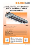
owner ’s manual
DEFINITION DC10A OWNER’S MANUAL_01
contents
WARRANTY
02CONNECTION IN SINGLE WIRE MODE
05
INTRODUCTION
03CONNECTION IN BI-WIRE MODE
06
WARNING, STRONG MAGNETIC FIELDS
03
06
TECHNOLOGY
03CONNECTION OF EARTH OR ‘GROUND’ LEAD 06
AMPLIFIER CHOICE
04
POSITIONING AND FINE-TUNING
06
CABLE CHOICE
04
PORT BUNGS
07
UNPACKING
04GRILLES 07
ACCESSORIES
04CARE OF CABINET
07
MASS LOADING
05TECHNICAL SPECIFICATIONS
08
FITTING PLINTHS AND FLOOR SPIKES
05SETUP DIAGRAMS
09-011
INSTALLATION 05
BI-AMPING
WARRANTY
No maintenance of this Tannoy product is necessary.
Please register your Tannoy product online at www.tannoy.com.
All of our products have been produced and tested with care and precision to give first-class service.
All passive components are guaranteed for a period of five years from the date of purchase from an authorised Tannoy dealer
subject to the absence or evidence of misuse, overload, or accidental damage.
All active and electronic components are guaranteed for a period of two years from the date of purchase from an authorised
Tannoy dealer subject to the absence of, or evidence of, misuse, overload or accidental damage.
If at any time during this warranty period the equipment proves to be defective for any reason other than accident, misuse,
neglect, unauthorised modification or fair wear and tear, we will repair any such manufacturing defect or, at our option,
replace it without charge for labour, parts or return carriage.
If you suspect a problem with a Tannoy product then, in the first instance, discuss it with your Tannoy dealer. If you require
further assistance then we ask that you deal directly with your local Tannoy distributor. If you cannot locate your distributor
please contact Tannoy Customer Services, at the address given below.
Customer Services, Tannoy Ltd., Rosehall Industrial Estate, Coatbridge, North Lanarkshire ML5 4TF, Scotland
Telephone:
+44 1236 420199
Fax: +44 1236 428230
E-mail: [email protected]
DO NOT SHIP ANY PRODUCT TO TANNOY WITHOUT PREVIOUS AUTHORISATION.
Our policy commits us to incorporating improvements to our products through continuous research and development.
Please confirm current specifications for critical applications with your supplier.
02_ DEFINITION DC10A OWNER’S MANUAL
INTRODUCTION
Thank you for selecting a Tannoy loudspeaker developed in the UK by our dedicated team of design engineers. They are
the choice of discriminating music lovers the world over. Musical excellence is designed into our loudspeakers from the
start. Careful selection of the very best components combined with strict quality control procedures in the production
process ensures this level of excellence is maintained.
To gain maximum performance from your Definition DC10As, please take time to read this owner’s manual in full before
installation. Once you have set up your new loudspeakers please complete and return the registration document or register
your product online at www.tannoy.com - this does not limit your legal rights.
Loudspeakers are electromechanical devices that ‘run-in’ through use; performance will therefore improve after an initial
period of 24hrs use. Once they have been further run-in over a longer period, there will be clear enhancement of the stereo
imaging, mid-band quality and bass performance characteristics.
We are confident that you will continue to enjoy your new Tannoy Definition DC10As for many years to come.
WARNING, STRONG MAGNETIC FIELDS
The powerful magnet system in the Definition DC10A will cause picture distortion with conventional CRT televisions and
monitors, and should not be used in the close proximity. There are no issues with plasma, LCD or LED televisions or
monitors.
TECHNOLOGY
Alcomax 3 Dual Concentric™
The time coherent, point source and constant directivity nature of the dispersion characteristics inherent in the Dual Concentric
drive unit makes it an accepted industry standard in studio monitoring. By exceeding the rigorous demands of the recording
and mastering environment Tannoy can ensure that playback performance is strictly controlled to accurately reflect the
sound engineer’s artistry. In nature all sounds emanate from a single point in space. The high frequency unit of the Dual,
centrally mounted in the throat of the main mid/bass driver, is so positioned as to acoustically replicate this single point
source; delivering an incredibly natural sound with a very wide imaging ‘sweet spot’ that creates an expansive soundstage
with remarkably focused placement of images.
The DC10A’s 10” Dual Concentric driver is derived from the classic Duals found in some of Tannoy’s most successful and
longest running Prestige series models. Powered by the highest quality Alcomax 3 Alnico motors, this classic driver magnet
material has exceptional field strength and is electrically conductive. This minimises non-linear voice coil inductive effects and
reduces micro distortions from eddy currents, leading to a sweet, natural and inherently coherent sound.
From instrument amplifiers to guitar pick-ups, Alnico is revered across the music industry for its musicality and dynamics as
well as its ability to resolve low level information and texture in the music. Tannoy has long used Alnico drivers in its range
topping loudspeakers to best reproduce every note and intonation that the musician intended - a realism rarely achieved by
ceramic ferrite motor systems.
The 10” Dual of the DC10A uses the latest iteration of Tannoy’s aluminium alloy tweeter with PepperPot WaveGuideTM.
Mid-and low-frequency reproduction is handled by a multi-fibre cone, allied to the Alcomax 3 magnet assembly engineered
to sit on the outside of the voice coils. This configuration delivers the greatest magnetic flux density across the poles,
employing to full effect the smoothness and musicality of the Alnico magnet system. Each DC10A driver is hand assembled
by Tannoy engineers before being tested and mounted into the cabinet with a unique bracing mechanism.
Audiophile Crossover
High-end components and a ‘simple straight’ philosophy combine to create a crossover with an ultra-clean signal path.
Low loss laminated core inductors ensure optimum LF performance while the HF networks audiophile-grade polypropylene
capacitors are acoustically damped using Tannoy ‘s Differential Materials Technology (DMTTM) material. Non inductive metal
film resistors are used in the high frequency feed. The Definition DC10A crossover sets the benchmark for signal integrity,
reproducing music with all the articulation and intelligibility of the original performance.
Deep Cryogenic Treatment
The entire crossover assembly is subject to revolutionary Deep Cryogenic Treatment (DCT), achieving unparalleled
gains in resolution and creating a more natural, cohesive sound. Using a proprietary process, the Definition DC10A crossover
is super-cooled to minus 190 degrees Celsius and returned to room temperature over a controlled period. This permanently
reduces internal stresses in the microstructure of the crossover’s component materials, leading to better signal transfer and
superior resolution of fine detail. One of the largest benefits is to the solder joints, which are traditionally an area of poor
crystalline structure.
DEFINITION DC10A OWNER’S MANUAL_03
AMPLIFIER CHOICE
Consult the product specification as this clearly shows the acceptable power range for amplifier matching to your speakers.
The high peak power handling of Tannoy loudspeakers permits responsible use with more powerful amplifiers - please read
the Warranty.
As with all loudspeaker systems, the power handling is a function of voice coil thermal capacity. Care should be taken to
avoid overdriving any amplifier, as this will cause output overload resulting in ‘clipping’ or distortion within the output signal.
This, if done for any extended period, will cause damage to the speakers.
Generally an amplifier of higher power that is running hard, but free of distortion, will do less damage to the loudspeaker than
a lower power amplifier continually clipping. Remember also that a high powered amplifier running at less than 90% of output
power generally sounds a great deal better than a lower powered example struggling to achieve 100%. An amplifier with
insufficient drive capability will not allow the full performance of the loudspeakers to be realised.
CABLE CHOICE
Always use the best quality of cable available within your budget. High quality audio signals passing from the amplifier to
the loudspeaker are unusual in their demands on the cable. Wide dynamic range and frequency bandwidth information
has to coexist with the ability to transmit peak currents of at least 10 amps, without incurring any loss or signal impairment.
This explains why the sound quality of the information reproduced by the loudspeakers is so dependent on the physical
properties of the cables connecting them to the amplifier.
We would recommend that you always keep the cable runs the same length for left and right speakers. Remember, cable
construction can affect the sound quality so be prepared to experiment to find a cable that suits your ear and audio system.
UNPACKING
To unpack the loudspeakers from their boxes remove tape from the top then fold the flaps right back before inverting the
carton and contents. Lift the carton clear of the contents then remove all inner packaging (See fig.1)
Check carefully for any sign of transit damage. In this unlikely event, notify your shipping company and/or dealer as soon
aspossible for advice.
It is recommended you store all the packaging to allow protected transport in future.
ACCESSORIES
Check the contents of each accessories box, as follows:
•
•
•
•
•
•
•
•
Plinth section, front x 1
Plinth section, rear x 1
Plinth mounting screws x 8
Floor coupling spikes x 4
Spike locking wheels x 4
Spike cups, for floor protection x 4
Spike adjustment hex tool x 1
Bi-wiring link cables x 4
Also:
• The front grille is provided in a separate pack within the carton x 1
• Foam port bungs, located in end packaging x 2
04_ DEFINITION DC10A OWNER’S MANUAL
MASS LOADING
These loudspeakers are designed to be mass loaded, if wished, to lower the centre of gravity and improve stability,
resulting in improved sound quality. To do so, remove the 4 screws securing the access plate to the bottom of the
loudspeaker. The loading volume can be filled with sand (which must be dry), or propriety materials available for such
purposes from your retailer. Feel free to experiment with the volume of loading material used, to achieve optimum bass
performance and stereo imaging. (See fig. 2)
FITTING PLINTHS & FLOOR SPIKES
Attach the two plinth sections using the screws and hex tool provided. These loudspeakers are designed to perform best
with the carpet piercing spikes fitted, for optimum stability. These are supplied, along with locking wheels, and should be
inserted into the threaded holes in the base of the cabinet. Level the speaker, using the hex tool and then tighten the locking
wheels firmly but without using undue force. Spike locating cups are provided in the accessory pack and these may be used
to protect sensitive floor surfaces. (Shown also in fig. 2)
Warning:
Ensure that the spikes are levelled and that the lock nuts are tightened firmly. The spikes should be pushed through the
carpet to locate into the flooring surface by applying pressure to the top of the cabinet. Failure to do so could render the
speaker unsteady and result in damage or injury should it be knocked over.
INSTALLATION
To avoid potential damage to your loudspeaker, ensure that the amplifier is switched OFF prior to connecting or
11
disconnecting any cables. Before switching on double check that all connections are secure and that polarity is correct.
CONNECTION IN SINGLE WIRE MODE
Using the supplied link cables, connect the high frequency (HF) and low frequency (LF) terminals respectively, as shown.
These must be removed to Bi-wire the speakers - see section entitled Connection in Bi-wire Mode. For optimum
performance in single wire mode, loudspeaker cable connections from the amplifier should be made to the high frequency
(HF) terminals of the loudspeaker: (See fig. 3)
• The positive (plus) terminal on the amplifier left channel (marked + or coloured red) must be connected to the positive HF terminal on the left speaker. The left speaker is the one on the left as you look at the stereo pair from your listening position.
• The negative (minus) terminal on the amplifier left channel (marked - or coloured black) must be connected to the negative HF terminal on the left speaker.
• Repeat this connection process for the right speaker. Remember that the positive (+ or red) on the amplifier must be connected to the positive (+ or red) on the speaker and the negative (- or black) to negative.
• Select a signal source, such as a CD player; switch on the amplifier and slowly turn up the volume control to
12
check that both loudspeakers are reproducing bass and treble information.
13
14
15
16
17
18
19
20
DEFINITION DC10A OWNER’S MANUAL_05
CONNECTION IN BI-WIRE MODE
Please note in Bi-wire mode that the link cables should not be used. (See fig. 4)
• If not using specially designed bi-wire cable, prepare the two sets of cabling for each ‘side’ of the system separately. Measure and cut four lengths of cable, two per speaker. Label two of the cable lengths Left LF and Left HF (low frequency and high frequency) then repeat this process for the right pair.
• If your amplifier is not equipped with separate output terminals for bass and treble information then, at the amplifier end of the cables, twist the Left LF+ (positive) and the Left HF+ (positive) together. Connect these to the amplifier Left channel positive terminal marked + (plus) or coloured red.
Twist the Left LF- (negative) and the HF- (negative) cables together and connect them to the amplifier Left channel negative terminal marked - (minus) or coloured black.
At the loudspeaker end connect the cables labelled Left LF+ and Left LF- to the left hand loudspeaker LF terminals, ensuring that you note the polarity markings on the cable sheathing.
Then proceed to connect the Left HF+ and Left HF- to the HF terminals on the same loudspeaker.
• Repeat this process to connect the right hand loudspeaker to the amplifier right channel output, once again ensuring that polarity is correct throughout.
• Switch the amplifier on with the volume control set at its lowest setting. Select a favourite source and slowly turn up the volume to a low level. Check that bass and treble information is being reproduced from both speakers - if not, switch off the amplifier and recheck the connections.
BI-AMPING
Bi-amping extends the principle of Bi-wiring one stage further. In this connection option separate power amplifiers are used
for bass and treble signals in each loudspeaker. Four mono (or two stereo) amplifiers of the same type are required for a
stereo pair of loudspeakers. Ensure that the cable links between the loudspeaker terminals are removed and that correct
polarity is maintained throughout.
If two stereo amplifiers are used, it is recommended that one amplifier supply bass information to left and right loudspeakers
and the other treble information. (See fig. 5)
CONNECTION OF EARTH OR ‘GROUND’ LEAD
Use of a shielded or screened loudspeaker cable will offer further performance advantages when used with the five-way
terminal panel. The screening termination should be connected to the earth or ground (white) terminal on the loudspeaker
and to the ground or earth connection on the amplifier. Alternatively if you are not using a screened loudspeaker cable but
wish to utilise the earthing facility, run a single cable between the earth or ‘ground’ (white) terminal on the loudspeaker to the
earth (ground) connection on the amplifier.
Avoid potential damage to your amplifier - ensure that all connections are secure and the polarity is correct in all wiring.
(Method illustrated on all terminal panel sketches)
POSITIONING AND FINE-TUNING
To get best results from your new Tannoy Definition DC10A loudspeakers, it is worthwhile spending a little time finding the
optimum set-up configuration.
Begin by angling the speakers towards your chosen listening position, usually this is on the centre line of the room, so that
when seated you can just see the inner side panel of each speaker. The front of the loudspeaker should not be obstructed
in any way. The loudspeakers should be located between 1.5 to 4.5 metres (5ft to 15ft) apart - with the listening position
set slightly further away than the speakers are apart. Avoid positioning the loudspeakers in corners of the room, as this will
have a negative effect on performance. Ideally, maintain a distance of at least 0.5 metres (20 inches) from the rear wall, and
1 metre (39 inches) from the side. (See fig. 6).
06_ DEFINITION DC10A OWNER’S MANUAL
PORT BUNGS
The Definition DC10A is designed to be operated normally without the foam port bungs in place. However if excessive or
poorly controlled bass output results from non-optimal positioning or adverse room acoustics, either one or both bungs
may be placed in the rear reflex ports, to damp low frequency output.
GRILLES
The front grille has been designed to provide acoustic transparency. However, for ultimate fidelity the enthusiast will
appreciate the slight improvement in clarity and detail that is achieved by removing the grilles during listening. The grilles
are held in place by hidden magnets to ensure a neat visual appearance.
CARE OF CABINET
The cabinets should only be cleaned with a dry cloth or with a light application of quality non-silicone furniture polish.
DEFINITION DC10A OWNER’S MANUAL_07
TECHNICAL SPECIFICATIONS
DC10A
Performance
Recommended amplifier power
(Watts RMS)
30 – 300 Continuous power handling
(Watts RMS)
150
Peak power handling (Watts)
600
Sensitivity (2.83 Volts @ 1m)
Nominal Impedance (ohms)
93 dB
Frequency response (-6 dB)
28 Hz – 22 kHz Dispersion (degrees conical)
90
8
Drive Units
Dual Concentric™ high frequency
51 mm (2”) Aluminium alloy dome,
Alnico magnet system with Pepperpot WaveguideTM
Dual Concentric™ low frequency
250 mm (10”) treated paper pulp cone with twin roll impregnated
fabric surround. 52 mm (2”) edge wound voice coil, Alnico magnet system
Crossover
Crossover frequency
Crossover Type
1.1 kHz
Bi-wired, hard wired passive low loss 2nd order LF,
2nd order compensated HF, Cryogenically treated
CABINET
Enclosure type
Twin Rear ported
Dimensions H x W x D
Inc plinth & grille
1135 x 345 x 438 mm
(44.69 x 13.58 x 17.24”)
Volume 103 Litres (3.64 cu. ft.)
Weight 42.7 kg (94.1 lbs)
08_ DEFINITION DC10A OWNER’S MANUAL
SETUP DIAGRAMS
Fig.1 Unpacking
Fig.2 Mass Loading, Fitting of Plinth & Spikes
DEFINITION DC10A OWNER’S MANUAL_09
Fig.3 Single Wire Mode
TO RIGHT
SPEAKER
- +
L
- +
R
POWER AMPLIFIER
TO 'GROUND' OR
'EARTH' CONNECTION
ON AMPLIFIER (OPTIONAL)
LINKS IN PLACE
Fig.4 Bi-Wire Mode
TO RIGHT
SPEAKER
-
+
L
-
+
R
POWER AMPLIFIER
TO 'GROUND' OR
'EARTH' CONNECTION
ON AMPLIFIER (OPTIONAL)
LINKS REMOVED
010_ DEFINITION DC10A OWNER’S MANUAL
Fig.5 Bi-Amp Mode
TO RIGHT
SPEAKER
- +
L
- +
R
HIGH FREQUENCY
POWER AMPLIFIER
LOW FREQUENCY
POWER AMPLIFIER
L
- +
R
- +
SPEAKER
TO RIGHT
LINKS REMOVED
Fig.6 Recommended Positioning
0.5 METRES OR MORE
1.5 TO 4.5 METRES
1 METRE
OR MORE
DEFINITION DC10A OWNER’S MANUAL_011
6481 0617 / 0812
Tannoy Limited - product designed and engineered in the United Kingdom. Tannoy adopts a policy of continuous improvement and product
specification is subject to change. Dual Concentric, Differential Materials Technology, WideBand, Tulip WaveGuide, are trademarks of Tannoy Limited.
All other trademarks remain the property of their respective owners. Copyright© 2012 Tannoy Limited. All rights reserved.
012_ DEFINITION DC10A OWNER’S MANUAL
tannoy.com