1
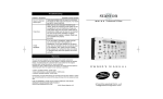
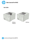
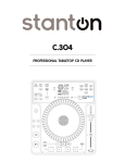
RM.404
Professional DJ Mixer
OWNER’S MANUAL
STANTON MAGNETICS, Inc.
[email protected]
©2004 Stanton Magnetics, Inc.
Please read carefully before use of this product
Failure to follow the instructions printed below may void warranty
• Follow all security advice printed on your mixer
• When removing the unit's AC plug from the power source, grasp
and pull the plug, NEVER the cord itself!
• Avoid placing your mixer near heat sources, such as power amplifiers.
• When in use, place your mixer on a stable surface, away from vibration.
Always use care when carrying your mixer. Impact, or heavy vibration may
compromise the unit's mechanical integrity. The manufacturer is not
responsible for damage resulting from an impact, or misuse.
• When in use, place your mixer away from sources of hum or noise, such
as transformers, or electric motors.
• To prevent overheating, always provide your mixer with adequate ventilation air space.
• Avoid stepping on your mixer's AC cord. Repeated compression of the
cord may lead to electrical shorting.
• To avoid damage due to AC voltage peaks, always disconnect your mixer
from the power source during electrical storms.
• Your mixer contains no user-serviceable parts except for the crossfader.
The manufactureris not responsible for any damage or personal injury
resulting from unauthorized user-servicing or modifications. In addition,
the warranty will be void if any unauthorized service by the user is detected. Always return you mixer to an authorized Stanton dealer for servicing.
Welcome
Congratulations and thank-you for purchasing the latest addition to the growing Stanton family. Sporting a new attitude, and a fresh, modern look, the
RM.404 is a 4-channel, rackmount mixer loaded with features and innovations giving club and mobile DJs a powerful, yet simple tool to mix, create,
and perform their best. 1/4" and 1/8" headphone outputs, XLR, RCA, and
1/4" Master and Zone outputs, plus plenty of inputs, including one Mic input,
and a separate 1/8" jack for connecting portable devices such as iPodsTM,
ensure the utmost in flexibility. Colored, backlit knobs, separate LED level
indicators, gain and 3-band EQs on every channel with a fully assignable
Crossfader, offer increased control and functionality. Thoughtfully designed
and engineered to give you the most intuitive and instinctual experience possible, the RM.404 delivers all these features in a logical layout with quality
components, all at an affordable price.
Stanton's revolutionary Superior Sound Technology (SST™) also gives the
RM.404 exceptional sound quality with audio specifications rivaling mixers
costing up to four times as much. Developed from the ground up by a team
of seasoned audio professionals who have designed world class professional recording studio and broadcast mixers, working hand in hand with experienced and respected DJs, SST™ delivers a dynamic range better than 110
dB through ultra low-noise circuitry with a lower total harmonic distortion
(THD) than other mixers in its class. Glass epoxy PC boards, surface mount
technology, and faders that don't bleed add to the superior construction standards. This equates to a cleaner, more transparent sound, allowing your
music to be heard the way it was meant to. We’re proud to bring you the new
look, feel and sound of Stanton.
RM.404 Top Panel (FUNCTIONS)
The controls and functions of the RM.404 are grouped in alphabetical sections (clockwise from upper right corner) for your reference and then listed
numerically for more detail.
Section A:
Section B:
Section C:
Section D:
Section E:
Section F:
Section G:
Output Meters
Output Controls
Cue Controls
Crossfader Controls
MP3 / Aux In
Mic Controls
Channel Controls
RM.404 Top Panel (FUNCTIONS)
Section A: Output Meters
1. Meter Switch: Switches the display of the Level Meter (#2) between
Master or Zone output signals.
2. Level Meter: Displays the left and right Master or Zone output level of the
mixer. Red indicates clipping.
RM.404 Top Panel (FUNCTIONS)
Section B: Output Controls
3. Master Level: Controls the overall output level of the audio signal sent
through the Master connectors (see Output Connections.)
4. Stereo/Mono Switch: Switches the Master output between a stereo or
mono signal. Mono mode can be used to accommodate some large PA systems. It can also be engaged in the event of a sudden loss of stereo signal
in phonograph cartridge connections [Stereo = UP position.]
5. Zone Level: Controls the output level of the audio signal sent through the
Zone connectors (see Output Connections.)
6. Master Pan: Controls left/right signal balance of the Master Output (#3.)
RM.404 Top Panel (FUNCTIONS)
Section C: Cue Controls
7. Split Cue: Controls how the CUE will be heard in the headphones. In the "stereo"
position, the pre-selected Cue (#29) will be heard as a stereo signal in the headphones (full stereo audio signal in both ears.) In "split" position, the pre-selected Cue
(#29) will be heard on one side of the headphones, while the Master Output (#3) signal is heard on the other side (different audio signals in each ear.)
8. Headphone Output 1: Connection for 1/4 inch headphone (phono-jack.)
Recommended headphone impedance is 32-200 ohms for maximum volume.
9. Headphone Output 2: Connection for 1/8 inch headphone (mini-jack.)
Recommended headphone impedance is 32-200 ohms for maximum volume.
10. Cue Level: Controls the overall headphone output level of both output jacks. It is
recommended that headphones with an impedance rating of 200 ohms or less be
used for maximum volume.
11. Cue Pan: This controls the blend of audio signals that can be heard in the headphones. In the left-most “Cue” position, only channels selected by the Cue Assign
switches (#29) will be heard. In the right-most “Master” position, only signals being
sent to the Master Output (#3) will be heard in the headphones. Any setting inbetween provides a mix of both Cue and Master signals. This gives DJs the flexibility to choose how they wish to monitor audio signals, based on personal preference
and technique.
RM.404 Top Panel (FUNCTIONS)
Section D: Crossfader Controls
12. Fader Start (A): Activates this side (A) of the Crossfader (#13) for use
with components with the Fader Start feature. Moving the crossfader away
from the left-most position will cause the device (CD / Turntable) to start playing. This allows DJs to activate a device by using the fader as if they were
pressing Play. [Fader Start compatible device (CD / Turntable) is required.
Fader Start cables need to be connected between the device and the appropriate input channel on the rear of the mixer].
13. Crossfader: Controls the audio signal that is sent to the Outputs (Section
B.) When the Crossfader is in the left-most position (A), only the channel(s)
set to (A) on their Crossfader Assign switch (#31) will be sent to the Outputs.
When the Crossfader is in the right-most position (B), only the channel(s) set
to (B) on their Crossfader Assign switch (#31) will be sent to the Outputs.
This allows DJs to fade (mix) or cut (scratch) between different audio signals.
When the Crossfader is somewhere in between the two extremes, a “blend”
or “mix” between two signals occurs. [Note: if NO line channel(s) have been
set to either A or B (using #31) then the Crossfader is bypassed. Also, if the
appropriate Channel Fader (Line Fader) (#30) is set to zero, no sound will be
output.]
14. Fader Start (B): Activates this side (B) of the Crossfader (#13) for use
with components with the Fader Start feature. Moving the crossfader away
from the right-most position will cause the device (CD / Turntable) to start
playing. This allows DJs to activate a device by using the fader as if they
were pressing Play. [Fader Start compatible device (CD / Turntable) is
required. Fader start cables need to be connected between the device and
the appropriate input channel on the rear of the mixer].
RM.404 Top Panel (FUNCTIONS)
Section E: MP3/Aux In
15. MP3 / Aux. Input: This 1/8" Mini-jack (3.5 mm) input was designed for
easy access and connectivity to a variety of portable devices (portable MP3
/ mini-disc / CD players / iPods.) Use this input instead of having to re-wire
the back panel of the mixer or use adapters.
Section F: Mic Controls
Section F: Mic Controls (continued)
16. Mic-1 XLR Input: Primary connection for a standard balanced (XLR)
microphone.
17. Mic-1 1/4" Input: Primary connection for a standard unbalanced (1/4")
microphone.
18. Mic Level: Controls the output level (volume) of Microphone 1 only (both
connections.)
19. Mic EQ (HIGH): Controls High frequency equalization for BOTH microphones (+10/-10 dB.) [Note: Any changes made to EQ settings will affect the
overall output level of the microphones.]
20. Mic EQ (MID): Controls Mid frequency equalization for BOTH microphones (+10/-10 dB.) [Note: Any changes made to EQ settings will affect the
overall output level of the microphones.]
21. Mic EQ (LOW): Controls Low frequency equalization for BOTH microphones (+10/-10 dB.) [Note: Any changes made to EQ settings will affect the
overall output level of the microphones.]
22. Mic Selector: Turns the mic(s) On or Off and activates the automatic
Talk-over circuit. When activated, the automatic talk-over circuit reduces the
music output allowing the mic to appear louder than the master audio signal.
RM.404 Top Panel (FUNCTIONS)
Section G: Channel Controls
23. Input selector switch: Selects phono or line input for the corresponding
channel. This is a three way switch allowing input from only one device at a
time (Phono or either of two Line level inputs (for connections in rear panel of
mixer see Sections L-O.))
24. Channel EQ (HIGH) : Controls High frequency equalization of corresponding channel (+9/-26 dB.) [Note: Any changes made to EQ settings will affect
the overall output level of this channel.]
25. Channel Gain: Controls the input level (GAIN) of the corresponding
channel. This control is Pre-EQ. Gain levels will differ between various types
of devices (such as turntables or CD players) or different types of media. The
Channel Gain allows DJs to compensate for these differences in order to
maintain consistent sound levels between different pieces of music, as well
as consistency between the different mixer channels. Be aware that turning
RM.404 Top Panel (FUNCTIONS)
Section G: Channel Controls (continued)
this setting too high may result in a loss of sound quality (distortion.)
[Note: For best results set this control in the number 7 (2 O'Clock) position for
unity gain. If further adjustment is needed, this is a good reference point.]
26. Channel EQ (MID) : Controls Mid frequency equalization of corresponding channel (+9/-26 dB.)
[Note: Any changes made to EQ settings will
affect the overall output level of this channel.]
27. Channel Input Meter: Displays the input level of this channel. The input
level is determined by the Channel Gain controls (see #25.) Red indicates
clipping.
28. Channel EQ (LOW) : Controls Low frequency equalization of corresponding channel (+9/-26 dB.) [Note: Any changes made to EQ settings will affect
the overall output level of this channel.]
29. Cue (assign) : Selects the channel to be monitored via headphone Cue
(Section C.)
30. Channel Fader (Line Fader) : Controls the output level of the corresponding channel. This control is Post-EQ and when NOT using Crossfader
Assign (#31 = bypass) the signal is sent directly to the Master Output.
31. Crossfader Assign (A-B- BYPASS) : Controls where the audio signal for
this channel will be sent; either to the Crossfader (#13) or to Master Output
(#3.) When set to A, this channel will be assigned to the left side of the
Crossfader. When set to B, this channel will be assigned to the right side of
the Crossfader. When set to BYPASS, the Crossfader will be bypassed altogether and the audio is sent straight from the Line Fader (#30) to the Master
Output (Section B.) [Note: This allows the DJ to mix with or without using the
Crossfader].
RM.404 Rear Panel (FUNCTIONS)
Section
Section
Section
Section
Section
Section
Section
Section
H:
I:
J:
K:
L:
M:
N:
O:
Power
Master Output
Zone Output
RCA Outputs
Channel 4 Inputs
Channel 3 Inputs
Channel 2 Inputs
Channel 1 Inputs
Section H: Power
H. Power Switch & Connection: This is the ON/OFF power switch for the
entire mixer. Only use the supplied adaptor (18v AC 1A) or one authorized by
a Stanton dealer or our service department (make sure the AC cable is properly secured by the screw connection.) In order to protect the RM.404 and
any equipment connected to it, make sure the unit is off before connecting the
power or making any other connections. In addition, make sure all volumes
are turned all the way down prior to following the proper power on/off
sequence. When turning on your system, turn the RM.404 on first, followed
by the rest of your equipment. When turning your system off, turn off the
RM.404 last.
RM.404 Rear Panel (FUNCTIONS)
Section I: Master Output
I. Master Output Connection: These Right & Left XLR connections are used
for the Master Output signal. Volume levels for this output are controlled by
the section B front panel controls. NOTE: The TRIM knob sets the maximum
volume allowed for this output (be sure it is set properly.) It should be used
in conjunction with the Master Fader (#3) as well as individual Gain (#25) and
Channel Faders (#30) when establishing optimal overall output for the
RM.404 and the sound system it is connected to. It is recommended to consult an audio professional during this process.
Section J: Zone Output
J. Zone Connection: These Right & Left output connections are used for a
secondary Master / Zone. Volume level for this output is controlled by section B front panel controls. Generally, this is used to connect to a pair of
Booth Monitors to facilitate precise mixing and level control. Alternatively, it
can be used to send sound to another part of the sound system (such as
another room), or another completely independent sound system.
Section K: RCA Outputs
K. RCA Output Connections (Master, Zone, & Record) : This group of
RCA connections are ALL outputs which correspond to the markings at the
right of the connection. The Master and Zone connections mirror the output
signals sent through sections (J) & (K). These are to be used when XLR or
1/4 inch connections are unavailable, as balanced XLR and 1/4 inch connections provide a cleaner signal than RCA connections. In order to record your
sets, connect an appropriate recording device to the “REC” outputs via RCA
cables. Volume levels for these outputs are also controlled by section B front
panel controls except for “REC” which is pre-master signal.
RM.404 Rear Panel (FUNCTIONS)
Section L: Channel 4 Inputs
L. Channel 4 Input Connections: This group of connections are ALL inputs
which are only routed to Channel 4 (select input using section G, (#23) from
top panel.) Only two lines (L4, L8) and one phono (PH4) OR MIC 3 can be
used as inputs here (the select switch located here toggles between PH4 and
MIC 3.) NOTE: Line inputs are used to connect to line level sources such as
CD players, samplers, tape players, etc. Phono inputs are used to connect
only to turntables. Mic inputs connect directly to microphones. To prevent
potential circuit damage, never connect line level source to phono inputs.
Section M: Channel 3 Inputs
M. Channel 3 Input Connections: This group of connections are ALL inputs
which are only routed to Channel 3 (select input using section G, (#23) from
top panel.) Only two lines (L3, L7) and one phono (PH3) OR CD can be used
as inputs here (the select switch located here toggles between PH3 / CD.)
The 1/8” connection is used only for connecting devices with the Fader Start
feature with the appropriate cables (to activate Fader Start for this channel
see Section D) NOTE: Line inputs are used to connect to line level sources
such as CD players, samplers, tape players, etc. Phono inputs are used to
connect to turntables. Mic inputs connect directly to microphones. To prevent
potential circuit damage, never connect line level source to phono inputs.
Section N: Channel 2 Inputs
N. Channel 2 Input Connections: This group of connections are ALL inputs
which are only routed to Channel 2 (select input using section G, (#23)) from
top panel.) Only two lines (L2, L6) and one phono (PH2) OR CD can be input
here (the select switch located here toggles between PH2 / CD.) The 1/8”
connection is used only for connecting devices with the Fader Start feature
with the appropriate cables (to activate Fader Start for this channel see
Section D) NOTE: Line inputs are used to connect to line level sources such
as CD players, samplers, tape players, etc. Phono inputs are used to connect
to turntables. Mic inputs connect directly to microphones. To prevent potential circuit damage, never connect line level source to phono inputs.
RM.404 Rear Panel (FUNCTIONS)
Section O: Channel 1 Inputs
O. Channel 1 Input Connections: This group of connections are ALL inputs
which are only routed to Channel 1 (select input using section G, (#23) from
top panel). Only one line (L1) and one phono (PH1) can be input here. The
“GND” connections are used only for phono inputs which require a Ground
cable and can be used for any phono input on any channel. NOTE: Line
inputs are used to connect to line level sources such as CD players, samplers, tape players, etc. Phono inputs are used to connect to turntables. Mic
inputs connect directly to microphones. To prevent potential circuit damage,
never connect line level source to phono inputs.
Application Example
This is a typical setup you’ll find in many nightclubs: 2 turntables, 2 CD players, plus a microphone for the DJ. Here’s how you would set up your equipment with the RM.404:
1. Be sure all equipment is powered “OFF” and all of the RM.404’s Channel
faders and Level knobs are at minimum volume.
2. Connect the turntables to the Phono inputs of Channels 1and 4. Be sure
the rear-panel toggle switch for Channel 4 is set to “PH2” or you won’t hear
anything. To avoid hum, don’t forget to connect the ground wires to the
grounding terminals.
3. Connect the CD players to the inputs of Channels 2 and 3.(if your CD player supports fader start connect applicable cables)
4. If you want to use the crossfader, set Channels 1 and 2 to “A” and
Channels 3 and 4 to “B”. Otherwise, set them all to “Bypass”.
5. Depending on the type of cable you have, connect your microphone to the
Mic 1 (1/4” / XLR) input.
6. Connect the Master Output jacks to the club’s power amp, EQ or
crossover. Then connect your monitor amp to the Booth output. If you have a
separate amp for a particular area of the club, connect this amp to the Zone
outputs.
7. Set the Input Selectors on the front panel to the appropriate inputs for each
channel.
8. Power everything up and carefully adjust the input levels using the Input
Gain knobs and Mic Level knob.
9. Slowly raise the Channel faders, Master fader, Booth level, Zone level and
Mic level as appropriate and start mixing!
Superior Sound Technology
The audio quality of the RM.404 is nothing short of revolutionary for DJ mixers in its price class. The RM.404 was designed by Stanton’s new product
development team, seasoned audio professionals who have designed world
class professional recording studio and broadcast mixers and product managers who are working DJs and work closely with some of the world’s most
respected DJs. They have taken their knowledge and experience to create
the RM.404, a DJ mixer with superior audio quality and unprecedented value.
Come hear the difference!
Technical Specifications
Line Inputs.................................................................................7 x 2 (RCA) , -10 dBV / >10 kOhm
1 (1/8” stereo mini-jack), 10 dBV / >10kOhm
Phono / CD Inputs...................................2 x 2 (RCA), -46 dBV / -10 dBV / 47 kOhm / >10 kOhm
Phono..............................................................................1 x 2 (RCA), -46 dBV (Phono) / 47 kOhm
Phono / Mic Input..................................1 x 2 (RCA), -46 dBV (Phono) 1 x (_ inch)–46 dBV (Mic)
Mic Input....................................................................................1 (XLR or _”) -46 dBV / 2.4 kOhm
Master Outputs............................................................2 (XLR) balanced/ 1 x 2 (RCA) unbalanced
-2 dBu balanced / -10 dBV unbalanced
Zone Outputs................................................................2 (1/4”) balanced /1 x 2 (RCA) unbalanced
-2 dBu balanced/ -10 dBV unbalanced
Record Output............................................................................1 x 2 (RCA) unbalanced / -10 dBV
Headphone Output...........................................1(1/4 inch), 1 (1/8 inch) greater than 32 Ohm load
Frequency Response.............................................................................20 Hz to 20 kHz +/- 1.5 dB
EQ Mic...........................................................................................3 band +10 dB (Baxandall Type)
Channel.........................................................................3 band +9 dB/-26 dB (Baxandall Type)
Noise Floor
Line in to Unbalanced Output...........................................................................................< -92 dBV
Line In to Balanced Output................................................................................................< -88 dBu
Crosstalk*
Line to Phono Line to Line....................................................................................< -90 dB at 1 kHz
Phono to Line........................................................................................................< -88 dB at 1 kHz
Fader Kill (Channel and Crossfader)....................................................................< -90 dB at 1 kHz
Max Output Level:
(Unity Gain- Line Input)...................................................................................+18 dBV Unbalanced
+24 dBu Balanced Outputs
S/N Ratio Line
(Ref to Max. Level)DynamicRange....................................................................................> 110 dB
T.H.D+N..............................................................................................................< 0.005% at 1 kHz
Dimensions (LxWxD).........18.9 in. x 8.7 in. x 5.25 in. (48 cm. x 22 cm. x 13 cm.) 5U rack spaces
* Input without signal terminated with dummy plug.
REPLACEMENT PARTS
Faders:
Crossfader:
CF404
Power Supply:
110v PS16US (North & Central America and parts of South America)
220v PS16EU (Europe, Parts of Asia and South America and Rest of World)
240v PS16UK (U.K.)
To replace the cross or channel faders, follow step 1 of the cleaning instructions. Replacement
parts are available from Stanton or your local Stanton dealer.
Troubleshooting
Problem / Symptom
No Sound
No Sound- Master
Output (Booth and
Zone are OK)
Possible Cause/ Solution
Is the power on? Check the power switch. Make
sure the channels are assigned properly to the
crossfaders. Make sure INPUT GAIN is turned up
and output level control is turned up. Depending
on the input, check the rear panel selector
switches. Check the top panel channel selector
switches.
Make sure that MASTER TRIM on the rear
panel is turned up.
No Sound
Headphones
Do the headphones work with the CUE pan in the
PROGRAM position but not PFL? If so, make
sure that the channel PFL switches are engaged.
Check the CUE LEVEL control.
Signal level is low
even with the
faders and input
level controls
turned up.
Check to make sure the talk switch is NOT
engaged on the microphone input.
Mixer sounds noisy
Check to make sure that the microphone levels
are turned all of the way down if a microphone is
not being used.
Microphone doesn’t
work
Is the Mic gain turned up? Does the microphone
require phantom power? This mixer does not
provide microphone phantom power.
Sound is distortedLine or CD input
In general, turn down the INPUT GAIN CONTROL.
The input signal may be too loud for the input gain
control setting that you were using. If the distortion
goes away, then you need to turn down the INPUT
GAIN CONTROL.
Troubleshooting
Problem / Symptom
Possible Cause/ Solution
Sound is distorted
Phono Input
Only plug turntables into this input, do not plug in CD
players or other Line Level sources. Turn down the
INPUT GAIN CONTROL
I hear hum.
Make sure you are using good shielded audio cables.
Some less expensive audio cables can be susceptible to
hum and interference. Keep your audio cables away
from AC power cables and AC transformers. Make sure
the mixer is not mounted too close to high power amplifiers or lighting equipment power supplies or ballasts.
Make sure your turntables are properly
grounded.
I hear
feedback
If you are using a microphone, make sure that you are
not too close to the speakers or headphones. If you hear
feedback on the phono input, then the turntable may be
mounted too close to the speakers. Also, make sure the
turntable base is placed on a surface that does not
vibrate or resonate easily when the speakers are turned
up loudly.
Warranty
Stanton Magnetics, Inc. – Warranty Provision – Returns for Repairs or Replacement
Warranty
Through Stanton’s authorized dealers around the World, Stanton, or one of Stanton’s authorized distributors outside the U.S., will, without charge, repair or replace, at the sole discretion of the entity
responsible for making the repair or providing the replacement, any Stanton merchandise proved
defective in material or workmanship for a period of one (1) year (three (3) years for C.D. players) following the date of original purchase. Exceptions to this warranty are as noted below:
The warranty for mechanical parts which are subject to wear and tear are limited to the earlier to occur
of thirty (30) days following the date of original purchase or the following number of cycles: Faders 15,000; Rotary potentiometers - 10,000; and Switches - 10,000.
Stanton will warrant all replacement parts and repairs for ninety (90) days from the date of original shipment. Repairs made necessary by reason of misuse, alteration, normal wear, or accident are not covered under this warranty.
Returns
Authorized Stanton dealers are only authorized to sell and distribute merchandise within a specific
country. All goods requiring warranty repair or replacement must be returned (freight prepaid if not
hand-delivered) to the authorized Stanton dealer from whom the merchandise was purchased and in
the same country where the merchandise was purchased. For purposes of purchases made via the
Internet, the merchandise must be returned to the authorized Stanton dealer in the country where the
authorized Stanton dealer which sold the merchandise to purchaser is located and not the authorized
Stanton dealer in the country where the purchaser is located or the country in which the merchandise
was received. Any returns to a non-authorized dealer or to an authorized Stanton dealer not in the same
country as the merchandise was intended to be sold or as set forth above will void this warranty.
To initiate a warranty repair, you must contact the authorized Stanton dealer from whom you purchased
the merchandise, and follow such authorized Stanton dealer’s return policy.
Stanton assumes no risk and shall be subject to no liability for damages or loss resulting from the specific use or application made of the merchandise. Stanton's liability for any claim, whether based on
breach of contract, negligence, infringement of any rights of any party, or product liability, and relating
to the merchandise shall not exceed the price received by Stanton from your purchase of such merchandise. In no event will Stanton be liable for any special, incidental or consequential damages
(including loss of use, loss of profit and claims of third parties) however caused, whether by the negligence of Stanton or otherwise. To the extent permitted by law and except as otherwise provided above,
Stanton disclaims any express or implied warranties of merchantability or fitness for a particular purpose.
The above warranty provides you with specific legal rights. You may also have additional rights, which
are subject to variation from state to state and country to country.
If there is a dispute regarding the warranty of merchandise that does not fall under the warranty conditions stated above, please include a written explanation with the merchandise when returned pursuant
to the terms and conditions set forth herein.
Please register your product online at www.stantondj.com or mail your completed warranty card to:
Stanton Magnetics, Inc, 3000 SW 42 St. Hollywood, Florida 33312.