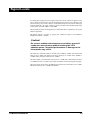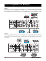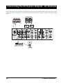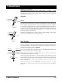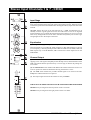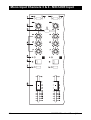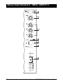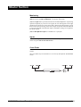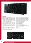
1
SOUNDCRAFT
User Guide
© Harman International Industries Ltd. 1996,1997
All rights reserved
Parts of the design of this product may be protected by worldwide patents.
Part No. ZM0143 Issue 3
Soundcraft is a trading division of Harman International Industries Ltd.
Information in this manual is subject to change without notice and does not
represent a commitment on the part of the vendor. Soundcraft shall not be liable
for any loss or damage whatsoever arising from the use of information or any
error contained in this manual.
No part of this manual may be reproduced, stored in a retrieval system, or
transmitted, in any form or by any means, electronic, electrical, mechanical,
optical, chemical, including photocopying and recording, for any purpose
without the express written permission of Soundcraft.
It is recommended that all maintenance and service on the product should be
carried out by Soundcraft or its authorised agents. Soundcraft cannot accept any
liability whatsoever for any loss or damage caused by service, maintenance or
repair by unauthorised personnel.
Harman International Industries Ltd.
Cranborne House,
Cranborne Road,
Cranborne Industrial Estate,
Potters Bar,
Herts.,
England.
EN6 3JN.
Tel:
Fax:
01707 665000
01707 660482
Table of Contents
1. Introduction
1.1
Introduction
1.2
Front Panel
1.3
Warranty
1.4
2. Installation
2.1
Dimensions
2.2
Installation
2.3
Precautions and Safety Instructions
2.4
Signal Levels
2.5
Connecting The Inputs
2.6
Connecting The Outputs
2.7
Connections
2.9
3. System Block Diagram
3.1
System Block Diagram
3.2
4. Functional Descriptions
4.1
Stereo Input Channels 1 & 7 - CD/AV
4.2
Stereo Input Channels 2 & 6 - VINYL/CD
4.3
Mono Input Channels 3 & 4 - MIC/LINE Input
4.4
Stereo Input Channel 5 - VINYL 3/INPUT C
4.6
Master Section
4.8
5. Specifications
5.1
Typical Specifications
5.2
i
ii
1. Introduction
D-MIX500 Introduction
1.1
Introduction
With a wide variety of choices in both inputs and outputs, the D-MIX500 delivers
class-leading flexibility in a cost effective package. A total of seven input channels,
four main stereo, one auxiliary stereo and two mono, each with two inputs, will handle
up to ten stereo input sources. To keep the DJ fully informed of selected signal sources
and outputs, coloured LEDs accompany every major switch on the front panel. Both
professional and consumer CD output levels are catered for, and three RIAA equalised
phono inputs accommodate turntable pickups.
The D-MIX500 is designed as a high performance mixer for the professional DJ. Front
panel controls are kept to a minimum to give a clear and uncluttered appearance while
providing sufficient flexibility and choice to meet individual requirements.
The design of the mixer allows for a choice of installations from standard 19" rack
mountings, occupying 7U of height, to free standing use on a desk top or table.
All connections are on the rear panel of the mixer for easy access once installed.
Channels
The D-MIX500 contains a variety of channels as follows:
Two Mono Mic/Line Input channels with insert point and 3-band EQ.
Five Stereo Input channels, with two switched stereo sources and a 3-band EQ.
A Master section containing main outputs, monitoring, master faders and metering.
Metering
The mixer is fitted with three meters:
Main Left and Right outputs.
Cue Mix.
Power Supplies
The console requires the D-MIX500 power supply.
Part No.
HB0166
HB0167
HB0169
1.2
Voltage
120V
230V
220V
D-MIX500 Introduction
CD2
Front Panel
D-MIX500 Introduction
1.3
Warranty
1
Soundcraft is a trading division of Harman International Industries Ltd .
End User means the person who first puts the equipment into regular
operation.
Dealer means the person other than Soundcraft (if any) from whom the End
User purchased the Equipment, provided such a person is authorised for this
purpose by Soundcraft or its accredited Distributor.
Equipment means the equipment supplied with this manual.
2
If within the period of twelve months from the date of delivery of the
Equipment to the End User it shall prove defective by reason only of faulty
materials and/or workmanship to such an extent that the effectiveness and/or
usability thereof is materially affected the Equipment or the defective
component should be returned to the Dealer or to Soundcraft and subject to the
following conditions the Dealer or Soundcraft will repair or replace the
defective components. Any components replaced will become the property of
Soundcraft.
3
Any Equipment or component returned will be at the risk of the End User
whilst in transit (both to and from the Dealer or Soundcraft) and postage must
be prepaid.
4
This warranty shall only be available if:
a) the Equipment has been properly installed in accordance with instructions
contained in Soundcraft’s manual; and
b) the End User has notified Soundcraft or the Dealer within 14 days of the
defect appearing; and
c) no persons other than authorised representatives of Soundcraft or the Dealer
have effected any replacement of parts maintenance adjustments or repairs to
the Equipment; and
d) the End User has used the Equipment only for such purposes as Soundcraft
recommends, with only such operating supplies as meet Soundcraft’s
specifications and otherwise in all respects in accordance Soundcraft’s
recommendations.
5
Defects arising as a result of the following are not covered by this Warranty:
faulty or negligent handling, chemical or electro-chemical or electrical
influences, accidental damage, Acts of God, neglect, deficiency in electrical
power, air-conditioning or humidity control.
6.
The benefit of this Warranty may not be assigned by the End User.
7.
End Users who are consumers should note their rights under this Warranty
are in addition to and do not affect any other rights to which they may be
entitled against the seller of the Equipment.
1.4
D-MIX500 Introduction
2. Installation
D-MIX500 Installation
2.1
Dimensions
2.2
D-MIX500 Installation
Installation
The D-MIX500 is designed for reliability and high performance, and is built to the
highest standards. Whilst great care has been taken to ensure that installations are made
as troublefree as possible, care taken at this stage, followed by correct setting up will
be rewarded by a long life and reliable operation.
Wiring Considerations
(A) For optimum performance it is essential for the earthing system to be clean and
noisefree, as all signals are referenced to this earth. A central point should be decided
on for the main earth point, and all earths should be ’star-fed’ from this point. It is
recommended that an individual earth wire be run from each electrical outlet, back to
the system star point to provide a safety earth reference for each piece of equipment.
(B) Install separate mains outlets for the audio equipment, and feed these independently
from any other equipment.
(C) Avoid locating mains distribution boxes near audio equipment, especially tape
recorders, which are very sensitive to electromagnetic fields.
Power Supply
Always ensure that you use the correct PSU for your mixer The D-MIX500 uses a
D-MIX500 power supply. There are three different PSU voltages for different
geographical areas.
Part No.
HB0166
HB0167
HB0169
USA
UK
EUR
Voltage
120V
230V
220V
Warning!
Before switching on your D-MIX500 console, check that
the power supply unit is the correct one for your area.
D-MIX500 Installation
2.3
Precautions and Safety Instructions
General Precautions
Avoid storing or using the mixing console in conditions of excessive heat or cold,or in
positions where it is likely to be subject to vibration, dust or moisture. Do not use any
liquids to clean the fascia of the unit: a soft dry brush is ideal. Solvents may cause
damage to paint or plastic parts.
Avoid using the console close to strong sources of electromagnetic radiation (e.g video
monitors, high power electric cabling): this may cause degradation of the audio quality
due to induced voltages in connecting leads and chassis. For the same reason, always
site the power supply away from the unit.
Caution!
In all cases, refer servicing to qualified personnel.
Handling and Transport
The console is supplied in a strong carton. If it is necessary to move it any distance after
installation it is recommended that this packing is used to protect it. Be sure to
disconnect all cabling before moving. If the console is to be regularly moved we
recommend that it is installed in a foamlined flightcase. At all times avoid applying
excessive force to any knobs, switches or connectors.
Power Supplies & Cables
Always use the power supply and cable supplied with the mixer: the use of alternative
supplies may cause damage and voids the warranty; the extension of power cables may
result in malfunction of the mixing console.
Warning!
Always switch the power supply off before connecting or
disconnecting the mixer power cable, removing or
installing the Cross Fader, and servicing. In the event of
an electrical storm, or large mains voltage fluctuations,
immediately unplug from the mains.
2.4
D-MIX500 Installation
Signal Levels
It is important to supply the correct input levels to the console, otherwise signal to noise
ratio or distortion performance may be degraded; and in extreme cases, damage to the
internal circuitry may result. Likewise, on all balanced inputs avoid sources with large
common-mode DC, AC or RF voltages, as these will reduce the available signal range
on the inputs. Note that 0dBu=0.775V RMS.
The microphone inputs are designed for use with balanced low impedance (150 or 200
ohms) microphones.
The Phones output is a 3-pole "A" gauge jack, suitable for high or low impedance
headphones (8ohms - 2kohms).
Caution!
Do not use unbalanced microphones or battery powered
condenser microphones without isolating the +48V
phantom power: degraded performance or damage to the
microphone may result.
The sensitivity of the Mic inputs is variable from -15dBu to -50dBu, with a maximum
input level of +4dBu. The Mono Line Input sensitivity is variable from -20dBu to
+15dBu with a maximum input level of +30dBu.
The Stereo Input is provided with a gain trim of +/-10dB, with a maximum input level
of +32dBu for CD or AV inputs. Vinyl inputs are suitable for moving magnet cartridges.
The main outputs of the mixer (Left/Right) are balanced at a nominal level of +4dBu.
Maximum output level is +26dBu into 5kohms.
D-MIX500 Installation
2.5
Connecting The Inputs - Examples
Example 1
In this example, 2 CD players are connected: one each to channels 1 and 7. There is also a turntable connected to channel
5. The DJ’s mic would normally be plugged into mic 1 (channel 3) via the front panel, and is therefore not shown in this
diagram; an additional mic shown is connected to mic 2 (channel 4). This may be used by, for example the MC. Finally
there is an Effects unit and a limiter/compressor connected to the FX insert point: these would be used by the mic channels.
Example 2
In this example, 2 turntables are connected: one each to to channels 2 and 6. There is also a CD player connected to channel
5. The DJ’s mic would normally be plugged into mic 1 (channel 3) via the front panel, and is therefore not shown in this
diagram. Other options may include a Cassette Deck connected to channel 7, and a Video Disk Player connected to channel
1, for example.
2.6
D-MIX500 Installation
Connecting The Outputs - An Example
In the example below, a 2-channel graphic equaliser is connected to the main outputs’ insert points. The main outputs are
driving power amps, with speakers on the main dance floor. A secondary dance floor is served by power amps and speakers
which are driven by the stereo 2 outputs. A bar or foyer area may have a mono amp and speaker which is, in the example
shown, fed from the mono 1 output.
D-MIX500 Installation
2.7
Connecting the DJ System Outputs - An Example
In the example below, the DJ booth amps and speakers are shown fed from the Booth outputs. There is also a tape recorder
to record the console’s output, this is connected to the record sockets. Finally, a lighting controller is fed from the lights
output.
2.8
D-MIX500 Installation
Connections
Wiring conventions
The D-MIX500 uses various different types of audio connector: 3-pin XLR , 1⁄4" 3-pole
jacks and RCA phono connectors. This section describes how to connect external
equipment to the console. Correctly-made cables of the proper type will ensure peak
performance from your mixer.
Inputs
2. Hot(+ve)
3. Cold(-ve)
1. Screen
Balanced
Input
The mic input accepts XLR-type connectors and is designed to suit a wide range of
BALANCED or UNBALANCED low-level signals. Professional dynamic, condenser
or ribbon mics are best because these will be LOW IMPEDANCE. While you can use
low-cost HIGH IMPEDANCE mics, you do not get the same degree of immunity to
interference on the microphone cable and as a result the level of background noise may
be higher. If you turn the PHANTOM POWER on, the socket provides a suitable
powering voltage for condenser mics.
DO NOT use unbalanced sources with the phantom power switched on. The voltage
on pins 2 & 3 of the XLR may cause serious damage.
2. Hot(+ve)
Link 3
to 1
XLRs
1. Screen
Unbalanced
Input
Jack Sockets
The 1/4" input jacks on this console fall into one of two categories: balanced inputs
and unbalanced inputs. The diagram on the left shows the connections for both types.
The following input jack sockets are balanced:
Balanced
Unbalanced
Hot (+ve)
Signal
Cold (-ve)
Gnd/Screen These
Gnd/Screen
Gnd/Screen will
Tip
Ring
AV1 Left, AV1 Right, Input A, Input B, AV2 Left, AV2 Right, Main Output Insert
Return Left and Main Output Insert Return Right.
Sleeve
inputs accept 3-pole 1/4" "A" gauge (TRS) jacks, or 2-pole mono jacks which
automatically ground the "cold" input.
These inputs are BALANCED for low noise and immunity from interference, but you
can use UNBALANCED sources by wiring up the jacks as shown left, although you
should then keep the cable lengths as short as possible to minimise interference pick-up
on the cable. Note that the ring must be grounded (by linking it to the sleeve ) if the
source is unbalanced.
The FX Insert Return jack socket is unbalanced. It will accept a 3-pole 1/4" "A" gauge
(TRS) jack, or a 2-pole mono jack. It you use a 3-pole jack, the ring must be linked to
the sleeve.
D-MIX500 Installation
2.9
Connections
Phono Plugs
The phono plug inputs are all unbalanced.
The phono inputs are as follows:
CD1 Left, CD1 Right, CD2 Left CD2 Right, CD3 Left, CD3 Right CD4 Left, CD4
Signal Right, Vinyl1 Left, Vinyl1 Right, Vinyl2 Left, Vinyl2 Right, Vinyl3 Left, Vinyl3
Right,Input C Left, Input C Right, Monitor Left and Monitor Right.
Gnd/Screen
The vinyl inputs have RIAA equalisers for turntables.
Outputs
XLRs
The left and right main outputs are on 3-pole male XLR connectors, wired as shown
on the left. They are balanced outputs, allowing long cable runs to balanced amplifiers
or other equipment. If the amplifier (or other equipment) which you are using has an
unbalanced input, you should wire the output from the D-MIX500 as shown in the
’Balanced To Unbalanced’ diagram below.
1. Screen
3. Cold
(signal -ve)
2. Hot
(signal +ve)
Balanced
Output
Signal +
Balanced To Balanced
External Device
Input
D-MIX 500
Balanced Output
Screen
Signal -
Screen not connected
at external device end
Chassis Earth
Mains Earth
Signal +
Balanced To Unbalanced
Input
D-MIX 500
Balanced Output
External Device
Input
Screen
Chassis Earth
Signal Experience has shown that sometimes it is better
not to connect screen at external device end
Mains Earth
2.10
D-MIX500 Installation
Connections
Jack Sockets
Signal +
Impedance
Balanced Gnd
Gnd
All of the jack socket outputs are impedance balanced. They are on 3-pole a gauge jack
sockets, wired as shown on the left and below,. They accept 3-pole 1/4" "A" gauge
(TRS) jacks, or 2-pole mono jacks.
The jack socket outputs are as follows:
FX Insert Send, Main Output Insert Send Left, Main Output Insert Send Right, Stereo
2 Left, Stereo 2 Right, Mono1, Mono2, Booth Left, Booth Right and Sound-to-Light.
Signal +
Impedance Balanced To Balanced
Signal +
D-MIX 500
Impedance Balanced Output
External Device
Input
Signal -
Screen
Imp.Bal. Gnd
Screen not connected
at external device end
Chassis Earth
Mains Earth
Impedance Balanced To Unbalanced
Input
Signal +
D-MIX 500
Impedance Balanced Output
External Device
Input
Screen
Chassis Earth
Imp.Bal. Gnd
Experience has shown that sometimes it is better
not to connect screen at external device end
Mains Earth
Phono Sockets
The Record Left and Record Right output phone sockets are, of course, both unbalanced
outputs. See the diagram below for details of how to connect to an external tape
machine.
Gnd/Screen
Signal
Signal
Unbalanced To Balanced
Signal +
External Device
Input
Signal -
D-MIX 500
Unbalanced Output
Screen
Screen not connected
at external device end
Chassis Earth
Mains Earth
Unbalanced To Unbalanced
Signal
Input
External Device
Input
D-MIX 500
Unbalanced Output
Screen
Chassis Earth
Mains Earth
D-MIX500 Installation
If the mains earth is isolated from external device
ground, then connect shield at both ends
2.11
2.12
D-MIX500 Installation
3. System Block Diagram
D-MIX500 System Block Diagram
3.1
System Block Diagram
3.2
D-MIX500 System Block Diagram
4. Functional Descriptions
D-MIX500 Functional Description
4.1
Stereo Input Channels 1 & 7 - CD/AV
Input Stage
(1) The input switch selects the Input source. When this switch is pressed AV 1(2) has
been selected and the LED to the right of the switch lights up orange. When the switch
is released a green LED will illuminate thus meaning the CD 1(2) Input source has been
selected.
(2) Gain- Adjusts the level of the selected input by +/-10dB, and should be set up
carefully to ensure a good signal level to the rest of the mixer. If it is set too high the
signal will distort as it overloads the channel and causes clipping. If it is set too low the
level of any background hiss will be more noticeable and you may not be able to get
enough signal level to the output of the mixer.
Equalisation
(3) The Equaliser (EQ) allows precise manipulation of the sound.
Three EQ bands are provided, HF (High Frequency), MF (Mid Frequency) and LF
(Low Frequency). These EQ bands provide 15dB of cut and boost at 10kHz, 1kHz and
80Hz respectively on the D-MIX500; 5dB cut and boost at these frequencies on the
D-MIX500L.
Channel Output
(4) The Peak LED warns the DJ of excessive signal level in the channel 6dB before
clipping occurs. The signal is sampled just after the EQ section, and illumination of the
LED will indicate that the input sensitivity is set too high, or that the EQ settings are
too extreme.
(5) The Channel ON switch enables and disables the channel. When the switch is set
to the on position an LED will illuminate showing the channel is active.
(6) The CUE switch enables the pre-fade channel signal to be routed to the DJ’s
headphones and booth monitors if required.
(7) The Output signal level from the channel is set by the Fader.
THE OUTPUT OF THESE CHANNELS MAY BE ASSIGNED TO THE CROSS FADER.
Channel 1 may be assigned to the left position of the cross fader.
Channel 7 may be assigned to the right position of the cross fader.
4.2
D-MIX500 Functional Description
Stereo Input Channels 2 & 6 - VINYL/CD
Input Stage
(1) The input switch selects the Input source. When this switch is pressed CD 4(3) has
been selected and the LED to the right of the switch lights up orange. When the switch
is released a green LED will illuminate thus meaning the VINYL 1(2) input source has
been selected.
(2) Gain- Adjusts the level of the selected input by +/-10dB and should be set up
carefully to ensure a good signal level to the rest of the mixer. If it is set too high the
signal will distort as it overloads the channel and causes clipping. If it is set too low the
level of any background hiss will be more noticeable and you may not be able to get
enough signal level to the output of the mixer.
Equalisation
(3) The Equaliser (EQ) allows precise manipulation of the sound.
Three EQ bands are provided, HF (High Frequency), MF (Mid Frequency) and LF
(Low Frequency). These EQ bands provide 15dB of cut and boost at 10kHz, 1kHz and
80Hz respectively on the D-MIX500; 5dB cut and boost at these frequencies on the
D-MIX500L.
Channel Output
(4) The Peak LED warns the DJ of excessive signal level in the channel 6dB before
clipping occurs. The signal is sampled just after the EQ section, and illumination of the
LED will indicate that the input sensitivity is set too high, or that the EQ settings are
too extreme.
(5) The Channel ON switch enables and disables the channel. When the switch is set
to the on position a green LED will illuminate showing the channel is active.
(6) The CUE switch enables the pre-fade channel signal to be routed to the DJ’s
headphones and booth monitors if required.
(7) The Output signal level from the channel is set by the Fader.
THE OUTPUT OF THESE CHANNELS MAY BE ASSIGNED TO THE CROSS FADER.
Channel 2 may be assigned to the left position of the cross fader.
Channel 6 may be assigned to the right position of the cross fader.
D-MIX500 Functional Description
4.3
Mono Input Channels 3 & 4 - MIC/LINE Input
4.4
D-MIX500 Functional Description
Mono Input Channels 3 & 4 - MIC/LINE Input
Input Stage
(1) The input switch selects the input source. When this switch is pressed INPUT A(B)
has been selected and the LED to the right of the switch lights up orange. When the
switch is released a green LED will illuminate thus meaning the MIC 1(2) input source
has been selected.
(2) Gain- Adjusts the level of the selected input, and should be set up carefully to ensure
a good signal level to the rest of the mixer. If it is set too high the signal will distort as
it overloads the channel and causes clipping. If it is set too low the level of any
background hiss will be more noticeable and you may not be able to get enough signal
level to the output of the mixer.
(3) A mix of the outputs of channels 3 and 4 feeds the FX INSERT SEND jack on the
rear of the console. Here the signal may be run through any kind of processor and back
into the console via the FX INSERT RETURN jack socket. When the FX switch is
pressed, the signal from the RETURN jack is routed to the console Master section.
Make sure the channels you wish to send to FX are ON.
Equalisation
(4) The Equaliser (EQ) allows precise manipulation of the sound, particularly to
improve the sound of microphone sources where the original sound is often far from
ideal.
Three EQ bands are provided, HF (High Frequency), MF (Mid Frequency) and LF
(Low Frequency). These EQ bands provide 15dB of cut or boost at 10kHz, 2.5kHz and
160Hz respectively on the D-MIX500; 5dB cut and boost at these frequencies on the
D-MIX500L.
Channel Output
(5) The Peak LED warns the DJ of excessive signal level in the channel 6dB before
clipping occurs. The signal is sampled just after the EQ section, and illumination of the
LED will indicate that the input sensitivity is set too high, or that the EQ settings are
too extreme.
(6) The Channel ON switch enables and disables the channel. When the switch is set
to the on position a green LED will illuminate showing the channel is active.
(7) The CUE switch enables the pre-fade channel signal to be routed to the DJ’s
headphones and booth monitors if required.
(8) The Output signal level from the channel is set by the Fader.
THE OUTPUT OF THESE CHANNELS CANNOT BE ASSIGNED TO THE
CROSS FADER
D-MIX500 Functional Description
4.5
Stereo Input Channel 5 - VINYL 3/INPUT C
4.6
D-MIX500 Functional Description
Stereo Input Channel 5 - VINYL 3/INPUT C
Input Stage
(9) The input switch selects the input source. When this switch is pressed INPUT C has
been selected and the LED to the right of the switch lights up orange. When the switch
is released a green LED will illuminate thus meaning the VINYL 3 Input source has
been selected.
(10) Gain- Adjusts the level of the selected input by +/-10dB and should be set up
carefully to ensure a good signal level to the rest of the mixer. If it is set too high the
signal will distort as it overloads the channel and causes clipping. If it is set too low the
level of any background hiss will be more noticeable and you may not be able to get
enough signal level to the output of the mixer.
Equalisation
(11) The Equaliser (EQ) allows precise manipulation of the sound.
Three EQ bands are provided, HF (High Frequency), MF (Mid Frequency) and LF
(Low Frequency). These EQ bands provide 15dB of cut and boost at 10kHz, 1kHz and
80Hz respectively on the D-MIX500; 5dB cut and boost at these frequencies on the
D-MIX500L.
Channel Output
(12) The Peak LED warns the DJ of excessive signal level in the channel before
distortion occurs. The signal is sampled just after the EQ section, and illumination of
the LED will indicate that the input sensitivity is set too high, or that the EQ settings
are too extreme.
(13) The Channel ON switch enables and disables the channel. When the switch is set
to the on position a green LED will illuminate showing the channel is active.
(14) The CUE switch enables the pre-fade channel signal to be routed to the DJ’s
headphones and booth monitors if required.
(15) The Output signal level from the channel is set by the Fader.
THE OUTPUT OF THIS CHANNEL CANNOT BE ASSIGNED TO THE CROSS FADER
D-MIX500 Functional Description
4.7
Master Section
4.8
D-MIX500 Functional Description
Master Section
Outputs
(1) The Super Bass pot controls the amount of bass sent to the main outputs. This rotary
fader injects up to +12dB at 63 Hz.
(2) The Balance pot provides a level of adjustment left or right, for the signal feeding
the main outputs. This allows compensation for imbalance in the source signal.
(3) The Main/Music switch is set to Music when the DJ wants to mute the Mic source
from the Main output. When set to Main the music is mixed with the Mic signals from
channels 3 and 4.
(4) The Master fader sets the final output level of the main stereo mix.
(5) The Main/Music switch is set to Music when the DJ wants to mute the Mic source
from the Mono 2 output. When set to Main the music is mixed with the Mic signals
from channels 3 and 4.
(6) The level of the Mono 2 output is set by this rotary fader.
(7) The Main/Music switch is set to Music when the DJ wants to mute the Mic source
from the Mono 1 output. When set to Main the music is mixed with the Mic signals
from channels 3 and 4.
(8) The level of the Mono 1 output is set by this rotary fader.
(9) The Main/Music switch is set to Music when the DJ wants to mute the Mic source
from the Stereo 2 output. When set to Main the music is mixed with the Mic signals
from channels 3 and 4.
(10) The level of the Stereo 2 output is set by this rotary fader.
(11) When Voice Over is pressed, the Mic signal will activate the ducking system, and
when the DJ speaks, the music will be reduced in volume so that the mic source
over-rides it. The music level may be adjusted using the trimmer situated below the
switch.
(14) The Main/Music switch is set to Music when the DJ wants to mute the Mic source
from the Record output. When set to Main the music is mixed with the Mic signals
from channels 3 and 4.
(15) The level of the Record output is set by this rotary fader.
(16) The Lights trimmer enables the DJ to adjust the level of output to the lights jack.
(17) The level of the Booth volume is set by this rotary fader.
(19) The Main/Music switch is set to Music when the DJ wants to mute the Mic source
from both the Booth output and the Headphones. When set to Main the music is mixed
with the Mic signals from channels 3 and 4.
Metering
(12) The dual bargraph Output Meter displays the level of the stereo output. The upper
bar displays the left output and the lower bar displays the right output.
(13) A single bargraph CUE meter displays the level of the cue mix.
D-MIX500 Functional Description
4.9
Master Section
4.10
D-MIX500 Functional Description
Master Section
Monitoring
(18) This sends the Record signal directly to the headphones for monitoring.
(20) The level of the DJ’s headphones is set by this rotary fader.
(21) When Split Cue is pressed, instead of the normal Headphones output being
replaced completely by an active Cue signal, the Cue feed appears in the right
earphone and a mono mix of the music feed is heard in the left earphone, giving
the DJ continuous monitoring of the mixer output if required. When this function
is active the red LED will illuminate. Split Cue disables routing of cue signals to
the Booth outputs.
(22) The Headphones output is a standard 1/4" 3-pole jack.
Inputs
(23) The Mic input is a standard XLR connector. This parallels the MIC 1 XLR
on the rear panel. Do not use both at once.
Cross Fader
The Cross Fader is shown below. The Cross Fader is fed only by channels 1, 2,
6 and 7.
The Cross fader may be switched in or out of use by the adjacent XFADE/MIX
switch.
D-MIX500 Functional Description
4.11
4.12
D-MIX500 Functional Description
5. Specifications
D-MIX500 Specifications
5.1
Typical Specifications
Input levels
CD
Input C
Vinyl
Mic
AV & Input A / B
Insert return
Record monitor
660mV/2V, switchable
+4dBu / -10dB, switchable.
5mV @ 1kHz, RIAA equalised.
-15dBu to -50dBu, variable.
+4dBu.
-2dBu
-10dBV
Input impedances
CD & Input C
Vinyl
Mic
AV & Input A / B
Main insert return
FX insert return
Record monitor
Greater than 20k ohms, unbalanced.
47k ohms, unbalanced.
Greater than 1.5k ohms, balanced.
Greater than 20k ohms, balanced.
Greater than 20k ohms, balanced.
10k ohms, unbalanced.
10k ohms, unbalanced.
Output levels
Main output
Insert sends
Record
Headphones
Other outputs
+4dBu nominal, +26dBu max.
-2dBu nominal, +20dBu max.
-10dBV nominal, +12dBV max.
0dBu max into 8 ohms.
+20dBu max into 600 ohms.
+4dBu nominal, +20dBu max.
Output impedances
Main output
Headphones
Other outputs
75 ohms, balanced, max load 5k ohms.
Less than 50 ohms, unbalanced.
150 ohms, impedance balanced, max load 2k ohms.
Frequency response
Line inputs
Mic inputs
+0, -1dB, 20Hz - 20kHz
+0, -3dB, 20Hz - 20kHz
Distortion
CD to Main output
Less than 0.05% @ 1kHz. @+4dBu
Input noise (20Hz - 20kHz unweighted)
Mic (Max Gain)
Line inputs
5.2
Less than -126dBu with 150 ohm source.
Less than -80dBu.
D-MIX500 Specifications