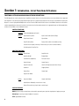
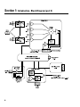
1
CM16a
Amplifier Network Monitor
HARDWARE MANUAL
TD-000086-00
TD-000086-00
Rev. A
¨ WARNING ¨
While QSC has endeavored to develop and produce the most dependable and robust ‘network’ audio product for your use, due to the myriad
of network situations and equipment that may be encountered in its
implementation, QSC cannot be held responsible for network conflicts
and associated consequences that may result. For this reason, QSC
strongly recommends that the network used for implementation of QSControl products be completed separate from all
other networks, data or otherwise. As such, should you elect to
integrate QSControl products with your existing network system, all
risks attendant to such integration of QSControl products with your
existing network or network systems are assumed by you. While QSC
strives to provide the highest quality technical solutions for networked
audio products, in no event will QSC or its suppliers be held liable for
any damages, consequential, incidental or otherwise, including any
claims for lost profits and/or savings resulting from any attempted
integration of QSControl products with your networking systems. No
agent, employee or representative of QSC has any authority to alter or
modify in any manner, the disclosures and recommendations set forth
herein.
© Copyright 2000, QSC Audio Products, Inc.
QSC® is a registered trademark of QSC Audio Products, Inc., Costa Mesa, CA
“QSC” and the QSC logo are registered with the U.S. Patent and Trademark Office
“HyperTerminal” is the copyrighted property of Hilgraeve Inc., Monroe, MI
“Phoenix Contact” is the trademark of Phoenix Contact, Inc., Middletown, PA
“Riacon” is the trademark of RIA electronic, Inc., Eatontown, NJ
“On-Shore Technology” is the trademark of On-Shore Technology, Inc., Tempe, AZ
All other trandemarks are the property of their respective owners
2
TABLE OF CONTENTS: CM16a Amplifier Network Monitor
Section 1: INTRODUCTION
Overview...................................................................................................5
Physical Characteristics & Layout........................................................6
List of Functions & Features...................................................................8
Block Diagram.........................................................................................9
Detailed Description of Functions.......................................................11
Network Description.............................................................................14
Network Examples................................................................................15
Section 2: INSTALLATION
Basics:
Unpacking............................................................17
What is Included.................................................17
Location Considerations....................................17
Mounting the CM16a..........................................17
Connecting:
AC Power..............................................................18
Audio Inputs.........................................................19
Page Input............................................................20
RLY/TRG Input......................................................20
RLY Output............................................................20
Monitor Chain In/Out..........................................20
10BASE-T Input/Output........................................21
RS-232 Port...........................................................21
Amplifiers.............................................................21
Rear Panel Detailed Illustration & Hookup Example........................22
Section 3: OPERATION
General:
Amp Setup, Network Setup...............................24
LED Behavior........................................................25
BYPASS Switch Usage......................................25
Serial Port Interface...........................................27
Telnet Access......................................................30
Fuse Replacement...............................................31
Section 4: SPECIFICATIONS.......................................................................................................................................32
Section 5: ARCHITECT’S & ENGINEER’S SPECIFICATION..................................................................................36
Section 6: APPENDIX
Ethernet Cable & RS-232 Pinouts ........................................................37
DataPort Pinout and “Phoenix”-type Connector Part Numbers......38
Section 7: QSC INFORMATION
How to Contact QSC Audio Products..................................................39
3
EXPLANATION OF GRAPHICAL
SYMBOLS
The lightning flash with arrowhead symbol, within an equilateral triangle, is intended to alert the user to the presence of
uninsulated “dangerous voltage” within
the product’s enclosure that may be of
sufficient magnitude to constitute a risk of
electric shock to humans.
The exclamation point within an equilateral triangle is intended to alert the
users to the presence of important operating and maintenance (servicing) instructions in the literature accompanying the product.
EXPLICATION DES SYMBOLES
GRAPHIQUES
Le symbole éclair avec point de flèche à
l’intrérieur d’un triangle équilatéral est
utilisé pour alerter l’utilisateur de la presence à l’intérieur du coffret de “voltage
dangereux” non isolé d’ampleur suffisante
pour constituer un risque d’elétrocution.
Le point d’exclamation à l’intérieur d’un
triangle équilatéral est employé pour
alerter les utilisateurs de la présence
d’instructions importantes pour le
fonctionnement et l’entretien (service)
dans le livret d’instruction accompagnant
l’appareil.
ERKLÄRUNG DER GRAPHISCHEN
SYMBOLE
Der Blitz nach unten zeigendem Pfeil in
einem gleichseitigen Dreieck weist den
Benutzer auf das Vorhandensein einer
unisolierten, gefährlichen Spannung“ im
“
Gehäuse hin, die stark sein kann, einer
Person einen elektrischen Schlag zu
versetzen.
Das Ausrufzeichen in einem gleichseitigen
Dreieck weist den Benutzer auf wichtige
Betriebs- und Wartungs- vorschriften in
den beiliegenden Unterlagen des Gerätes
hin.
CAUTION
RISK OF ELECTRIC SHOCK
DO NOT OPEN
CAUTION: To reduce the risk of electric shock, do not
remove the cover. No user-serviceable parts inside.
Refer servicing to qualified service personnel.
WARNING: To prevent fire or electric shock, do not
expose this equipment to rain or moisture.
AVIS
RISQUE DE CHOC
ÉLECTRIQUE
NE PAS OUVRIR
ATTENTION: Pour eviter les risques de choc électrique,
ne pas enlever le courvercle. Aucun entretien de pièces
intérieures par l’usager. Confier l’entretien au personnel
qualifié.
AVIS: Pour eviter les risques d’incendie ou d’électrocution,
n’exposez pas cet article à la pluie ou a l’humidité.
VORSICHT
GEFAHR EINES
ELEKTRISCHEN SCHLAGES.
NICHT ÖFFNEN!
VORSICHT: Um das Risiko eines elektrischen Schlages
zu vermindern, Abdeckung nicht entfernen! Keine Benutzer
Wartungsteile im Innern. Wartung nur durch qualifiertes
Wartungspersonal.
WARNUNG: Zur vermeidung von Feuer oder elektrischen
Schlägen, das Gerät nicht mit Regen oder Feuchtigkeit in
Berührung bringen!
SAFEGUARDS
Electrical energy can perform many useful functions.
This unit has been engineered and manufactured to
assure your personal safety. Improper use can result
in potential electrical shock or fire hazards. In order
not to defeat the safeguards, observe the following
instructions for its installation, use and servicing.
PRECAUTIONS
L’énergie électrique peut remplir de nombreuses
fonctions utiles. Cet appariel a été conçu et réalisé
pour assurer une sécurité personnelle entiére. Une
utilisation impropre peut entraîner des risques
d’électrocution ou d’incendie. Dans le but de ne pas
rendre inutiles les mesures de sécurité, bien observer
les instructions suivantes pour l’installation, l’utilisation
et l’entretien de l’appareil.
4
Federal
Communications
Commission (FCC)
Information
NOTE: This equipment has been
tested and found to comply with
the limits for a Class A digital
device, pursuant to Part 15 of the
FCC Rules. These limits are designed to provide reasonable protection against harmful interference in a commercial installation.
This equipment generates, uses,
and can radiate radio frequency
energy and, if not installed and
used in accordance with the instructions, may cause harmful interference to radio communications. Operation of this equipment
in a residential area is likely to
cause harmful interference, in
which case the user will be required to correct the interference
at his or her own expense.
Section 1: Introduction- Overview
The QSC CM16a Amplifier Network Monitor provides powerful
The DataPort connections are made with ordinary VGA computer
amplifier management and zone paging capability in a QSControl
monitor-type cables (HD-15 male-to-male). These cables are
networked audio system using Ethernet networking technology
the same type that are used on personal computer systems to
to communicate with the host computer/system controller.
connect the monitor to the computer. This allows you to use
commonly available cabling for interconnecting amplifiers to the
CM16a. Each DataPort connection supports the control and
From all of us at QSC Audio Products, thank you for your purchase.
monitoring functions for two audio channels. When using the
CM16a with amplifiers that have more than two channels (such
The host computer uses the QSControl application software to
operate the networked audio system, including the CM16a’s and
as the 4 channel cinema amplifiers) additional DataPort connections are required.
their amplifiers. The software operates on the Microsoft Windows NT® version 4.0 operating system and can be customized
using Microsoft® Visual Basic Professional Edition. The network
may theoretically have hundreds of CM16a’s but the real-world
limitation is determined by the network bandwidth, type and
configuration.
This manual is intended to be a reference for installing and
connecting the CM16a as well as outlining the hardware capabilities of the CM16a. The actual operation of the CM16a is dependant upon the instructions received from the control software.
Note that not all hardware features may be supported by the
current software revision. Please refer to the software’s documentation or help file for information regarding software features, usage and functions.
The CM16a is not a “plug-and-play” replacement for the CM16.
The CM16a has a much improved feature-set and height has been
reduced from 2RU to 1RU. Additionally, connectors are slightly
different between the two. Weight has been reduced from 22 to
11 pounds.
A final note; The CM16a is a control and monitoring device that
relies on software to do its job. The functions and capabilities
provided in the design of the CM16a can only be realized with
proper software implementation. Keep in mind that this manual’s
intent is to outline these capabilities and provide a reference for
properly installing and interconnecting the CM16a to the networked system’s host computer, the audio inputs and the amplifiers to be controlled and monitored. A thorough knowledge of the
control software’s features and operation will provide the best
The CM16a performs control and monitoring functions for QSC
possible results for the end user.
amplifiers equipped with a DataPort. This could be up to eight 2channel or four 4-channel amplifiers (or some combination of
these). The amplifiers that are supported by the CM16a are the
PowerLight, PL2, DCA, and CX series of QSC amplifiers that have
Note: In this manual, bold type (e.g. PORT A) within the paragraph text indicates a control or connection that is labeled
similarly on the CM16a.
a built-in Data Port. Models that do not have a built-in DataPort
or models that have a DP-1 option (such as the EX and MXa
series) are NOT supported by the CM16a.
5
Section 1: Introduction- Physical Characteristics & Layout
PHYSICAL CHARACTERISTICS
Each CM16a is one rack space in height (1RU) and has an internal AC power supply. Its chassis depth is 37.7 cm (14.84 in.). The width of
the chassis is 44.0 cm (17.32 in.). For the detailed mounting dimensions, please see specification section. The weight of the CM16a is
approximately 5 kilograms (11 pounds).
FRONT PANEL (numbers correspond to reference locations shown in illustration to right)
The front panel of the CM16a includes:
1- AC OFF / POWER switch
2- Cooling air exhaust vents (intake vents on left side of chassis as viewed from the front)
3- AC POWER indicator LED
4- DIAGNOSTIC indicator LED
5- Network status indicator LED’s ( RCV, XMT and LINK STATUS), duplicated on rear panel for convenience
6- PORT A through PORT H connection indicator LED’s
7- Access hole for the BYPASS switch (this is not labeled on the panel)
REAR PANEL (numbers correspond to reference locations shown in illustration to right)
The rear panel of the CM16a has duplicates of the RCV, XMT and LINK STATUS indicator LED’s so that network status can be detected
from the rear of the unit when installed in the equipment rack. The rear panel provides the following connections:
8- Eight HD-15 receptacles (PORT A through PORT H) for connection to amplifiers with VGA-type cables
9- Sixteen “Phoenix”-type (Euro-style) 3-pin receptacles for audio inputs (PORT A CH 1 through PORT H CH 16)
10- One “Phoenix”-type 5-pin receptacle for audio monitoring functions (MONITOR CHAIN, IN and OUT)
11- One “Phoenix”-type 3-pin receptacle for paging audio signal input (PAGE)
12- One “Phoenix”-type 2-pin receptacle for remote sensing (example: detecting a switch closure or logic event; RLY / TRG IN)
13- One “Phoenix”-type 3-pin receptacle for access to SPDT relay contacts (used for remote switching of external devices; RLY OUT)
14- One RJ-45 type receptacle (10BASE-T Ethernet computer network connection)
15- One DB-9 type receptacle (RS-232 Port for network and firmware utilities)
16- IEC-type detachable AC power cord receptacle (for connection to AC power line) with integral fuse holder
6
Section 1: Introduction- Physical Layout Diagram
7
Section 1: Introduction- List of Functions & Features
FUNCTIONAL LISTING, BLOCK DIAGRAM & DETAILED DESCRIPTIONS
The CM16a performs control and monitoring of amplifiers remotely. Below is a listing of the functions that are available for the supported
QSC amplifiers. The following two pages (Block Diagram part 1 & 2) graphically illustrate the main functions of the CM16a. Following the
diagram is a section giving detailed explanations on each functional block that will aid in the use of the CM16a. Note that not all features
may be supported by the current revision level of software (consult software documentation for supported feature set). Where applicable,
functions are available on each individual channel.
CONTROL FUNCTIONS
Amplifier: Power (Standby/Operate Control)
CM16a:
Input Sensitivity Select
Input Source Select (Normal/Page)
Signal Level Control
Signal Mute
Signal Polarity Select
Paging Control (with customizable routing)
Contact Closure Output (switching of internal relay for control of external device)
Paralleling within DataPort Pair
MONITOR FUNCTIONS
Amplifier: Power Status
Amplifier Gain
Amplifier Model
Bridge Mode
Load Monitor (impedance)
Protection Status
Output Voltage
Output Current
Output Power (real)
Heat Sink Temperature (with Over-Temp.)
Headroom
Clipping Detect
Output Short
Output Open
Output Level Meter
CM16a
Input Level Meter
Output Level Meter
Audio Monitor Module (4 channel mono. mixer)
External Event Sensing (a logic-level or switch input)
SPECIAL FEATURES
DAC (digital-to-analog converter) that can be used for generating test signals & the playback of paging messages
RS-232 Port for setting of network address information
TFTP upgradeable firmware
8
Section 1: Introduction- Block Diagram (part 1)
The following diagrams illustrate the basic functional blocks of the CM16a. Keep in mind that the first diagram is “duplicated” for each of the eight ports.
9
Section 1: Introduction- Block Diagram (part 2)
10
Section 1: Introduction- Detailed Description of Functions
AUDIO FUNCTIONS
AUDIO MONITOR CHAIN FUNCTIONS
Audio Inputs- These are the “Phoenix”-type 3 pin connec-
Pre-Fader Monitor- Monitors the audio path at the point
tors used for balanced line level audio-signal input.
before the Level Control block (i.e. the input to the CM16a).
Input Sensitivity- Sets the sensitivity of the Audio Inputs to
Post-Fader Monitor- Monitors the audio path at the point
either 1 Volt or 3 Volts (r.m.s.). This selection should coincide
after the Level Control, Mute, and Polarity blocks (i.e. the
with the level of the audio signal provided for each channel.
output from the CM16a).
Input Source: Normal/Page- Selects the input source for
Amplifier Monitor- Monitors the audio at the output of the
each channel. Normal input is the audio connected at the
amplifier (i.e. the speaker terminals of the amplifier).
Audio Input terminals. Page input is the audio provided by the
Paging Input Module.
Level Control-
Provides adjustment of the signal level
delivered to the amplifier for each channel. Adjustment is from
-95.5dB to 0dB in 1/2dB steps.
Meter-These points are indicators of where in the audio path
the software can “meter” the audio.
Off- This selection disconnects the monitor for the channel.
Level Adjust- Provides adjustment of the signal level delivered to the Monitor Module from each of the selectable “tap”
points of a channel’s audio path. Adjustment is from -95.5dB
to 0dB in 1/2dB steps.
Monitor Module- This module functions as a four-input
mixer with software selection of the input channels. The four
Mute- Actively mutes the audio signal being passed by a
selected channels are summed with the external input Moni-
channel. No signal is delivered to the amplifier when a channel
tor Chain In. For each of the inputs, the “tap” point is
is muted.
selectable from the pre-, post-, amplifier and off positions.
Parallel Mode- When parallel mode is selected, the input to
the first channel is also applied to the second channel. When
in parallel mode, the input is ALWAYS from the first (or odd
numbered) input. The second (or even numbered) input is
ignored; this includes the PAGE signal. This feature is useful
for sending one input signal to both amplifier channels without
AMPLIFIER CONTROL FUNCTIONS
having to wire jumpers between the two input connectors.
Standby/ Operate- Controls the amplifier’s power status-
Polarity- Determines the polarity of the signal delivered to
ON- amplifier operational
the amplifier for each channel.
STANDBY- amplifier in standby mode
NOTE! The amplifier must be powered in order to respond to
any commands issued by the CM16a
11
Section 1: Introduction- Detailed Description of Functions
AMPLIFIER MONITORING FUNCTIONS
Protect Status Detect- Reports if the amplifier has
Amplifier Model Detect- Identifies what model of
entered “protect” mode (such as thermal, over-current
QSC amplifier is connected to the CM16a’s DataPort.
or power-up muting protect status).
Amplifier Gain Detect- Reports the setting of the
Real Power Detect- Reports the “real” power the
amplifier’s gain setting (in dB) for each channel.
amplifier is delivering. This “real” power is not the
same as “reactive” power.
Bridge Mode Detect- Detects the position of the
bridge mode switch on each amplifier.
Threshold Adjust- This indicates that the behavior of
the associated block requires the input of a threshold
Clip Detect- Detects amplifier clipping on each channel.
Headroom Metering- Reports the “available” re-
value in software that must be crossed for the detection
to occur. This allows the system operator to tailor the
behavior of the system to each application.
maining signal level that the input signal can be driven
before clipping will occur.
PAGING FUNCTIONS
Heat Sink Temperature Metering- Monitors the
heatsink temperature of each channel of each amplifier
Input Sensitivity- Sets the sensitivity of the Page
connected to the CM16a. If the temperature exceeds a
Input to either 1 Vrms or 3 Vrms. This selection should
user specified value (in software) then the Over-Temp.
coincide with the level of the audio signal provided for
“object” will alert the system operator.
the Page Input.
Load Monitor Detect- Monitors the impedance of
DAC- This is a digital-to-analog converter that takes
the load at the amplifier output for each channel.
digital information from the internal microcontroller
and outputs the corresponding analog “equivalent” to
Output Current Meter- Provides for metering of the
amplifier’s output current on each channel.
the appropriate channel PAGE insert points . This occurs only by instructions issued by the system operator
Output Voltage Meter- Provides for metering of the
or a custom control application. It can be used for a
amplifier’s output voltage on each channel.
variety of purposes from the playback of “canned”
Output Open Detect- Detects when the load connected to the amplifier is above a user specified value
in software.
paging messages to testing of the complete system.
Internally, this function is placed within the PAGING
INPUT MODULE as shown in the block diagram. Analog
Page Input is disabled when using the DAC.
Output Short Detect- Detects when the amplifier
load is below a user specified value in software.
Page Input- This is the “Phoenix”-type 3 pin connector used for balanced line level analog page audio-
Power Status Detect- Reports AC power status of
the amplifier (ON/standby/ OFF).
12
signal input.
Section 1: Introduction- Detailed Description of Functions
RS-232 PORT FUNCTIONS
CONTACT CLOSURE I/O FUNCTIONS
RS-232 Port- The RS-232 (serial) port is used to
RLY OUT- This is used for remotely controlling an
electrical device in an on/off manner (such as a cooling
fan, an audible alarm, a light, etc.). An internal SPDT
(single-pole, double throw) relay is controlled by software command. Its contacts are accessible at the rear
panel RLY OUT connector and are labeled:
NC (normally closed)
communicate with the CM16a for Ethernet address
setup purposes and other diagnostic purposes. Most
users will never have a need to access the RS232 port,
but for customized networks and for troubleshooting
system problems, it may be necessary.
For the RS-232 port utilities, see the Operation
section, “Serial Port I/O Interface”. This section
outlines the proper connection and communica-
NO (normally open)
C (common)
tion settings required to communicate with the
RLY/TRG IN- Detects the closure (or opening) of a
CM16a via the serial (RS232) port.
switch connected to the RLY/TRIG IN terminals on the
If the CM16a is connected to an Ethernet network
rear panel. Also accepts CMOS and TTL logic-level
where the factory-provided Ethernet address informa-
inputs. An example is the detection of a limit-switch
tion is not acceptable, a configuration utility must be
that indicates an open door on an equipment cabinet.
run. This involves connecting a computer with a properly configured serial port to the CM16a using a nullmodem type cable (such as a “Laplink” cable) and
running a dumb-terminal program (HyperTerminal is
the Microsoft® Windows- supplied program). DO NOT
CHANGE THE FACTORY SETTINGS UNLESS YOU ARE
CERTAIN OF WHAT YOU ARE DOING! If addressing is
configured incorrectly, the CM16a may not respond to
network control.
13
Section 1: Introduction- Network Description
QSC CM16a Amplifier Network Monitors are designed to operate on standard 10BASE-T Ethernet. Each CM16a operates as a
respective node on its network; each unit contains a programmable IP address in nonvolatile memory and will therefore present no
conflict with any other node on the same network. Ethernet devices such as hubs, repeaters, switches and routers will usually afford
the flexibility to configure the network as needed.
The system controller computer on the network must have an Ethernet-compatible network interface card (NIC) installed.
Additionally, if operation during power outage or interruption is required, an uninterruptable power supply (UPS) will be required for
the host computer , CM16a, and any hubs, switches or repeaters. If the CM16a is disconnected from the network for any reason, it
will continue to process audio using the last settings.
The CM16a connects to the network via its RJ-45 connector on the rear panel. This allows direct connection to a 10BASE-T network.
Use Category 3 (or better) unshielded twisted pair (UTP) Ethernet Cable. Most ready-made Ethernet patch cables available today are
rated at least Category 5 making them suitable for this application.
One side note regarding Ethernet cabling: Although Category 3 data cable is called out as the minimum requirement, it is increasingly
difficult to find. Higher grades of cable are becoming the “normal stock” with the proliferation of 100BASE-T Ethernet. Category 5
Ethernet cable is the most widely available type of data cabling as of this writing. So what does this mean? Use Category 3 if it is
available and cost effective. If the cost of Category 5 cable is not prohibitive, it may be desirable to do your cabling runs with Category
5 due to its increased data rate capabilities. The extra capability may be needed for future system expansion where 100 BASE-T
devices are used. 10BASE-T capability is all that is required for the CM16a and thus the call out for Category 3 as the minimum.
There are three LED indicators on the CM16a that relate to network operation. They are described Section 3: Operation .
14
Section 1: Introduction- Sample Network Topologies
The simplest network configuration is a single
system controller computer and a CM16a connected by a single Ethernet crossover cable. A
standard Ethernet cable would NOT work. The
crossover-type cable must be used when connecting the CM16a directly to the system controller computer. This type of cable switches
(or crosses over) the transmit and receive signals from one end to the other enabling connection without a hub or repeater.
For distances longer than 100 meters (~300
feet) a repeater must be used. An active hub
may be used as well. Active hubs “clean up”
and retransmit the network traffic, much as a
repeater does, only with multiple ports. The
active hub would allow for future expansion.
If there are two or more CM16a’s in
the network (or other network devices present) use a hub to create a
star topology.
15
Section 1: Introduction- Sample Network Topologies
Some networks have multiple system controller computers. This configuration is essentially the same as the second example
with the addition of the second computer
attached to the hub.
To create the more complex distributed star
topologies needed for larger systems, use
additional hubs. Some hubs have special
uplink ports for connecting to other hubs via
a standard Ethernet cable. If the hubs do not
have uplink ports, then the hub-to-hub connection should use a crossover-type Ethernet
cable.
16
Section 2: Installation- Basics and Mounting
UNPACKING
There are no special unpacking precautions for the CM16a. However, it is recommended that you keep the original packing material for reuse
in the rare event that service be required on the CM16a. If service is required and the original packing material is not available, ensure that
the unit is adequately protected for shipment (strong box of appropriate size, sufficient packing material to prevent impact damage or load
shifting).
WHAT IS INCLUDED IN THE CARTON
1- CM16a Amplifier Network Monitor
2- AC Power Cord
3- One complete set of the “Phoenix”-type connectors (18 pcs. of 3-pin style, 1 pc. of 5-pin style & 1 pc. of 2-pin style)
4- Hardware manual (this document)
LOCATION CONSIDERATIONS
Where the CM16a is installed is dependent upon the location of audio input sources, amplifiers and network access. The system controller
computer should be located someplace convenient for the system operator. In most instances, the system controller computer is remote
from the CM16a and the amplifiers . It is preferable to install the CM16a and the amplifiers in the same or adjacent equipment racks; this
allows the cabling between them to be standard VGA monitor cables. These cables are generally 2 meters long (6.5 feet). For longer cabling
runs, contact QSC’s Technical Services Department at (800) 772-2834 (toll free U.S.A. only) or (714) 957-7150. QSC offers a special cable
with individually-shielded twisted-pairs for each audio path; this cable can be used over distances as long as 100 meters (328 feet).
The maximum length of any 10BASE-T Ethernet network segment (cabling between any node and the next node, hub or repeater) is 100
meters (328 feet). The location of hubs and repeaters must be such that this distance limit is not exceeded. If this is impractical or impossible,
then use appropriate network transceivers and fiber optic cabling. For larger Ethernet networks, the use of Ethernet routers may be
necessary.
MOUNTING THE CM16a
The CM16a is secured to the equipment rack with four screws and washers. Be sure to support the weight of the CM16a when securing
to avoid distorting or bending the front panel mounting ears. For mobile, touring or portable applications, support the rear of the CM16a
using the rear mounting tabs provided or contact QSC’s Technical Services Department to order rear rack ear extensions. The rear rack ear
extension kits add flexibility to you installation options as well as a support-pin option that requires one-time hardware installation at the
rear of the rack. For the locating dimensions of the rear support mounting tabs, see the dimensional diagram in the specification section.
17
Section 2: Installation- Mounting and AC Power
MOUNTING THE CM16a (continued): The illustration below shows the basic mounting technique.
The CM16a uses fan-drawn air for cooling. The air intake is on the left side of the chassis and the exhaust vents are on the front panel. Be
certain not to obstruct these openings! Allow ample “open space” around them in order to maintain unobstructed air flow.
Note that the CM16a’s recommended ambient operating temperature is 0°C. to 50°C. (32°F. to 122°F.). Do not install
the CM16a in environments that expose it to temperatures outside this range. Keep in mind that some
equipment rack installation environments can get quite hot. If there is any question, measure the air temperature
inside the equipment rack and supply additional cooling (air flow) to keep the ambient temperature within the
specified limits. QSC amplifiers use back-to-front air flow and therefore do not exhaust hot air into the rack.
CONNECTING AC POWER
The CM16a uses a detachable IEC standard power cord for connecting to a grounded AC
REAR PANEL- POWER CORD RECEPTACLE
source. To connect power to the CM16a: identify the proper end of the cord, match the
orientation of the receptacle on the rear panel and insert firmly into the receptacle. The
power supply will accept from 85 to 264 Volts AC, 47 to 440 Hertz, without any changes. Make
sure that the power cord used is suitable for the line voltage that the CM16a is connected
to. If a different type of IEC power cord is required (different style of plug on the outlet end)
contact QSC’s Technical Services Department to obtain the correct cord assembly.
DO NOT CONNECT THE CM16a TO POWER SOURCES OUTSIDE THE SPECIFIED RANGES OF VOLTAGE OR
FREQUENCY! DAMAGE TO THE UNIT COULD RESULT OR THE USER COULD BE EXPOSED TO UNSAFE
OPERATING CONDITIONS.
18
Section 2: Installation- Connections
CONNECTING AUDIO INPUTS
REAR PANEL- AUDIO INPUTS
The audio inputs are located on the rear
panel. The CM16a uses “Phoenix”-type
(Euro-style) terminal block connectors for
the audio inputs. These connectors allow
the installer to pre-wire the input terminations before the CM16a is installed in the
rack. It also allows for re-routing of audio
inputs by simply interchanging connector
locations without the need for any tools. See Appendix for connector manufacturer’s
part number reference.
BALANCED INPUT CONNECTION
Balanced connection is recommended for all inputs. If unbalanced audio sources are
used, it is preferable to use an appropriate audio transformer (or other unbalancedto-balanced “converter”) to provide a balanced input to the CM16a. If this is not
possible, then it is recommended that the negative terminal and shield terminal be
connected to one another with a jumper wire. The illustrations to the right show the
proper connection of audio program input sources for both balanced and unbalanced
inputs.
UNBALANCED INPUT CONNECTION
The recommended stripping length for the wires is approximately 6 to 8 mm ( 1/4 to
5/16 inch). When stripping the audio cable, be careful not to nick or cut the conductor
strands. After each conductor has been stripped and dressed, insert it fully into the
connector and tighten the retaining screw. When stranded wire is used, carefully
twist the conductor strands together so that when they are inserted into the
connector assembly, no loose strands short adjacent terminals.
STRAIN RELIEF
For heavy-duty input cables, the use of connectors with integral strain relief
is recommended. These connectors have a large plastic tab molded as part
of the assembly which provides an area to tape or tie-wrap the cable to. At
the time of this writing, only the 3-terminal with the strain relief was
available through QSC . See Section 6 (Appendix) for connector part
numbers.
19
Section 2: Installation- Connections
CONNECTING PAGE INPUT
The PAGE input is identical to the AUDIO INPUT connections.
REAR PANEL- PAGE, RELAY & MONITOR CONNECTIONS
Please refer to the previous page for connection guidelines.
CONNECTING THE RLY/TRG IN
The RLY/TRG IN connector is a two-pin version of the
“Phoenix”-type connector. When using this input for a switchclosure (or opening) event, the two terminals should be
connected to the switch contacts directly. This type of event
detection can be used with relay contacts as well. If used
with a logic-type device, the low-end of the logic connection
should be connected to the minus (–) terminal and the activeend should be connected to the plus (+) terminal. This input
is compatible with TTL & CMOS logic family devices. For the
defined limits of input to this connector , please refer to the
specification section.
CONNECTING THE RLY OUT
The RLY OUT connector provides access to the internal relay’s
contacts for remotely controlling an external low voltage device or
circuit. This internal relay is rated for 70V (DC or ACrms), 250 mA
(switched) and is isolated from ground. There is one common
terminal, one normally-closed contact terminal and one normallyopen contact terminal. These are labeled as C, NC and NO on the rear
panel. When the relay is not energized, the C terminal is connected to
the NC terminal and the NO terminal is not connected; when the relay
is energized the C to NC connection is opened and the C to NO
connection is closed.
CONNECTING THE MONITOR CHAIN IN/
OUT
The MONITOR CHAIN connector is a five pin version
of the “Phoenix”-type connector. The center pin is the
shield connection for both the input and output of the
monitor chain. Note also that the positive terminal of
the input and output connections are on the outer pins
of this connector.
.
DO NOT CONNECT VOLTAGES EXCEEDING 70 VOLTS (DC or AC rms) TO THE RLY OUT CONNECTOR! DAMAGE TO THE CM16a COULD
RESULT OR CREATE HAZARDOUS OPERATING CONDITIONS!
20
Section 2: Installation- Connections
CONNECTION TO 10BASE-T (network connection)
Connection to the Ethernet network is made using the RJ-45 type
connector labeled 10BASE-T on the rear panel. The RJ-45 is the standard
network connector for Ethernet networks. Insert the RJ-45 plug into the
receptacle with the lock-tab oriented toward the bottom of the CM16a
and push firmly until the connector locks into place (usually an audible
“click” can be heard). Refer to Section 1 of this manual for Ethernet
connection schemes and cabling. Keep in mind that if the CM16a is
connected directly to the system controller computer’s network interface
card, a crossover type cable is required. All other connection methods
utilize normal Ethernet cabling.
CONNECTING TO THE RS-232 PORT
The RS-232 port can be used for setting various operational parameters that are CRITICAL to proper operation of the CM16a. The network
address settings can be changed through this port BUT SHOULD NOT BE CHANGED UNLESS YOU KNOW FOR CERTAIN WHAT YOU ARE
DOING! Connection is made with a null-modem serial cable with a DB-9 male plug to the CM16a. Refer to Section 3 for more information.
CONNECTING TO AMPLIFIERS
Amplifiers are connected to the CM16a via the PORT connections on the rear panel. These HD-15 type connectors are labeled PORT A
through PORT H. The connection itself is made using standard VGA monitor cables (the same type of cable that interconnects personal
computers to their monitors). To connect the cables to the CM16a, simply orient the HD-15 connector with its wider-side down (look at the
connector, one side of the plug’s metal surrounding is wider than the other) and align it with the receptacle, then gently push into the
receptacle until it is firmly seated. Use the retaining screws (or finger-screws) supplied on the cable ends to secure the plug to the CM16a.
Be sure to tighten “finger tight” to avoid damage to the HD-15 receptacle.
When connecting to 4-channel amplifiers, two basic rules must be adhered to. First, both DataPorts of the amplifier must be used.
Second, both must be connected to the same CM16a. If only one DataPort connection is used, the CM16a will not control or monitor
the amplifier correctly ( the same applies for connecting the two amplifier DataPorts to two separate CM16a’s; the system will not function
properly). Insure that both amplifier DataPorts are used and that they are connected to the same CM16a. You do not have to use adjacent
ports on the CM16a (i.e. PORT C and PORT D). You can use any two ports for convenience; the only impact of doing this is that the System
Manager software control panel will not show all four channels next to each other.
For 2-channel amplifiers, it is a simple one DataPort, one cable connection to the appropriate rear panel PORT receptacle on the CM16a.
21
Section 2: Installation- Rear Panel Detail
22
Section 2: Installation- Hookup Example
23
Section 3: Operation- General
AMPLIFIER SETUP- The amplifiers connected to the CM16a should have their power switches in the ON position and their gain
controls set as required by the user (seeInitial Testing note below).
NOTE! For initial testing, it is advisable that the amplifiers be set for the lowest useful gain (volume)
setting until it is verified that the system is operating as expected. After the system setup has been
verified and tested, gain settings may be set as required
NETWORK- The network should be operable and QSControl software should be installed/running on the system controller computer.
CM16a OPERATION- Turn the Power ON!
Operation of the CM16a is accomplished with QSControl software. The only operation required on the CM16a itself is flipping the power
switch from the OFF position to the POWER (ON) position. It is important to understand the start-up behavior outlined below.
When first taken out the box, the CM16a will power up in a muted state with all faders at -95.5 dB., polarity set to normal, sensitivity
set to 3V, and any amplifiers connected to the CM16a will be in STANDBY mode. This “setup” is the factory setting for Preset #0. The CM16a
has 16 presets for quickly recalling settings. They are numbered 0 (zero) through 15. These presets are useful for quickly changing from one
setup to another without having to change each individual control to a new setting. An example might be in a house of worship where the
audio system setup is different for each service. Instead of having to keep a trained system operator on location, another individual with
minimal training can be shown how to change to the desired preset for each situation.
The presets are useful tools, but Preset #0 acts differently than the others. Each time the CM16a is powered up, it recalls its settings from
Preset #0. The factory Preset #0, discussed above, is a muted state with amps in STANDBY mode. When setting up your own presets, they
should be stored in Preset #1 through Preset #15. The reason for not actively using Preset #0 is as follows: Let’s say you’re operating
your system in Preset #12 and you change the setting of one fader. The new setup is NOT the same as Preset #12, so the CM16a starts
a 4 minute timer from the time the control was changed. After the 4 minutes has elapsed with no further control changes,
it saves the NEW scene into Preset #0 . Preset #12 is left unchanged. Whatever was in Preset #0 is now gone forever. This insures
that the next time the CM16a is powered up, it’s settings are the same as you left them. Remember, the CM16a always powers up
in Preset #0. Refer to the software documentation for further information.
Preset #0 will only be overwritten 4 minutes after the last control change. This includes if the CM16a is placed into one of its BYPASS
modes as discussed in the following section. If the CM16a is placed into BYPASS mode and operated for at least 4 minutes without control
changes, then the BYPASS mode is saved in Preset #0. The next time the CM16a is powered up, it will start up in Preset #0 (or BYPASS
in this case). This could cause dangerously high output levels from the system. Insure amplifier gain controls are reduced to
safe levels ANY time BYPASS mode is used.
The CM16a has all outputs momentarily muted at power-up to prevent unexpected audio pops, clicks or thumps. Remember: At power up,
the CM16a will always start operating with the settings saved in Preset #0. Once network communication has been established between
the host computer and the CM16a, the CM16a may be controlled remotely . In the event that the network communications link is
lost while the CM16a is operating, it will continue to operate with its last settings intact.
24
Section 3: Operation- LED Behavior & Bypass Switch Usage
LED BEHAVIOR- When the power is switched ON, all of the LED’s light briefly and then the PORT LED’s sequence through two patterns.
The LED’s then resume normal operation. The LED functions are described below.
POWER LED- The power LED will illuminate whenever the power switch is in the POWER (ON) position.
DIAGNOSTIC LED- This indicator first illuminates during the power-on self test of the CM16a, then should turn off. It will also illuminate
to indicate that the CM16a self-test has detected an unexpected event, such as a corrupted firmware update via TFTP or a memory boot
failure. This would typically be accompanied by a “fault code” displayed by the PORT CONNECTED indicators (described below). If the
DIAGNOSTIC LED remains illuminated, try resetting the CM16a by cycling power off and on once. Should the indication persist, contact
Technical Services for guidance.
NETWORK STATUS LED’s- For diagnostic purposes, there are three network status LED’s on the front and rear panels of the CM16a.
They are labeled RCV, XMT and LINK STATUS. Their locations are shown in the illustration at the start of the Introduction section. Their
functions are described below.
RCV- This LED lights up any time the CM16a receives data over the network.
XMT- This LED lights up whenever the CM16a transmits data over the network.
LINK STATUS- When lit, this LED indicates that the CM16a is connected to an operating Ethernet network.
If not lit, there is most likely a cabling problem between the CM16a and the hub or possibly a fault in the hub.
PORT CONNECTED LED’s- These LED’s are labeled PORT A through PORT H on the front panel. The respective LED will illuminate
when functional connection has been made between the CM16a and an amplifier. The amplifier’s power does not have to be ON in order
for the LED to indicate successful connection. As mentioned above, these LED’s may also display specific “fault codes” if the CM16a detects
an internal failure in one of its associated self-test/diagnostic parameters. The “fault code” will be in the form of a specific sequence of
these LED’s being illuminated.
BYPASS SWITCH USE
There are two distinctly different BYPASS modes.
The first mode is the “Oops, I forgot the computer” or system troubleshooting type of BYPASS. If you are unable to communicate with
the CM16a for any reason and you need to bypass the unit, it can be done with the push of a button instead of rewiring the system.
If the CM16a is powered-up and there is no host computer control (or the network is non-operational), the operational state (as saved in
Preset #0, the start-up preset) could prevent the audio from being supplied to the amplifiers. We have addressed this potentially disastrous
situation by providing a BYPASS (or “virtual-wire”) mode switch. The function of this switch is to put the CM16a into a known state of
operation. This “BYPASS” state routes all audio through the CM16a in a “virtual wire” mode (1Vrms input sensitivity, PAGE input
disabled, MUTE disabled, 0 dB level, normal polarity). This insures that audio can still be passed through the CM16a regardless of
network/computer issues.
(continued on next page)
25
Section 3: Operation- Bypass Switch Usage (continued)
NOTE! Before depressing the BYPASS switch, the gain (volume) settings on all amplifiers
connected to the CM16a should be reduced to a safe level. This is advisable because the
CM16a’s “Level Control” will be reset to 0 dB. (or NO attenuation) with the BYPASS. It is
possible that the amplifiers could be at maximum output level if the amplifier gain controls are
not turned down.
Location of BYPASS switch: The front panel has a small access hole on the right side about 12mm (1/2 inch) to the right from the PORT
H LED. It is NOT LABELED to help prevent accidental use. This is the BYPASS mode switch. To return to normal operation, simply reestablish
computer communications via the network or RS-232 and change the appropriate settings (or recall a previously saved Preset).
The way to put the CM16a into this first BYPASS mode (“virtual-wire
mode”) is:
1- Turn the CM16a on and wait 5 to 10 seconds for the start-up LED
sequence to finish.
2- Depress the BYPASS switch (use a paperclip or similar item) and keep
it depressed for at least 5 seconds.
3- The two steps above must be completed within 60 seconds from
power-up. If you miss the timing, just power-down and power-up again and
FRONT PANEL- BYPASS SWITCH LOCATION
repeat steps 1 & 2.
The second mode (“safe” mode)is used if the CM16a becomes inoperable (or behaves in completely unexpected ways) after
uploading a new application file (TFTP file transfer).
If the CM16a behaves in unexpected ways or is not responding to any communications after a new application file is uploaded to it, then
it is likely that the new application file was corrupted during or after the data transfer. If sent a corrupted application file, the CM16a will
not accept this file. The LED’s might even act in unexpected ways. If this occurs, there is a “backup” file in the CM16a that will enable you
to communicate with it.
The way to put the CM16a into this second BYPASS mode (“safe mode”) is:
1- Turn off the power to the CM16a using the front panel power switch.
2- Depress the BYPASS switch (use a paperclip or similar item) and keep it depressed while turning the power on again.
3- The CM16a is now in “safe mode”.
You will now be able to re-establish communications with the CM16a using the RS-232 Input/Output port or the Telnet program in Windows
NT. The following section describes the RS-232 and Telnet features. Once communications has been re-established, the file transfer can
be tried again or the old application file used until the source of the data transfer problem can be found.
26
Section 3: Operation- Serial Port I/O Interface
The RS-232 connector on the rear panel is used as a serial port input/output (I/O). This I/O port is used for accessing controls for the IP address
settings, system “health” data, firmware version information and other related data.
Typically, this interface is not used by the majority of users. But should any system problems arise, the data that may be accessed through
this interface can help to track down the problem. The most common items that might be used are “Display Network Settings” and “Enter
Network Setup”. The remaining selections would typically be used for troubleshooting purposes along with a QSC technical representative
prompting you to access particular menu items so that the data can be interpreted.
The basic setup involves connecting a null-modem type serial cable (or a regular serial cable WITH a null-modem adapter) between your
computer’s serial port and the RS-232 port of the CM16a. Once properly connected, a “dumb-terminal” program (such as Hyper Terminal,
a widely used version on most Windows-based PC’s) is started up and communication established between the PC and the CM16a.
Below is the basic procedure for starting up Hyper Terminal, naming the connection, specifying the communications settings and an example
of “what you should see” for a text-menu once the communications link has been established. As many different systems and configurations
exist on user’s PC’s, the exact appearance of the screen shots may vary from those shown. Furthermore, if programs other than Hyper
Terminal are used, you will need to follow your software’s instructions for establishing communications through your PC’s COM (serial) port.
1) Connect the RS-232 port of the CM16a to an unused serial port (COM port) of a PC using a null modem type cable. These cables are
different than the ordinary serial cable.
2) Open the HyperTerminal program. This program is usually started by clicking the Windows START icon, highlighting PROGRAMS, then
ACCESSORIES and finally, highlighting the Hyper Terminal folder and clicking on its icon.
The screen-shot below shows a typical icon-view of the Hyper Terminal folder (icons shown for each program in the folder). If your system
was setup for a list-view, then you will instead see a list of what’s in the folder. Identify the Hyper Terminal program icon (or name from
the list) and click (or double-click as required) to start the program. In the screen-shot below, the Hyper Terminal icon is the fifth from the
left in the row of icons.
HyperTerminal Icon
27
Section 3: Operation- Serial Port I/O Interface
3) After starting Hyper Terminal, a Connection Description window will
pop-up. It will require that you name your connection.Enter a name for your
new connection (example: CM16a) and click OK to continue.
4) Next, Hyper Terminal needs to know how to “talk” to the CM16a. This
selection depends on which port on your PC the null-modem cable is
connected.
Ignore the first three entry fields (phone number information) and go directly
to the “Connect using:” entry field and click on the down arrow for the dropdown menu selection.
Select the appropriate port (COM1 is used in this example) and click OK
continue. The Properties window should appear next.
5) The Properties window for the selected COM port should now be active.
It should be similar in appearance as the example to the right.
For the Port Settings, use the following information so that communication between the CM16a and the computer is in the same “language”.
Bits per Second
9600
Data Bits
8
Parity
none
Stop Bits
1
Flow Control
Xon/Xoff
Once you have set the properties as outlined, click OK to continue.
If all the connections and communications settings are correct, the main
Hyper Terminal window will appear next (see next page).
28
Section 3: Operation- Serial Port I/O Interface
6) The Hyper Terminal main window will appear next, but blank. Type the letter “h” (for help) and then the “Enter” key. This will prompt
the CM16a to post its menu text. The “h” key is the Help prompt for the CM16a.
7) The next screen will look similar to the Hyper Terminal window above. After typing “h” and “Enter”, a text menu will appear. The menu
should appear very similar to the example above. This is sent by the CM16a and will detail your options and instructions for changing the
address information. Any changes in menu text from the above example might occur after any firmware updates of the CM16a.
From this “main-menu” you will need to make your menu choices and follow the instructions in the following sub-menus or screens. Although
many of the instructions and tests may not pertain to a specific setup or troubleshooting situation, you may be asked to run certain tests
by a QSC technical representative. The results of these tests will help to troubleshoot any problems.
The most common user item that might require settings to be changed would be the IP address information. This would be useful if the IP
address were somehow changed to an unrecognized address and subsequently you were unable to “talk” to the CM16a over the network.
This situation would require the “Display Network Settings” and “Enter Network Setup” items to be accessed and your re-assigning a “good”
IP address.
IP ADDRESS ASSIGNMENTONLY REQUIRED FOR ATTACHING TO EXISTING NETWORKS!
DO NOT CHANGE THE COMMUNICATIONS SETTINGS OF THE CM16a UNLESS CERTAIN OF YOUR ACTIONS. ALWAYS
WRITE DOWN WHAT YOU CHANGED SHOULD YOU NEED TO RETURN TO THE INITIAL SETTINGS.
29
Section 3: Operation- Telnet Access
The features outlined for the RS-232 port can also be accessed via the Ethernet network connection. This feature can save a trip out to the
remote CM16a with a laptop computer as long as the network and software are fully operable.
The Telnet “session” is a standard Windows program. Consult Windows documentation for information reagrding the specifics of Telnet.
It is a very straight-forward program to start and use.
This is the basic procedure for opening a Telnet session:
1- To open the Telnet program. Click START, select RUN, type TELNET in the text
box & click OK.The blank Telnet screen should look similar to the example to the
right.
2- Click on the “Connect” menu header; the drop down menu items will appear.
Choose the “Remote System” option.
3- The “Connect” window then opens. You will need to enter the IP address of the
CM16a that you want to communicate with. Determine the IP address of the
specific CM16a and enter it in the Host Name: field ( the numbers in the screenshot to the right are EXAMPLE ONLY!). Enter the address in four numeric groups
seperated by periods. (NOTE: Port: & Term Type: settings must be as shown)
4- Click on the “Connect” button. If the address entered was correct and network
communications with the CM16a are successful, the Telnet session should open
as shown below. The IP address number that appears at the top of the window will
be different than shown; it will match the IP address that you entered for the
CM16a that you are communicating with.
5- Now you have the same options that are available in the Serial Port I/O (RS-232)
interface section (see pages 25-27).
30
Section 3: Operation- Fuse Replacement
FUSE REPLACEMENT
If the CM16a does not power-up when the POWER switch is in the “on” position (POWER indicator LED does not illuminate) check the
source of AC power and the connection of the power cord at the outlet and IEC receptacle ends. If the AC source is “on” and the power cord
is connected and in good condition, then the condition of the fuses should be checked.
The fuse holder is an integral part of the IEC connector. It contains two fuses.
• To replace a fuse, first detach the AC power cord from the CM16a.
• Then use a flat-blade screwdriver to pry the fuseholder out, as shown at left.
The fuses are held in the round openings in the end of the fuseholder as shown at
left, below. Replace one or both fuses with the same type: 20 × 5 mm, 2 amp, 250V.
A visual inspection of the fuse will usually indicate if the fuse has been “blown”
or not. This method is not foolproof, however, as sometimes the fuse element is
severed close to the end-cap making it impossible to see the break. When in doubt,
test the fuse with an ohmmeter or just replace the fuse. Below is an illustration of a typical clear
glass-cartridge fuse. The “GOOD” fuse has an intact element from end to end and the “BAD” (or
blown) fuse has a break in the element.
If the CM16a continues to “blow” fuses, DO NOT INCREASE THE FUSE RATING as severe
damage to the CM16a could result. Contact QSC for service if fuses repeatedly blow.
If fuse replacement does not enable the CM16a to power up, double-check the AC power source
and the cord assembly before returning the unit for possible repair.
31
Section 4: Specifications- Dimensions
Below are shown the dimensions s of interest for the CM16a. These dimensions are helpful for locating the rear-supports for the CM16a
when used in portable or touring installations. This drawing is NOT to scale!
32
Section 4: Specifications
Input Signal Processing
Frequency response
20 Hz–20 kHz ±0.5 dB
10 Hz–80 kHz ±3 dB
Distortion
<0.01% THD+N @ +4 dBu out
(page input <0.03%)
Dynamic range
>110 dB unweighted
20 Hz–20 kHz
(page input >100 dB)
Polarity
In-phase or inverted
Level control range
-95.5 to 0 dB in 0.5 dB steps
Precision attenuator
transients (“zipper”
noise)
better than 112 dB below
maximum output
Mute
>90 dB attenuation
Inputs
Program inputs
Paging inputs
Monitor bus input
Connector type
16
1
1
“Phoenix-style” (a.k.a.
“Euro-style”) detachable
terminal blocks
Common-mode rejection
Typical, >50 dB, 20 Hz–20 kHz
Worst Case, >40 dB at 20 kHz
Crosstalk (interchannel within
Data Port pair)
>75 dB separation, 20 Hz–20 kHz
Crosstalk (intrachannel, between
Data Port pairs)
>85 dB separation,
20 Hz–20 kHz
measured with all inputs and
outputs terminated
Outputs
Program outputs
Connector type
Pinout
Cable type
Qualified length
Monitor output
Connector
16 (via HD-15)
8 HD-15 data port connections
Special, see appendix
VGA monitor cable
2 meters
1
“Phoenix-style” (a.k.a.
“Euro-style”) detachable
terminal blocks
Type
Grounding
Electronically balanced
All shield terminals connected to
chassis
Type
Grounding
Electronically balanced
Shield terminal connected to
chassis
Nominal level
Maximum level
Impedance
1V/3V rms selectable
+21 dBu
10 kOhm balanced
Nominal level
Maximum level
Output impedance
Output load
+4 dBu
+21 dBu
75 Ohms balanced
600 Ohms minimum
Power amplifier output processing
Power amplifier output monitoring
Output short detect*
Senses load <1 Ohm for Stereo/
Parallel modes; <2 Ohms in Bridged Mono mode
Threshold is adjustable in software
Output open detect*
Senses load >60 Ohms
Threshold is adjustable in software
Output voltage meter
Range automatically matches to
amplifier model used
Output current meter
Range automatically matches to
amplifier model used
*Signal level must be greater than -32 dB, referenced to maximum output of amplifier
33
Section 4: Specifications
Power amplifier management
Power amplifier interface
Compatibility
QSC Data Port equipped amplifiers
Connector and cable
HD-15 VGA cable, 2 meters length
qualified (for longer runs, contact
QSC’s Technical Services Department)
Amplifiers
Protect indicator
Temperature meter
Senses amplifier protect status
Reports amplifier operating
temperature
Software adjustable threshold
Over-Temp. Alert
AC power control
AC mode control
Switches amplifier between
normal and standby mode
Up to eight 2-Ch. amplifiers or four 4-Ch.
amplifiers ( or some combination thereof)
Amplifier status monitor
Clip indicator
Senses channel clipping
AC power indicator
Indicates operate, standby, or
power-down mode
Control room foldback monitoring
Signal monitoring buses
(per CM16)
1
Number of Channels
4
Internal signal tap points
Pre-fader input signal
Post-fader input signal
Power amplifier output
16
16
16
Monitor input
Nominal level
Maximum level
Input impedance
Configuration
Common-mode rejection
Mixed with tap point signal at
unity gain
+4 dBu
+21 dBu
10 kOhm balanced
Electronically balanced, shield
connected to chassis
Typical, >50 dB, 20 Hz - 20 kHz
Worst case, >40 dB, 20 Hz-20kHz
Output
Sum of Monitor input and
signal from internal monitor
tap point
Frequency response
Distortion
Noise floor
Nominal level
Maximum level
Output impedance
Output load
Configuration
25 Hz–20 kHz ±0.5 dB
<0.05% THD @ +4 dBu out
-90.5 dB
+4 dBu
+21 dBu
75 Ohms balanced
600 Ohms minimum
Active balanced
Level
Adjusts amplitude of signal from
tap point
Monitor in to monitor out
Control range
0 dB, ±0.5 dB
-95.5 to 0 dB in 0.5 dB steps
Contact closure inputs and outputs
Inputs
1 discrete input
Configuration
Single-ended input
Resistance for closure detect <1kOhm max
Resistance for open detect >5 kOhm min
Input Voltage Limit
7.000 VDC maximum
“-” input terminal connected to chassis
34
Output
Configuration
1 discrete output
Electromechanical relay, dry
contacts, floating, C, NC, NO
Steady-state current (max.) 0.5 A
Switched current (max.)
0.25 A
Ground isolation
70 volts maximum
Connector
“Phoenix-style” (a.k.a.“Euro-style”)
detachable terminal block connectors
Section 4: Specifications
Network Interface
Physical network
Raw data rate
Frame format
Connector
Ethernet type
Cable type
Max cable length
Grounding
Ethernet, IEEE 802.3 compliant
10 megabits per second
D.I.X. (Ethernet)
RJ-45 female
10BASE-T
CAT-3 (or better) twisted pair
100 m to hub
Floating
Transport network
Internetwork protocol
Transport protocol
TCP/IP
IP
UDP
Application protocol
Version
Revision
QSC24
1
7
RS232 Port
Cable Type
Null-Modem (such as “Laplink”)
Port Settings
Bits per Second
Data Bits
Parity
Stop Bits
Flow Control
9600
8
none
1
Xon/Xoff
General
Physical
Height
Width
Depth
1.72” (1 RU)
19” (standard rack mount)
14.84” (37.7 cm), including
rear supports
AC Power
Voltage
Current
100–240 VAC
1.1 A RMS (@ 100V)
1 A RMS (@ 120V)
0.5 A RMS (@ 230V)
Weight
Mounting
11 lbs (5 kg)
Rear support recommended for
portable or mobile use
Frequency
Disconnect
47– 440 Hz
Detachable power cord with IEC
connector
Operating temperature
0 to 50° Celsius
Fuses
2 Ampere, 250 Volt Rating
5mm diameter, 20 mm length
35
SECTION 5: ARCHITECT’S AND ENGINEER’S SPECIFICATIONS
The Amplifier Network Monitor shall provide input, output,
and status control for DataPort equipped QSC power ampli-
channel monitor signals. A monitor gain control
fiers in an Ethernet-TCP/IP based network audio system.
shall be provided for each monitor tap point to
Sixteen independent channels shall be provided, grouped in
adjust the individual levels of the channel monitor
pairs.
signals prior to their being mixed with the monitor
Amplifier Input Control and Monitoring—For each of the
input signal.
sixteen power amplifier input signals, the CM16a
Contact Closure I/O—The Amplifier Network Monitor shall
shall provide level, mute and polarity control, pre and
provide a trigger contact-closure sense input which
post fade signal level metering and audio monitoring,
shall also be CMOS & TTL signal compatible, and
and selectable 1Vrms or 3Vrms input sensitivity. The
one dry-contact floating SPDT relay output.
Amplifier Network Monitor shall provide a page
input, separate from the normal program inputs,
whose signal may preempt the program signal of any
or all of the sixteen program channels. This input shall
have selectable 1V or 3V sensitivity.
Data Network—All Amplifier Network Monitor functions
shall be controlled and monitored via a 10BASE-T
Ethernet digital control network using the IP transport protocol and the QSControl monitoring application protocol. Rear-panel connection shall be
Amplifier Output Monitoring—For each of the sixteen
provided for 10BASE-T Ethernet. Other than the AC
power amplifier outputs, the Amplifier Network
power switch, the Amplifier Network Monitor shall
Monitor shall provide clipping detection, short and
have no manual controls.
open circuit detection, voltage and current metering, and audio monitoring of the voltage signal.
Amplifier Interface—The Amplifier Netrwork Monitor’s
interface to each power amplifier Data Port shall be
Amplifier Management—For each of the eight DataPort
via an HD-15 connector. The amplifier interface
connections, the Amplifier Network Monitor shall
shall use a standard personal computer Video Graph-
provide AC standby/operate mode control, AC
ics Adapter (VGA) CRT monitor cable. This interface
power state indication, temperature metering, load
shall transmit two amplifier input audio signals as
status, and protect status detection.
well as all control and monitoring signals. Special
Audio Monitoring Chain—For each of the sixteen program channels, the Amplifier Network Monitor
shall provide three monitor points as follows: (1)
be used in this interface to ensure negligible levels
of noise and crosstalk.
pre-fader control, (2) post-fader control, or (3) power
General—All audio inputs and outputs shall be balanced
amplifier output. A channel’s monitor output may
with a nominal input level of +4 dBu and maximum
be selected from one of these three signals, or it
level of +21 dBu. Input connectors shall be of the
may be switched off. The signal at the Amplifier
“Phoenix” detachable terminal strip type.
Network Monitor’s monitor output connector shall
be the sum of the signal at its monitor input connector and four selected (cont’d. next column-->)
36
signal conditioning and grounding techniques shall
The Amplifier Network Monitor shall be the QSC CM16a.
Section 6: Appendix- Ethernet Cable Pinouts
ETHERNET CABLING
This diagram shows the pinout for standard unshielded twisted-pair (UTP) network cable. Both ends of the cable are wired
identically.
RJ-45 pinout for standard Ethernet
patch cable (both ends identical)
A crossover cable has the RX and TX wire pairs switched around at one end. There are only two likely situations that would require a
crossover cable: to connect a single system controller computer directly to a single CM16a device; and to cascade hubs that don’t have uplink
ports.
RJ-45 pinout for an Ethernet
crossover cable
RS-232 Null Modem Cable Pinout
37
Section 6: Appendix- DataPort Pin-out & Connector P-N’s
DATA PORT PINOUT: The diagram to the right shows the pin assignments
used for the HD-15 connectors on the CM16a and amplifier.
NOTE! This information is shown for reference only and is subject to change without
notice as the DataPort feature is specific to QSC products and not intended for interface
to other manufacturer’s equipment.
Pin Signal Description
1
Audio to channel 1 (+)
2
Standby control
3
4
5
6
7
8
9
10
11
12
13
14
15
VMON channel 1 plus encode 1
IMON channel 1 plus encode 2
Clip/protect channel 1
Hard ground
Audio to channel 1 (ground)
Audio to channel 2 (ground)
unused for CM16a, +15V on certain amp’s
Amp reference ground
Audio to channel 2 (+)
Amp IDR (model ID)
VMON channel 2 plus encode 3
IMON channel 2 plus encode 4
Clip/protect channel 2
Description Encode Signals
encode 1
Bridge mode & power detect
encode 2
Temperature, channel 1
encode 3
encode 4
Standby mode detect
Temperature, channel 2
RS-232 PINOUT: The diagram below shows the pin assignments for RS-232.
Pin
1
2
3
4
5
6
7
8
9
Signal Description
DCD
RX
TX
DTR
Signal GND
DSR
RTS
CTS
not used
TERMINAL BLOCK CONNECTOR PART NUMBER REFERENCE- The following manufacturers and part numbers are provided as a
reference to users. The information here is subject to change without the knowledge of QSC.
2 pin: Phoenix Contact - 17 57 01 9; Riacon - 31249102-6; On-Shore Tech - EDZ950/2
3 pin: Phoenix Contact - 17 57 02 2; Riacon - 31249103-6; On-Shore Tech - EDZ950/3
5 pin: Phoenix Contact - 17 57 04 8; Riacon - 31249105-6; On-Shore Tech - EDZ950/5
Strain Relief 3 pin: Phoenix Contact 17 76 16 8
Strain Relief 5 pin: Phoenix Contact 17 76 14 2
WEBSITE reference-
38
Phoenix- phoenixcon.com
Riacon- riaelectronic.com
On-Shore- on-shore.com
Section 7: How to Contact QSC Audio Products
ADDRESS:
QSC Audio Products, Inc.
1675 MacArthur Boulevard
Costa Mesa, CA 92626-1468 USA
TELEPHONE NUMBERS:
Main Number
(714) 754-6175
Sales Direct Line
(714) 957-7100
Sales & Marketing
(800) 854-4079 toll free in U.S.A. only
Technical Services
(714) 957-7150
(800) 772-2834 toll free in U.S.A. only
FACSIMILE (FAX) NUMBERS:
Sales & Marketing FAX
(714) 754-6174
Technical Services FAX
(714) 754-6173
WORLD WIDE WEB:
http://www.qscaudio.com
39
1675 MacArthur Boulevard
Costa Mesa, California 92626 USA
PH: (714) 754-6175 FAX: (714) 754-6174
“QSC” and the QSC logo are registered with the U.S. Patent and Trademark Office