1
DL3800E
Inverse Multiplexer
User’s Guide
Part 098-30380-01 Rev F
July 9, 2001
COPYRIGHT AND TRADEMARKS
Copyright © 2001, Quick Eagle Networks
World copyright reserved. No part of this publication may be stored in a
retrieval system, transmitted, or reproduced in any way, including but not
limited to photocopy, photograph, magnetic, chemical, or other record,
without the prior agreement and written permission of Quick Eagle
Networks.
PRODUCT LIMITED WARRANTY
Quick Eagle Networks warrants to buyer that any unit shipped to buyer,
under normal and proper use, will be free of defects in material and
workmanship for a period of twenty-four (24) months from the date of
shipment to buyer. This limited warranty is void if there is any
unauthorized modification or repair of a unit by anyone other than Quick
Eagle Networks or its authorized agent.
THE FOREGOING WARRANTY IS EXCLUSIVE AND IN LIEU OF ALL
OTHER WARRANTIES. EXCEPT AS OTHERWISE PROVIDED HEREIN,
QUICK EAGLE NETWORKS DISCLAIMS ALL OTHER WARRANTIES,
EXPRESSED OR IMPLIED, INCLUDING, BUT NOT LIMITED TO,
IMPLIED WARRANTIES OF MERCHANTABILITY AND FITNESS FOR A
PARTICULAR PURPOSE. Some jurisdictions may not allow the exclusion
of implied warranties, so some of the above exclusion may not apply to
you.
For further information about warranty and service on your Quick Eagle
Networks product, visit our Web site at www.quickeagle.com.
REMEDIES AND LIMITATIONS OF LIABILITY
All claims for breach of the foregoing warranty shall be deemed waived
unless notice of such claim is received by Quick Eagle Networks during the
applicable warranty period and unless the items claimed to be defective are
returned to Quick Eagle Networks within thirty (30) days after such claim.
Failure of Quick Eagle Networks to receive written notice within the
specific period shall constitute a waiver by buyer of any such claim
irrespective of whether the facts giving rise to such a claim shall have then
been discovered or whether processing, further manufacturing, other use or
resale of such items shall have taken place.
ii
DL3800E Inverse Multiplexer User’s Guide — July 9, 2001
Buyer's exclusive remedy, and Quick Eagle Networks' total liability, for any
and all losses and damages arising out of any cause whatsoever (whether
such cause is based in contract, tort [including negligence], strict liability,
or otherwise) shall in no event exceed the repair price of the unit from
which such cause arises. In no event shall Quick Eagle Networks be liable
for incidental, indirect, special or consequential damages resulting from
any SUCH CAUSE EVENT WHETHER OR NOT QUICK EAGLE
NETWORKS IS AWARE OF THE POSSIBILITY OF SUCH DAMAGES.
Quick Eagle Networks may, at its sole option, either repair or replace
defective goods or work, and shall have no further obligation to buyer.
Return of the defective items to Quick Eagle Networks shall be at buyer's
risk and expense.
Quick Eagle Networks shall not be liable for failure to perform its
obligations if such results directly or indirectly from, or is contributed to
by, any act of God or of buyer; riot; fire; explosion; accident; flood;
sabotage; epidemics; delays in transportation; lack of or inability to obtain
raw materials, components, labor, fuel or supplies; governmental laws,
regulations or orders; or labor trouble, strike, or lockout (whether or not
such labor event is within the reasonable control of Quick Eagle
Networks); other circumstances beyond Quick Eagle Networks' reasonable
control, whether similar or dissimilar to any of the foregoing.
DISCLAIMER
Quick Eagle Networks makes no representation of warranties with respect
to the contents of this document and specifically disclaims any implied
warranties of merchantability or fitness for any particular purpose. Further,
Quick Eagle Networks reserves the right to revise this publication and to
make changes in it from time to time without obligation to notify any
person or organization of such revision or changes.
Front Matter
iii
RIGHTS TO SOFTWARE
Quick Eagle Network ("QEN") software products are proprietary to QEN
and shall remain the property of QEN. Other than the limited, nonexclusive and non-transferable license granted to END USER to use the
products internally, on a single CPU, for the purposes set forth herein, no
rights in or to any QEN software products or documentation are granted to
END USER. END USER is prohibited from duplicating, reproducing,
displaying, printing, disassembling, decompiling, reverse engineering or
analyzing for reverse engineering, distributing, sublicensing, disclosing or
otherwise transferring possession of or making available copies of QEN
software products or documentation, or any part or portion thereof. END
USER is also prohibited from making any modifications, additions,
adaptations, enhancements, improvements, changes or derivative works of
any QEN software product or documentation, or any part or portion
thereof. QEN software products may include software (including source
code) of Connexant Systems, Inc. and NetScout. The limitations on the
license and prohibitions set forth above shall apply equally to all such third
party software included in any QEN software products.
ISO COMPLIANCE
Products Manufactured Under
An ISO 9001 Certified
Quality Management System
YEAR 2000 COMPLIANCE
Quick Eagle Networks warrants that products offered as generally
available for sale and shipped on or after February 1, 1999 will meet “Year
2000 compliant” requirements. In addition, software released in and after
1998 meets the Year 2000 compliance criteria. For more information on
Year 2000 compliance, see our web site information at www.quickeagle.com
and click on the Year 2000 compliance icon.
iv
DL3800E Inverse Multiplexer User’s Guide — July 9, 2001
Malfunction of the equipment: In the event this equipment should fail to
operate properly, disconnect the unit from the telephone line. Try using
another FCC approved telephone in the same telephone jack. If the trouble
does not persist and appears to be with this unit, disconnect the unit from
the telephone line and discontinue use of the unit until it is repaired. Please
note that the telephone company may ask that you disconnect this
equipment from the telephone network until the problem has been
corrected or until you’re sure that the equipment is not malfunctioning.
WARNING: The DL3800 Inverse Multiplexer complies with FCC Part
15 of the Federal Communications Commission (FCC) Rules
concerning radio frequency emissions for Class A computing devices.
The following section is required by the FCC.
CAUTION: In accordance with FCC Part 15 section 15.21, changes or modifications
made by the buyer that are not expressly approved by Quick Eagle Networks could
void the buyer’s authority to operate this equipment. This equipment has been tested
and found to comply with the limits for a Class A digital device, pursuant to Part 15 of
the FCC Rules. These limits are designed to provide reasonable protection against
harmful interference when the equipment is operated in a commercial environment.
This equipment generates, uses, and can radiate radio frequency energy and, if not
installed and used in accordance with the instruction manual, may cause harmful
interference to radio communications. Operation of this equipment in a residential
area is likely to cause harmful interference in which case the user will be required to
correct the interference at his own expense.
INTERNATIONAL COMPLIANCE
Industry Canada
This Class A digital device meets all requirements of the Canadian
Interference-Causing Equipment Regulations.
Cet appareil numérique de la classe A respecte toutes les exigences du
Règlement sur le matériel brouilleur du Canada.
Front Matter
v
VCCI
NOTE: As per the Voluntary Control Council for Interference by
Information Technology Equipment (VCCI), the DL3800E Inverse
Multiplexer complies with VCCI Class 1 ITE. This equipment is in the 1st
Class category (information equipment to be used in commercial
and/or industrial areas) and conforms to the standards set by the
Voluntary Control Council for Interference by Information Technology
Equipment aimed at preventing radio interference in commercial
and/or industrial areas. Consequently, when used in a residential area
or in an adjacent area thereto, radio interference may be caused to
radios and TV receivers, etc. Read the instructions for correct handling.
REGULATORY COMPLIANCE
• European harmonized standards 73/23/EEC/, 91/31/EEC,
89/336/EEC, 93/68/EEC, and 91/263/EEC
• UL 1950 3rd Edition
• CAN/CSA C22.2 No. 950-95
• Comision Federal de Telecommunicationes (Mexico)
• CISPR 22 Level B (EN 55022)
vi
DL3800E Inverse Multiplexer User’s Guide — July 9, 2001
Table of Contents
Preface
xvii
Audience
xvii
Organization
xvii
Conventions
xviii
Symbols
Typography
xviii
xix
Quick Eagle Networks Technical Support
xx
Returning a Unit
xx
Send Us Your Comments
xxi
Document Change Record
xxi
Chapter 1, Quick Install Guide
1-1
Purpose
1-1
Configuration
1-1
Equipment Needed
1-1
Setup
1-2
Terminal Log On
1-2
Terminal Configuration
1-2
Unit Configuration
1-2
DTE Configuration
1-2
Network Configuration
1-3
Save Configuration
1-3
Chapter 2, Introduction
2-1
System Overview
2-1
Product Features
2-2
System Features
2-2
System Benefits
2-3
vii
Application
Functional Description
2-4
Signal Flow
2-4
E1 Port Crossover Detection
2-5
Overhead Functions
2-6
Chapter 3, Installation
3-1
Installation
3-1
Mounting
3-2
Rack Mounting
3-2
Desk Operation And Stacking
3-2
Power Cables And Connections
viii
2-3
3-3
AC Power Connection
3-3
DC Power Connection
3-3
E1 Network Connection
3-5
DTE Cable And Connection
3-5
ASCII Terminal and SNMP Connection
3-5
Direct Connection
3-6
Modem Connection
3-6
Telnet Connection
3-6
Daisy Chaining
3-7
Chapter 4, Terminal Interface
4-1
Log In/Log Off
4-1
Terminal Operation Overview
4-2
General Menu Flow
4-2
Screen Description
4-2
Inverse Multiplexer Main Menu Commands
4-4
Select Local/Remote
4-4
Alarms and Status
4-5
Statistics
4-11
Event History
4-15
DL3800E Inverse Multiplexer User’s Guide — July 9, 2001
Configuration
4-17
Unit Configuration
4-17
DTE Configuration
4-20
Network Configuration
4-25
Network Thresholds
4-28
Save Configuration
4-30
System Utilities
4-30
Software Download
4-31
Software Download Options
4-33
RAM Software Options
4-34
Delete Entire Unit Configuration (revert to factory config)
4-35
Login Configuration
4-37
SNMP Configuration
4-39
In-Band SNMP to Remote
4-42
Save Configuration
4-42
Tests
4-43
DTE/Network Loopback
4-44
Payload Loopback
4-44
Line Loopback
4-44
Local Loopback
4-44
Remote Loopback Detection
4-45
Manual Network Restoration
4-46
Logout
4-47
Chapter 5, Front Panel Interface
5-1
General
5-1
Display Overview
5-1
Button Overview
5-1
Exit Button
5-2
Up Arrow and Down Arrow Buttons
5-2
Enter Button
5-2
ix
Front Panel LEDs
5-3
Access Levels And Protected Mode
5-4
Power Up And Reset
5-5
Top Menu
5-5
Select Remote/Select Local
5-7
Display Menu
5-7
Node (Common Equipment) Status
5-8
DTE Status
5-9
NET (1-8) Status
5-9
NET (1-8) Statistics
5-9
Test Menu
5-12
DTE Tests
5-14
DTE/NET Loopback
Network Tests (1-8)
5-15
Payload Loopback
5-15
Line Loopback
5-16
Local Loopback
5-16
Configuration Menu
5-17
Node Configuration
5-19
DTE Configuration Menu
5-24
Network Config
5-26
NET N Config
5-28
Network Thresholds
5-28
Chapter 6, Diagnostics
6-1
Equipment Return And Repair
6-1
Running Diagnostic Tests
6-1
DTE/Network Loopback Test
6-2
LOCAL Loopback Test
6-2
Payload Loopback and Line Loopback Tests
6-3
Possible Sources of Problems
6-3
Troubleshooting the DL3800E
x
5-14
DL3800E Inverse Multiplexer User’s Guide — July 9, 2001
6-3
Appendix A, Specifications
A-1
E1 Network Interface
A-1
External Clock Interface
A-1
DTE Interface
A-2
COMM PORT
A-2
NMS Port (SNMP)
A-2
Front Panel
A-3
Diagnostics
A-3
Power
A-3
Environmental
A-3
Physical /Connectors
A-4
External Alarm Contacts
A-4
Appendix B, Pinouts
B-1
Terminal Connection
B-1
DCE Connectors
B-1
Channel 1 Data Cable Pin Assignments
B-2
DB-25 to DC-37 Data Port Cable Pin Assignments
Communication Port Pin Assignments
RS-449, DC-37 to DB-25 DCE Cable Pin Assignments
B-4
B-5
B-5
E1 Network Pin Assignments
B-6
DB-25 to DE-9 Adapter Pinouts
B-6
X.21 to DB-25 Cable Pinouts
B-7
External Clock Connector Pin Assignments
B-7
Alarm Pinout
B-9
DC Power Connections
B-10
DTE Clock Rates
B-10
Appendix C, Factory Default Settings
C-1
Glossary
G-1
xi
Index
xii
DL3800E Inverse Multiplexer User’s Guide — July 9, 2001
I-1
List of Figures
Figure 1-1 DL3800E Inverse Multiplexer (front panel)
1-1
Figure 2-1 DL3800E Inverse Multiplexer
2-1
Figure 2-2 Typical Application for DL3800E
2-3
Figure 2-3 DL3800E Functional Schematic
2-6
Figure 3-1 DL3800E Rear Panel
3-2
Figure 4-1 INVERSE MULTIPLEXER MAIN MENU
4-3
Figure 4-2 ALARMS AND STATUS MENU
4-5
Figure 4-3 STATISTICS MENU
4-11
Figure 4-4 NET STATISTICS MENU
4-12
Figure 4-5 Additional NET STATISTICS
4-13
Figure 4-6 EVENT HISTORY MENU
4-16
Figure 4-7 CONFIGURATION MENU
4-17
Figure 4-8 UNIT CONFIGURATION MENU
4-18
Figure 4-9 DTE CONFIGURATION MENU (V.35)
4-21
Figure 4-10 DTE CONFIGURATION MENU (RS449)
4-21
Figure 4-11 DTE CONFIGURATION MENU (X.21)
4-22
xiii
Figure 4-12 DTE CONFIGURATION MENU (HSSI)
4-22
Figure 4-13 Network Configuration Screen
4-26
Figure 4-14 Network Thresholds Configuration
4-29
Figure 4-15 SYSTEM UTILITIES MENU
4-30
Figure 4-16 SOFTWARE DOWNLOAD MENU
4-31
Figure 4-17 SOFTWARE UTILITIES MENU
4-36
Figure 4-18 LOGIN CONFIGURATION MENU
4-37
Figure 4-19 SNMP CONFIGURATION MENU
4-39
Figure 4-20 TESTS MENU
4-43
Figure 4-21 Loopbacks within the DL3800E unit
4-45
Figure 4-22 MANUAL NETWORK RESTORATION MENU
4-47
Figure 5-1 DL3800E Front Panel
5-1
Figure 6-1 TESTS MENU
6-2
Figure B-1 DC Power Connections
B-10
xiv
List of Tables
Table 4-1 Main Menu
4-4
Table 4-2 3800E Alarm Descriptions
4-5
Table 4-3 NET Statistics Items
4-13
Table 4-4 Alarm Level
4-16
Table 4-5 Node Configuration Options
4-18
Table 4-6 DTE Configuration Menu Options
4-23
Table 4-7 Network Configuration Menu Options
4-26
Table 4-8 Login Configuration Options
4-38
Table 4-9 SNMP Configuration Options
4-40
Table 5-1 Front Panel LEDs
5-3
Table 5-2 Net Statistics Menu Information Display
5-9
Table 5-3 Net Statistics Items
5-10
Table 5-4 Configuration Menu Items
5-18
Table 5-5 Node Configuration Menu Items
5-21
Table 5-6 Net Threshold Options and Values
5-29
Table 6-1 Troubleshooting
6-4
xv
Table B-1 COMM and NMS Port Pin Assignments
B-1
Table B-2 HSSI DCE Connector Pin Assignments
B-1
Table B-3 V.35, M-34 to DB-25 DTE Cable Pin Assignments
B-2
Table B-4 EIA-530, DB-25 to DB-25 DCE Conn. Pin Assignmts
B-3
Table B-5 DB-25 to DC-37 Data Port Cable Pin Assignments
B-4
Table B-6 RS-449, DC-37 to DB-25 DCE Cable Pin Assignments
B-5
Table B-7 Network Pin Assignments
B-6
Table B-8 DB-25 to DE-9 Pinouts
B-6
Table B-9 DB-25 to DB-15 Pinouts
B-7
Table B-10 External Clock Pinouts
B-7
Table B-11 Alarm Pinout
B-9
Table B-12 DTE Clock Rates
xvi
B-10
Table C-1 Unit Settings
C-1
Table C-2 DTE Settings
C-1
Table C-3 Network Settings
C-2
Table C-4 Network Threshold Settings
C-2
Table C-5 SNMP Configuration Settings
C-2
Table C-6 Test Settings
C-3
DL3800E Inverse Multiplexer User’s Guide —July 9, 2001
Preface
The DL3800E Inverse Multiplexer User’s Guide provides the information
you need to install, test, operate, and manage the DL3800E Inverse
Multiplexer.
AUDIENCE
This guide is prepared for network managers and technicians who are
responsible for the installation of LAN-to-WAN equipment, and who are
thoroughly familiar with the network topology in which the DL3800E
Inverse Multiplexer is expected to operate.
ORGANIZATION
Chapter 1, “Quick Install Guide,” provides a concise installation procedure
for most applications.
Chapter 2, “Introduction,” provides a description of the DL3800E Inverse
Multiplexer system architecture, a discussion of features and benefits, and
a sample application.
Chapter 3, “Installation,” provides guidelines for placing and securing the
DL3800E Inverse Multiplexer in the operation site. Use this chapter to find
out about command tools, system access, and basic configuration.
Chapter 4, “Terminal Interface,” shows how to monitor and manage the
DL3800E Inverse Multiplexer using a VT100 terminal.
Chapter 5, “Front Panel Interface,” shows how to monitor and manage the
DL3800E Inverse Multiplexer using the front panel.
Chapter 6, “Diagnostics” provides guidelines for troubleshooting the
DL3800E Inverse Multiplexer.
Appendix A, “Specifications,” provides the electrical, physical, and
networking characteristics of the DL3800E Inverse Multiplexer.
Appendix B, “Pinouts,” details connector and pin assignments for the
DL3800E Inverse Multiplexer.
Appendix C, “Factory Default Settings,” lists factory defaults for the
DL3800E Inverse Multiplexer.
xvii
CONVENTIONS
This section describes the formats used to differentiate specific types of
information throughout Quick Eagle Networks user guides.
Symbols
Symbols denote text that requires special attention. The information
contained alongside a symbol corresponds to one of four levels of severity:
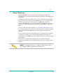
NOTE: Follow guidelines in this, or the previous, paragraph to use the
Quick Eagle Networks product more effectively.
CAUTION: Follow guidelines in this, or the previous, paragraph to
avoid equipment damage or faulty application.
WARNING: Follow the instructions in this, or the previous, paragraph
to avoid personal injury.
ELECTRO-STATIC DISCHARGE — CAUTION: Follow the instructions in
this, or the previous, paragraph to avoid the discharge of static
electricity, and subsequent damage to the equipment.
xviii
DL3800E Inverse Multiplexer User’s Guide — July 9, 2001
Typography
Quick Eagle Networks manuals delineate the names of files, commands,
and actions by using the fonts and typefaces described in the following
table:
Typeface or
Symbol
Purpose
Courier
Font
AaBbCc123
The names of commands, files, and
directories, as well as on-screen
computer output.
Edit your.login file.
Courier
Font, Bold
AaBbCc123
The input you provide, as contrasted
with on-screen computer output.
machine_name% su
Keystrokes that you must provide to
use the application.
Press Ctrl-L to refresh the screen.
Palatino Font,
Italic
AaBbCc123
Command-line placeholder that you
replace with a real name or value.
To delete a file, type rm filename
Book titles, new words or terms, or
words that need to be emphasized.
Refer to Chapter 6.
Example
Use ls -a to list all files.
machine_name% You have
mail.
These are called class options.
You must be logged in as root to
access this directory.
▼
Zapf Dingbats
Font
Symbol that denotes a single-step
procedure or task. Procedures
requiring more than one task are
numbered.
Palatino Font,
Bold Blue,
Underscore
AaBbCc123
Hyperlinks in the table of
contents.When viewing the Portable
Document Format (PDF) version of this
user guide, you can click on one of
these to jump directly to the selected
subject matter.
Palatino Font,
Blue
AaBbCc123
or
AaBbCc123
Hyperlinks throughout general text.
Helvetica Bold Denotes actual markings on front or
back panels.
Preface
Attach the cable to the TERMINAL
port
xix
QUICK EAGLE NETWORKS TECHNICAL SUPPORT
If you should experience difficulty with the setup and/or operation of
your Quick Eagle Networks equipment, the Quick Eagle Networks
Technical Support staff can assist you at any time.
Telephone
(408) 745-4200
FAX
(408) 745-4240
E-mail
[email protected]
Internet
www.quickeagle.com
RETURNING A UNIT
Use the following procedure if you need to return a unit for service or
repair,
1. Contact the Quick Eagle Networks Customer Service Department
at (408) 745-4200, or via e-mail at [email protected], or fax a
request to (408) 745-4240 to obtain an ERA (Equipment Return
Authorization) number.
2. Package the unit carefully and, before sealing the shipping carton,
include any information you can provide about the problems you
are currently experiencing with the unit.
3. Attach an address label to the shipping carton. Be sure to include
the ERA number:
Customer Service Department
Quick Eagle Networks
217 Humboldt Court
Sunnyvale, CA 94089
ERA # ___________
xx
DL3800E Inverse Multiplexer User’s Guide — July 9, 2001
SEND US YOUR COMMENTS
Please let us know if this user guide manual meets your requirements.
Does the manual answer your questions?
Is the manual thorough?
Is the manual easy to use; that is, can you find the information you need?
Is anything missing from the manual?
What would you like to see in the manual?
Quick Eagle Networks Technical Publications
FAX
(408) 745-6250
E-mail
[email protected]
All suggestions and comments are appreciated.
DOCUMENT CHANGE RECORD
Date
Issue Rev.
Description
Pages Affected
May 1996
A
Initial Release
All
January 1999
B
Update & Misc.
Changes
All
January 2000
C
Update & Misc.
Changes
All
September 2000
D
Update & Misc.
Changes
All
October 2000
E
Update & Misc.
Changes
All
June 2001
F
Update & Misc.
Changes
All
Preface
xxi
xxii
DL3800E Inverse Multiplexer User’s Guide — July 9, 2001
Quick Install Guide
1
1
PURPOSE
This chapter is a quick reference for the setup and configuration of the
DL3800E Inverse Multiplexer (see Figure 1-1). Please note that not all
configuration items will be discussed, because this chapter only serves to
get you up and running.
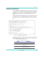
Figure 1-1
DL3800E Inverse Multiplexer (front panel)
CONFIGURATION
Equipment Needed
•
•
•
•
•
•
•
•
•
Terminal or PC, with DE-9 port, that will emulate an ANSI VT100
DL3800E E1 Inverse Multiplexer product (various ports)
The DL3000E comes either with BNC or 120 ohm
DE-9 cable (plug-socket) 154-00050-01 (Model DL1081) or equivalent.
DA-15 (plug) to RJ-48 (plug) for E1 connections 155-00011-01 (Model
DL1033) or equivalent.
HSSI or 155-10082-01 (HSSI) (Model DL1404-10) or equivalent
M-34 to DB-25 cables (v. 35) or 155-00903-01 (v. 35) (Model DL1300-10,
or equivalent
DC-37 to DB-25 (RS-449) 155-00902-01 (RS449) (Model DL1302-10) or
equivalent
X.21+DB-25 (X.21) 155-00907 (DL1314-10) and 155-00907-12 (DL1314-50)
(Model ID1314-10 and -50) or equivalent
1-1
1
Setup
Terminal Log On
Connect your terminal to the COMM port on the back of the DL3800E unit.
Before you can log into the unit, you must make sure that terminal settings
match the DL3800E. Defaults for the DL3800E unit COMM port: 9600
baud, no parity, 8 bit word length, 2 stop bits. To log into the unit, first
press Ctrl-x five times (that is, hold down the control key on the
keyboard and press the x key five times. This gives you the unit number.
Now type Ctrl-x # Unit Number and press Return or Enter. When
prompted for user name and password press Return twice, and the Main
Menu on the DL3800E unit should appear. The default unit number is 0.
Terminal Configuration
Change only the configuration items listed below. Leave the other options
at the factory default settings. To make a change, note that you must press
the UP and DOWN ARROW keys to highlight the item, press the space bar
until the desired option displays, then highlight CONFIRM and press Enter
before exiting the menu.
Unit Configuration
Select Configuration from the Main Menu. Select Unit Configuration. Set
the time and date. Set unit number other than zero. Select Confirm, then
select EXIT to go back to the CONFIGURATION MENU.
DTE Configuration
WARNING: V.35/RS449/X.21 will only work at a higher data rate
with a DTE that can give terminal clocking, when in SCTE mode.
Configure the DTE interface for either v.35/RS449/x.21 or HSSI. For
V.35/RS449/X.21 configuration, set the clock to SCTE and Normal TD/RD
clock. Set the DTE loss condition for NONE. Select Confirm, then select
EXIT to go back to the CONFIGURATION MENU.
1-2
DL3800E Inverse Multiplexer User’s Guide — July 9, 2001
1
Network Configuration
Set up a port for each E1 line you plan to use. Set Alarm to Report. Set
ACTICVE/RESTORE MODE to Use w/auto restore. Normally is CRC4
enable. Primary clock Xmt=Network (assuming carrier or remote unit
providing timing). Primary clock RCV should be set to AUTO. Configure
SER to Immediate Confirm and select EXIT. Select Exit again to the Main
Menu.
Save Configuration
Select SAVE CONFIGURATION from the Main Menu.
You’re done! If you have any questions, please feel free to call Quick Eagle
Network’s Technical Support at (408) 745-4200.
Quick Install Guide
1-3
1
1-4
DL3800E Inverse Multiplexer User’s Guide — July 9, 2001
Introduction
2
2
SYSTEM OVERVIEW
The DL3800E Inverse Multiplexer bridges the gap between E1 and E3 data
services by providing E1 multiplexing of multimegabit (up to Nx1.976
Mbps) DTE data onto two to eight E1 circuits. The DL3800E Inverse
Multiplexer is an economical solution to bandwidth intensive applications
as it provides multimegabit data transport without the need for E3 circuits.
The DL3800E unit is an ideal solution for applications such as LAN-toLAN internetworking, bulk data transfer, video teleconferencing, and
disaster recovery.
Figure 2-1
DL3800E Inverse Multiplexer
The inverse multiplexing technique employed by the DL3800E unit is
completely transparent to the DTE application, as the multiple E1 circuits
act as a single high-speed data link. The DL3800E unit can accept up to a
31-millisecond differential delay between individual E1 circuits, thus
providing the capability to accommodate E1 circuits from divergent paths.
This is often the case with circuits being utilized from different carriers.
An excessive delay alarm will cause an E1 line to be taken out of service. If
the relative delay between all the E1 lines exceeds 31 milliseconds, then the
E1 lines are removed from service one port at a time until the remaining
group reside within the 31-millisecond window. The first port taken out of
service will be the one that is farthest away from the average value,
regardless of its relative delay value. In order to restore an E1 line, you
must use the manual restore command. In order to bring an E1 line back
into service, execute the manual restore command on the remote unit first.
Then execute the manual restore command on the local unit. Auto restore
will not work for lines removed due to excessive delay.
The DL3800E unit supports either High Speed Serial Interface (HSSI) or
V.35/RS449/X.21 interfaces to the DTE.
2-1
2
The DL3800E unit features an automatic rate fallback in the event of a
failing E1 circuit. If the performance of an E1 circuit is detected to be
falling below accepted levels, the DL3800E unit automatically removes the
E1 from service, and throttles back the DTE to a data rate corresponding to
the remaining E1s. When the alarm condition on the affected E1 has been
cleared, the DL3800E unit can automatically restore the E1 and data rate.
You can configure, control, and monitor the DL3800E unit through the
front panel, an ASCII terminal (locally or remotely via a modem or
remotely in-band) or a Simple Network Management Protocol (SNMP)
management station. The remote DL3800E unit can be managed in-band
using overhead in all active connections as the communications path. The
DL3800E unit features an integrated SNMP agent which supports the E1
Management Information Base (MIB) in addition to a unit specific
enterprise MIB.
A downloadable software feature of the DL3800E unit allows new features
and functionality to be added to the unit on line (without interrupting the
data) via the unit's built-in communications port, or via a selected E1
connection.
PRODUCT FEATURES
The DL3800E Inverse Multiplexer allows you to connect high-speed data
terminal equipment (DTE) to multiple E1 links, providing aggregate data
rates up to 15.808 Mbps. Utilizing up to eight E1 links simultaneously, the
DL3800E unit is ideally suited to high bandwidth applications such as
LAN-to-LAN internetworking, video teleconferencing, bulk data transfer
and high-speed data recovery.
System Features
•
•
•
•
High bandwidth data transmission over 1 through 8 E1 ports.
HSSI or V.35/RS449/X.21 DTE interface
Automatic Bandwidth response/recovery
Local or remote management via front panel, terminal, or embedded
SNMP agent
• Extensive diagnostics:
• Front panel indicators
• Built-in test loops
• Automatic self test
• Integral event log with nonvolatile memory
2-2
DL3800E Inverse Multiplexer User’s Guide — July 9, 2001
2
System Benefits
The numerous features of the DL3800E unit provide you with many
benefits:
• Reliable, full performance access to E1 networks for the widest variety
of DTE products
• Enterprise wide visibility via SNMP
• Local and remote access via front panel, terminal, or telnet
• Complete maintenance and diagnostic support via exhaustive alarm,
statistic, and test capabilities
• Downloadable code provides for on-line upgrade to the DL3800E unit
software for both major and minor feature enhancements
Application
The DL3800E unit accepts data from a high-speed bridge, router, front-end
processor or other DTE device and multiplexes the bit stream onto one
through eight E1 circuits for transmission at N x 1.976 Mbps. Because the
inverse multiplexing process is completely transparent to the attached
equipment, the combined E1 circuits appear as a single high-speed data
link to the DTE. The DL3800E unit accepts up to a 31-millisecond
differential delay between individual E1 circuits, ensuring reliable
operation in multiple carrier networks.
A unique feature of the DL3800E unit is the automatic bandwidth response
to an E1 signal loss or network errors. If an E1 link falls below acceptable
performance levels, the DL3800E unit removes the link from service and
reduces the DTE data rate to correspond with the remaining E1 links in
service. When the alarm condition has been cleared, the DL3800E unit
restores the E1 link and increases the DTE data rate to its original level.
A typical application is shown in Figure 2-2.
Figure 2-2
Typical Application for DL3800E
Introduction
2-3
2
FUNCTIONAL DESCRIPTION
The base DL3800E unit configuration consists of a motherboard with two
(E1) network interface connectors and the DTE connectors (HSSI and
V.35/RS449/X.21). Six additional E1 network ports can be added with the
addition of from one to three daughterboards, each daughterboard
supporting two additional E1 ports.
The general operation of the DL3800E unit is explained in the following
paragraphs which describe the signal flow and overhead functions.
Signal Flow
The DL3800E unit is configured by you for the number of E1 signals to be
used for transmission. The DL3800E unit will provide a smooth clock to the
DTE at the data rate required for the number of E1 outputs you have
configured. For E1, this rate will be Nx1.976 Mbps, where N is the number
(1 to 8) of E1s to be used.
The transmit smooth clock PLL can use any of the incoming E1 clocks, an
external clock, or internal clock as reference. The receive smooth clock will
use one of the receive clocks at its source. The smooth clock VCO will be
divided down to 8 kHz to be phase compared to the 8 kHz reference. The
receive buffers are large enough to accommodate variations between E1
receive clocks.
The DL3800E unit supports one DTE interface. For data rates up to 6 Mbps,
the DTE interface can be HSSI or V.35/RS449/X.21 (software selectable).
For data rates over 6 Mbps, only the HSSI interface will be supported.
Data is sent from the DTE interface to an Inverse Multiplexer (IMUX)
transmit framer. A 16-bit proprietary framing pattern is defined to satisfy
the requirements of inverse multiplexing communications. This frame is
constructed by using one payload bit in each frame for 16 consecutive
frames. For E1, the inverse multiplexing frame is the first bit after the
framing bit.
From the inverse mux framer, the data is sent to all E1 framers, where the
E1 framing is added, and then to the appropriate E1 network interface and
out over the E1 network.
All incoming configured E1 lines, with their respective clocks, are received
into a standard E1 framer. The output of the E1 framer is fed into the IMUX
framer.
Data coming into the DL3800E Inverse Multiplexer is stored in N
independent buffers, where N is the number of configured input channels.
From these buffers, the data will be read and IMUX framing removed.
2-4
DL3800E Inverse Multiplexer User’s Guide — July 9, 2001
2
When the incoming signal is framed on the inverse mux frame, the framer
will start loading its Dual Port RAM. The address to the Dual Port RAM is
derived from the 16-bit inverse mux frame. The software will ask all
framers to latch their Dual Port RAM addresses at the same time, and by
looking at the addresses, the software can determine which network has
experienced the greatest delay.
From the receive inverse IMUX framer, the incoming data will go to the
receive multiplexer. The net that is last in time will be enabled to tell the
receive multiplexer when to start unloading the Dual Port RAM to the DTE
interface. To allow for jitter and wander specifications, the read address
counter will be positioned approximately three frames behind the write
address for the network last in time.
E1 Port Crossover Detection
When the IMUX E1 circuits synchronize, they use the IMUX framing to
communicate to know the ports (1-8). A crossover is a situation where a
network line is connected to a port on the remote 3800E different from the
port it originates from on the local 3800E.(e.g. port 1 on the local unit is
connected to port 2 on the remote unit). This situation will cause DTE
traffic to be incorrectly multiplexed and, as a result, severely errored.
When a crossover is detected, the DL 3800E removes the crossed port from
the DTE data bundle and reduces the DTE data rate. The LED will change
to flashing green and the port status in the Alarms & Status menu read
“Line crossed”, and also (Crossed to port:x), where x is the port number
connected at the remote end. It also generates an SNMP alarm:
enCrossoverAlarm.
When the crossover is cleared, the port is restored to DTE bundle and the
LED restores to green. Port crossover status clears and the SNMP alarm
enCrossoverAlarm is idled.
An IMUX E1 circuit is reestablished as soon as the mismatched circuits are
disconnected and reconnected properly.
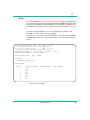
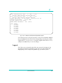
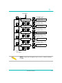
Figure 2-3 is a functional schematic of the DL3800E unit showing a unit
supporting four E1 lines.
Introduction
2-5
2
T
X
F
I
F
O
TX_
DTE
INTF
RX_
DTE
INTF
R
X
F
I
F
O
TX LCA
IMUX Framer
RX
LCA
E1 Framer
E1 TX Int.
E1 Framer
E1 TX Int.
E1 Framer
E1 TX Int.
E1 Framer
E1 TX Int.
IMUX Buffer
IMUX Framer
E1 Framer & RX Int.
IMUX Buffer
IMUX Framer
E1 Framer & RX Int.
IMUX Buffer
IMUX Framer
E1 Framer & RX Int.
IMUX Buffer
IMUX Framer
E1 Framer & RX Int.
Figure 2-3
DL3800E Unit Functional Schematic
Overhead Functions
The overhead functions consist of a controller, front panel, two RS232
communication interfaces (terminal and network management), and a
power supply.
The controller function is performed by a microprocessor on the main
board. The controller collects E1 statistics. It also processes E1 alarms and
performance monitoring information, as well as supporting unit
configuration, test and maintenance activities. Finally the Controller block
supports the front panel display, terminal port, and SNMP port interfaces.
The front panel consists of a 16-character vacuum fluorescent display,
4-key keypad, and LEDs. This panel can be used to provision the unit, run
diagnostic tests, or access performance statistics.
The serial ports are RS-232C compatible ports with one port supporting a
menu driven ASCII terminal interface, and the other port providing access
to the built-in SNMP agent functionality.
The DL3800E unit can be ordered with DC or AC power supplies and the
built-in power supply has a range of 110 to 240 VAC and -40 to -75 VDC.
2-6
DL3800E Inverse Multiplexer User’s Guide — July 9, 2001
Installation
3
3
INSTALLATION
NOTE: Before beginning the installation process, inspect the DL3800E
unit for damage which may have occurred during shipment. If damage
has occurred, notify Quick Eagle Networks and your package carrier
immediately.
1. Unpack and inspect the DL3800E unit for damage that might have
occurred during shipment. If necessary, wipe off the exterior with
a soft cloth. Save all packing slips and papers that come with the
unit. Save the shipping cartons and packing materials until
installation is complete and proper operation is verified.
2. Verify that all items ordered are included in the shipment. The
shipment should consist of the following:
• DL3800E Digital Inverse Multiplexer
• DL3800E User’s Guide (this manual).
• Appropriate data and network interface cables and connectors (if
ordered).
• Power cord
3. Mount the DL3800E unit.
See “Mounting” on page 3-2.
4. Connect Power Cables and Connections.
See “Power Cables And Connections” on page 3-3
5. Connect network cables to the DL3800E unit.
See “E1 Network Connection” on page 3-5
6. Connect the DTE cable to the DL3800E unit.
See “DTE Cable And Connection” on page 3-5
7. ASCII Terminal and SNMP Connection
See “ASCII Terminal and SNMP Connection” on page 3-6
3-1
3
8. Configure Unit
See “Unit Configuration” on page 4-17 (ASCII terminal)
a. Configure COMM PORT
See “Unit Configuration” on page 4-17 (ASCII terminal)
b.
Configure NMS (Network Management) Port
See “SNMP Configuration” on page 4-39 (ASCII terminal)
9. Configure Network
See “Network Configuration” on page 4-25 (ASCII terminal)
10. Configure DTE
See “DTE Configuration” on page 4-20 (ASCII terminal)
MOUNTING
Rack Mounting
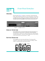
The DL3800E unit (Figure 3-1) is shipped with mounting ears for a 19- or
23-inch rack that are mounted for use with a 19-inch rack.
Desk Operation And Stacking
Four stick-on rubber feet are supplied with each DL3800E unit. Remove the
covering and stick them onto the DL3800E unit bottom. You can now stack
units as required on a flat surface in a well-ventilated, secure area.l
Figure 3-1
DL3800E Rear Panel
NOTE: On DC versions of the DL3800E, the AC receptacle will be
covered with a DC face plate.
3-2
DL3800E Inverse Multiplexer User’s Guide — July 9, 2001
3
POWER CABLES AND CONNECTIONS
The DL3800E unit can be ordered with an AC or DC power supply.
AC Power Connection
An AC power cord is supplied with the DL3800E -AC-XXX to provide 120
to 240 VAC power. The power cord receptacle is located on the rear panel
of the DL3800E-AC-XXX. For AC power, connect the AC power cord to the
DL3800E-AC-XXX, and plug into the nearest AC outlet.
DC Power Connection
The Quick Eagle Networks DL3800E Inverse Multiplexer can also be
powered by a -48 VDC power source. The DC power connection on the
DL3800E is located on the back panel. There are eight screw terminals
located on the rear panel. The two screw terminals on the far right (looking
at the rear panel) are for DC power.
Connect the -48 V wire to the screw terminal labeled —. Attach the 48 V
Return(+) wire to the screw terminal to the immediate right, labeled +.
Connect earth ground to the ground stud.
When using DC power, you will need the following:
• A tray cable which must be UL recognized 14 AWG, 3 conductors,
copper strand.
• Electrical power and control cable type TC, 600 V 90°C. (Alpha Wire
Company No. 45443 is an example.)
To mechanically install the DL 3800E when using DC power, perform the
following steps:
1. Place the DL3800E unit on a flat surface or in a rack.
2. Before you connect the DL3800E unit to the centralized DC power
source, strip 2.0 inches of jacket material off the tray cable and
0.5 inch of insulation off each wire.
3. Connect the -48 VDC wire to the - terminal (on the rear panel’s
terminal block, using a small flat screw driver (¼-inch blade) to
fasten the wire.
Installation
3-3
3
4. Connect the ground (+) wire to the + terminal in the same way.
NOTE: The unit is designed to operate with negative voltage;
therefore, you must connect the positive terminal to ground.
5. Connect the frame ground terminal to the local earth ground, if
required.
6. To minimize disturbance to the wires through casual contact,
secure a tray cable near the rack frame using multiple cable ties.
Use at least four cable ties, a minimum of four inches apart. The
first tie should be within six inches of the terminal block.
7. Connect the DL3800E unit to a DC power source.
WARNING: Damage to the DL3800E unit may result if power is
connected improperly. Do not operate the DL3800E unit without a
ground connection to the ground stud.
The DL3800E unit automatically runs a self-test at power up, during
which the front panel displays a self-test message. Payload service resumes
upon completion of the self-test and the front panel displays the following
default message:
EFS 00.0 PERCENT
WARNING: Do not operate the DL3800E unit without an earth
ground connection to the ground stud.
The DL3800E unit is designed to operate with a negative power supply.
This means the positive terminal is connected to the ground.
WARNING: Damage to the DL3800E unit may result if power is
connected improperly.
3-4
DL3800E Inverse Multiplexer User’s Guide — July 9, 2001
3
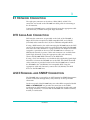
E1 NETWORK CONNECTION
The eight port connector can be either a DB-9, DB-15, or BNC. The
connectors are located on the DL3800E unit back panel for connecting to
the E1 networks.
Connect the DL3800E unit to each E1 Network using the appropriate cable
and connectors, available from Quick Eagle Networks.
DTE CABLE AND CONNECTION
DTE interface connectors are provided on the back of the DL3800E, a
50-pin SCSI socket receptacle for HSSI compatible DTE, and a DB-25
(E1A-530) socket connector for V.35/X.21 or RS-449 compatible DTEs.
If using a HSSI interface, the cable connecting the DL3800E unit to the DTE
consists of 25 twisted pairs with an overall foil/braid shield. The DL3800E
unit end of the cable should have a plug connector. One 50-pin SCSI socket
receptacle is provided on the rear of the DL3800E unit to connect it to
HSSI-based networks/systems. Cables and connectors are available from
Quick Eagle Networks. Using the appropriate cable and connectors,
connect the DL3800E-HSSI connector to the HSSI DTE.
If using a V.35/X.21 interface, use a shielded cable supplied by Quick Eagle
Networks to connect the DL3800E unit to the DTE. One DB-25 (E1A-530)
socket connector is provided on the back of the DL3800E unit to connect
the DL3800E to the V.35/RS-449/X.21 compatible DTE. Using the
appropriate cable and connectors, connect the V.35/RS-449/X.21 DTE
device to the DL3800E unit.
ASCII TERMINAL AND SNMP CONNECTION
The DL3800E unit is accessed by an ASCII terminal or SNMP Management
System workstation through direct, daisy-chained, or dial-up modem
connection.
On the rear panel of the DL3800E unit, two socket DE-9 receptacles labeled
NMS and COMM PORT are provided for connection to the SNMP
workstation or ASCII terminal, respectively. An RS-232 straight cable, with
DE-9 plug connectors, is used to link the DL3800E unit with the terminal,
modem, or workstation.
Installation
3-5
3
Direct Connection
For direct connection, using the appropriate DE-9 cable, connect the ASCII
terminal or SNMP workstation to the DL3800E unit through the Terminal
or SNMP connector on the back of the rear panel. The baud rate, parity bit,
and stop bit settings must match those of the terminal: baud rate, 9600;
eight bits, no parity and two stop bits.
Modem Connection
When using a modem, the baud rate, parity bit, and stop bit settings of the
modem must match the terminal or workstation port default settings: baud
rate 9600; eight bits; no parity, and two stop bits. If these parameters are
not the same, reconfigure the unit default settings using the front panel
controls.
When the parameters of the modem and the terminal or workstation port
coincide, using the RS-232 straight cable, connect the modem to the
appropriate RS-232 comm port (COMM PORT or NMS) on the rear panel of
the DL3800E. Then, connect the modem to the phone line and the ASCII
terminal or SNMP workstation. DE-9 to DB-25 adapters and null-modem
adapters are available from Quick Eagle Networks. Specify a plug or socket
terminal connection when ordering.
For direct connection, the terminal, workstation, or modem may be placed
up to 15 meters away from the comm port when operating at 9600 baud.
Distances may be increased if the baud rate is reduced.
Telnet Connection
For a telnet connection, connect a device that provides a SLIP connection to
the NMS port of the DL3800E unit. Examples include a terminal server,
router auxiliary port, or the Quick Eagle Networks Management Access
Processor (MAP). Be sure to provide a valid IP address to the DL3800E.
There can be up to two active telnet sessions at any given time. There is no
way for a user to delete the telnet session of another user.
3-6
DL3800E Inverse Multiplexer User’s Guide — July 9, 2001
3
Daisy Chaining
Multiple DL3800E units can be daisy-chained together through the
Terminal Port to provide centralized network monitoring and management
capabilities.
A ribbon-type cable with DB-9 connectors is available from Quick Eagle
Networks for daisy-chaining your DL3800E units. You can order specific
cables to daisy-chain four units (Part No. 154-00051-01), eight units
(Part No. 154-00052-01), or twelve units (Part No. 154-00053-01). To place an
order, contact the Quick Eagle Networks Sales Department at (408) 7456200.
If using a cable other than the above, see “Terminal Connection” on page
B-1 for Terminal Port pin assignments. With this cable, CTS (pin 8) must be
connected between DL3800E units, but must not be connected to the
terminal.
The one socket connector on the ribbon is to be connected to the terminal
or modem (if a remote site). The remaining plug DE-9 connectors are
connected to the DL3800E1 unit port. Each unit must be assigned a unique
node number.
When units are daisy-chained together, the local terminal must be
operating in Multidrop Mode. Each unit should be given a unique Node
Number.
NOTE: For detailed instructions on installing SNMP systems, refer to
the separate installation guides for these products.
Installation
3-7
3
3-8
DL3800E Inverse Multiplexer User’s Guide — July 9, 2001
Terminal Interface
4
4
LOG IN/LOG OFF
Each DL3800E unit is equipped with an integrated RS-232 ASCII user
interface that can be accessed through the COMM PORT (DE-9 connector)
located on the rear panel of the DL3800E. Through this interface, you can
perform various functions described in this section.
When operating in multidrop mode (that is, when multiple DL3800E units
may be daisy-chained together for centralized network management), you
must log in to establish communication with a single unit on the network.
Only one unit may be accessed at a time. All units continuously monitor
the line, but only the unit which is logged on will respond to terminal
commands. When no unit is logged on, the characters typed on the
terminal will not show up on the display screen.
To log on and log off a particular unit, follow these procedures:
1. Type five Ctrl-X commands in a row to return a “roll call” of all
Node Numbers on the chain.
This feature is useful when the Node Numbers of any units on the
network are unknown.
2. Type Ctrl-X followed by #, the node number, and press Enter (or
Return).
These characters will not be displayed on the terminal screen, but
the units will receive them.
If passwords are enabled for the unit, you will be prompted for the
username and password. Initially, no password or username is
needed, so simply press Enter when prompted for a username or
password.
3. The Main Menu will appear. If not, check that the Node Number
matches what is typed on the terminal.
If it still does not appear, check that the DL3800E unit port settings
match the terminal settings (baud rate, parity, data bits, and stop
bits). If so, a null modem adapter may be required to interchange
pins 2 and 3 (transmit and receive) from the terminal.
4-1
4
4. To log on to another DL3800E unit on the same daisy chain,
simply type Ctrl-X, followed by a # and the Node Number and
press Enter.
The previous unit is logged out and the new unit is logged on.
5. To log off all units without logging onto any new units, press
Ctrl-X at the Main Menu.
TERMINAL OPERATION OVERVIEW
General Menu Flow
The menu interface for the DL3800E unit consists of the Main Menu, and a
series of submenus.
From the Main Menu, select the submenu to be selected or function to be
performed by moving the highlight bar through the menu screen with the
Cursor Arrow keys until the desired function is highlighted.
To prevent any accidental data and/or status change, every proposed
change requires a confirmation response. To confirm a proposed change,
move the highlight bar to Confirm on the menu and press Enter. Type any
other key and the change will not be made. This will cause the terminal to
continue to prompt you to confirm the change(s). To abort the change,
move the highlight bar to Exit, and press the Enter key rather than
confirming the change.
NOTE: Pressing the Escape key brings the display back to Select
Local/Remote when in the Main Menu, and back to Exit when in the
EXECUTION MENU.
Screen Description
The top four lines of each display screen contain information regarding the
last two status or alarm conditions reported by the DL3800E unit. This
information includes: the severity of condition reported; the date and time
condition was reported; the Unit and NET (E1 port) reporting the alarm; a
code for the type of condition, and a description of the condition.
4-2
DL3800E Inverse Multiplexer User’s Guide — July 9, 2001
4
The next two lines in the menu, which are always highlighted, represent
the Status Bar. The first line of the Status Bar displays the product type, the
software release number, node number, node name, date & time, and
current alarm status of the unit. The second line displays the selected
device address and name.
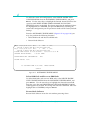
Major 01/01/90 04:58:17 Unit: 0
NET : 2 (114)
Network 15 Minute UAS Major Threshold Exceeded
Major 01/01/90 04:58:17 Unit: 0
NET : 1 (114)
Network 15 Minute UAS Major Threshold Exceeded
Digital Link DL3800E
SR 3.00.00 NODE 7: 01/01/90 05:55:07
SELECTED DEVICE ADDRESS:
7.00.000 NAME:
MN
INVERSE MULTIPLEXER MAIN MENU
Select Local/Remote
Alarms & Status
Statistics
Event History
Configuration
System Utilities
Tests
Manual Network Restoration
Logout
Figure 4-1
INVERSE MULTIPLEXER MAIN MENU
The product type is a DL3800E Digital Inverse Multiplexer.
The software revision is 3.XX, where xx equals the latest software revision.
This number is useful to determine the features that are supported with
this release.
The Node number, in this case 7, is user defined. This can be used to
further identify the node within your network. It is recommended that all
nodes be given a unique node number. This is crucial in inter-node
communications.
The Node name (HOME), is user defined. You can use this field to uniquely
describe the node within the network.
The date and time are give in mm/dd/yy, and hh:mm:ss format.
The alarm indicator, in this case MN for minor, is given on each screen to
alert you of a local Node alarm.
The Selected Device address, in this example 7.00.000 is shown at the
beginning of the second status line. A device is a generic term to indicate a
NODE (unit).
Terminal Interface
4-3
4
INVERSE MULTIPLEXER MAIN MENU COMMANDS
When a DL3800E unit is first powered up, the Main Menu (Figure 4-1 on
page 4-3) appears on the terminal screen. This describes those functions
that can be performed, parameters viewed, changed and/or deleted from
this menu. The INVERSE MULTIPLEXER MAIN MENU items are shown
in Table 4-1 (these items are described in more detail in the following
sections)..
Table 4-1
Main Menu
Menu
Description
Select Local/Remote
Allows you to move between the Main Menu of the Local and Remote
units.
Alarms and Status
Provides current alarm and status report of the common equipment, DTE,
and E1 lines.
Statistics
Allows you to access the STATISTICS MENUS of the various E1 lines.
Event History
Allows user to view and clear alarms and event history of the DL3800E.
Configuration
Allows you access submenus to configure certain parameters of the
DL3800E, network, and DTE.
System Utilities
Allows you to perform various system utility functions such as download
software, configure SNMP, configure login, and delete or save
configuration.
Tests
Allows you to initiate diagnostic loopbacks.
Manual Network Restoration
Allows you to manually restore a E1 circuit instead of it being restored
automatically upon the clearing of a problem.
Logout
Allows you to log out of the DL3800E unit without having to wait for
automatic logout.
SELECT LOCAL/REMOTE
When in the INVERSE MULTIPLEXER MAIN MENU, this option allows
you to view and access the other items on either the local or remote
DL3800E. The Device Address and Name in the header portion of the
display screen will identify the unit that the terminal is presently
communicating with.
To move to the Main Menu of the other DL3800E, highlight SELECT
LOCAL/REMOTE and press Enter. The Device Address and Name in the
header should change to the new unit as shown in Figure 4-1 on page 4-3.
4-4
DL3800E Inverse Multiplexer User’s Guide — July 9, 2001
4
ALARMS AND STATUS
The ALARMS AND STATUS MENU is a view-only screen that allows you
to review the current ALARMS AND STATUS items being reported by the
DL3800E. To access this screen, move the highlight bar in the INVERSE
MULTIPLEXER MAIN MENU to ALARMS AND STATUS and press
Enter.
The ALARMS AND STATUS display (Figure 4-2) will appear on the screen
describing the status of the common equipment and each of the E1 ports
(lines), plus the status of the DTE leads and the current rate of the DTE
port.
Major 01/01/90 04:58:17
Network 15 Minute UAS
Major 01/01/90 04:58:17
Network 15 Minute UAS
Digital Link DL3800E
SR
SELECTED DEVICE ADDRESS:
Unit:
0
NET : 2 (114)
Major Threshold Exceeded
Unit:
0
NET : 1 (114)
Major Threshold Exceeded
2.00.00 NODE 7:
01/01/90 05:55:07
7.00.000 NAME:
CURRENT ALARMS AND STATUS ITEMS
Exit
MJ
Repeat
Common equipment status: No Ext Clk, Primary Clk, No Net Sync
Network ports:
PORT 1: LOS, RED, Active, OOF MN, UAS 15 MIN MJ Relative delay of 0.000 ms
PORT 2: LOS, RED, Active, OOF MN, UAS 15 MIN MJ Relative delay of 0.000 ms
PORT 3: BPV MN, OOF MN, BPVS 15 MIN MN
PORT 4: BPV MN, OOF MN, BPVS 15 MIN MN
PORT 5: LOS, RED, UAS 15 MIN MJ
PORT 6: LOS, RED, UAS 15 MIN MJ
PORT 7: LOS, RED, UAS 15 MIN MJ
PORT 8: LOS, RED, UAS 15 MIN MJ
RS449/X.21 port: DSR ON
Current RS449/X.21 port rate = 3.952 Mbits/sec
Figure 4-2
ALARMS AND STATUS MENU
Following are the Alarm and Status items (severity) that may appear. The
Common Equipment alarms and status will appear first, followed by the
Network and the DTE alarms and status.
Table 4-2
3800E Alarm Descriptions
ALARM
DESCRIPTION
NETWORK
LOS
Loss of Signal -- Net Port does not detect
any E1 pulses
LOF
Loss of Frame - Net Port does not detect a
valid E1 framing format
Terminal Interface
4-5
4
Table 4-2
3800E Alarm Descriptions
ALARM
4-6
DESCRIPTION
AIS DET
Alarm Indication Signal Detected — Net
Port detects an unframed continuous
stream of binary ones.
AIS
Alarm Indication Signal — Not used.
YEL Det
Yellow Alarm (RAI — Remote Alarm
Indication) Detected. #Net Port detects the
presence of an RAI.
YEL
Yellow Alarm (RAI) - Net Port transmits a
Yellow Alarm (RAI) when receiving an AIS,
LOS, or LOF.
Failed Signal
Not used.
Xmt Failed
Not used.
User Line Lpbk
User Line Loopback – Net Port in a Line
Loopback. Enabled by you under the Tests
menu.
User Payload Lpbk
User Payload Loopback – Net Port in a
Payload Loopback. Enabled by you under
the Tests menu.
HW Line Lpbk
Not used.
HW Payload Lpbk
Not used.
Remote Lpbk
A loopback is occurring on the net lines or
on the remote unit.
*Active
Net Port is Active. This indicates that the
Net Port is part of the bundle passing data
to and from the DTE port.
Not Active
Net Port is Inactive. This indicates that the
Net Port has been removed from the
bundle and is no longer passing data to
and from the Data Port.
Excessive Delay
The Net Port has exceeded the 31ms
relative delay.
Set Code Detected
The Net Port has detected a Loop code
sent from the Network.
Reset Code Detected
Net Port has detected a Loop down code
sent from the Network.
CRC Threshold
Net Port has exceeded the CRC Threshold.
DL3800E Inverse Multiplexer User’s Guide — July 9, 2001
4
Table 4-2
3800E Alarm Descriptions
ALARM
DESCRIPTION
SES Threshold
Net Port has exceeded the Severely
Errored Second Threshold.
UAS Threshold
Net Port has exceeded the Unavailable
Second Threshold.
BPV MN/MJ
Net Port has declared a Bipolar Violation
Major or Minor Alarm.
OOF MN/MJ
Net Port has declared an Out Of Frame
Major or Minor Alarm.
BPVs 15 Min. MN/MJ
Net Port has declared a Bipolar Violation
15 minute Major or Minor Alarm
CRCs 15 Min. MN/MJ
Net Port has declared a CRC 15 minute
Major or Minor Alarm
ES 15 Min. MN/MJ
Net Port has declared a Errored Second
15 minute Major or Minor Alarm
SES 15 Min. MN/MJ
Net Port has declared a Severely Errored
Second 15 minute Major or Minor Alarm.
UAS 15 Min. MN/MJ
Net Port has declared a Unavailable
Second 15 minute Major or Minor Alarm.
BPVs 24 Hr MN/MJ
Net Port has declared a Bipolar Violation
24 Hour Major or Minor Alarm.
CRCs 24 Hr MN/MJ
Net Port has declared a CRC 24 Hour
Major or Minor Alarm.
ES 24 Hr MN/MJ
Net Port has declared a Errored Second
24 Hour Major or Minor Alarm.
SES 24 Hr MN/MJ
Net Port has declared a Severely Errored
Second 24 Hour Major or Minor Alarm.
UAS 24 Hr MN/MJ
Net Port has declared a Unavailable
Second 24 Hour Major or Minor Alarm.
COMMON EQUIPMENT
External Alarm
An External Alarm has been detected. This
alarm is based on the External Alarm
contacts on the back panel.
Proc Restart
Unit has rebooted.
RAM Test Fail
This occurs if the unit’s RAM does not pass
the memory test which occurs at startup.
Terminal Interface
4-7
4
Table 4-2
3800E Alarm Descriptions
ALARM
DESCRIPTION
ROM Checksum Fail
This occurs if the checksum for the code
image stored in ROM does not match that
expected.
No Ext Clk
No clock detected on the External Clock
DB-- 9 connector on the back panel.
Primary Clock
The set primary receive clock source is
now providing the network receive clock.
Secondary Clk
The set secondary receive clock source is
now providing the network receive clock.
(Occurs if the primary source has been
lost).
Internal Clk
Loss of Internal Clock.
Sync
Net 1 -- Net Port 1 is the network receive
clock source.
Sync
Net 2 -- Net Port 2 is the network receive
clock source.
Sync
Net 3 -- Net Port 3 is the network receive
clock source.
Sync
Net 4 -- Net Port 4 is the network receive
clock source.
Sync
Net 5 -- Net Port 5 is the network receive
clock source.
Sync
Net 6 --- Net Port 6 is the network receive
clock source.
Sync
Net 7 -- Net Port 7 is the network receive
clock source.
Sync
Net 8 -- Net Port 8 is the network receive
clock source.
No Net Sync
Shows all port are down. More
specifically, if a network clock cannot be
sourced from any port.
DTE
4-8
HSSI Channel Lpbk
A HSSI hardware loopback has been set.
User Lpbk
The DTE/Network loopback has been set.
V.35 LT Lpbk
A V.35 hardware loopback has been set.
DL3800E Inverse Multiplexer User’s Guide — July 9, 2001
4
Table 4-2
3800E Alarm Descriptions
ALARM
DESCRIPTION
DTE Loss
The signal indicating DTE presence has
been lost.
DTR On
The V.35 DTR signals is present.
RTS On
The V.35 RTS signal is present.
RLB On
The V.35 DTE Remote Loopback signal has
been set.
LT On
The V.35 LT signal is present.
TA On
The HSSI TA signal is present.
LA On
The HSSI LA signal is present.
LB On
The HSSI LB signal is present.
DSR On
The V.35 DSR is asserted.
CTS On
The V.35 CTS signal is asserted.
RLSD On
The V.35 RLSD signal is asserted.
TM On
The V.35 TM signal is asserted.
CA On
The HSSI CA signal is asserted.
LC On
Not used
Line crossed
E1 network lines are crossed.
Terminal Interface
4-9
4
NOTE: Status display will read ACTIVE, if the DL3800E unit is in
Inverse Mux mode and receiving I-Framing on the E1 without Blue,
Yellow, or Red Alarms or Major Alarm Thresholds being exceeded.
If the E1 Network Configuration is set to NEVER USE and a good E1
is connected, the Alarm & Status display will read NOT USED.
In Single DSU Mode, the DL3800E unit is Active if it is receiving
valid E1 pulses from the network without Blue, Yellow, or Red Alarms
or Major Alarm Thresholds being exceeded and 1) if, in HSSI mode,
the TA must be asserted or 2) if, in non-HSSI mode, you must select
DTR or RTS.
A Blue, Yellow, or Red Alarm or the exceeding of Major Alarm
Thresholds will cause the E1 to be taken out of service.
4-10
DL3800E Inverse Multiplexer User’s Guide — July 9, 2001
4
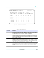
Statistics
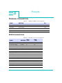
This menu allows you to access the performance STATISTICS SUBMENU
of any E1 port. Highlight STATISTICS in the INVERSE MUX MAIN
MENU, and press the Enter key. The STATISTICS MENU appears
(Figure 4-3).
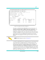
Major 01/01/90 04:58:17
Network 15 Minute UAS
Major 01/01/90 04:58:17
Network 15 Minute UAS
Digital Link DL3800E
SR
SELECTED DEVICE ADDRESS:
STATISTICS MENU
NETWORK
NETWORK
NETWORK
NETWORK
NETWORK
NETWORK
NETWORK
NETWORK
1
2
3
4
5
6
7
8
Unit:
0
NET : 2 (114)
Major Threshold Exceeded
Unit:
0
NET : 1 (114)
Major Threshold Exceeded
2.00.00 NODE 7: 01/01/90 05:55:07
7.00.000 NAME:
MJ
Exit
STATISTICS
STATISTICS
STATISTICS
STATISTICS
STATISTICS
STATISTICS
STATISTICS
STATISTICS
Figure 4-3
STATISTICS SUBMENU
Terminal Interface
4-11
4
To view the performance statistics of any one E1 port, highlight that port
and press Enter. The NET STATISTICS for that port (Figure 4-4) will
appear on the screen.
Figure 4-4
NET STATISTICS MENU
This screen displays the selected port’s E1 performance statistics for the
current 15-minute interval and for the past 48-hour interval. The
performance statistics for the first 24 hours are in both accumulative form
and in 15-minute intervals. The statistics for the second 24 hours are only
in accumulative form. It also allows you to clear the display and reset the
counters. For the DL3800E unit, the E1 statistics displayed are BPV, EB, FE,
ES, SES, BBE, UAS, EFS, ESR, SESR, and BBER.
To view additional pages with this set of performance data, press the
Cursor DOWN ARROW, or to view the previous page, press the Cursor UP
ARROW.
Additional NET STATISTICS are presented in subsequent screens. To view
additional screens with this same set of performance data, press the tab key
or the Cursor right and left arrow keys until the next field is highlighted,
then press Enter. Continue to press Enter with the NEXT field
highlighted to view all the screens.
This screen contains NET STATISTICS snapshots at 15-minute intervals.
4-12
DL3800E Inverse Multiplexer User’s Guide — July 9, 2001
4
DIGITAL LINK DL3800E SR 3.00.22 NODE
1:
SELECTED DEVICE ADDRESS:
1.00.000 NAME:
NET STATISTICS - PORT 1
CURRENT SECONDS: 563
ESR:
0.0%
Exit
Repeat
09/20/00 03:55:17
Clear
PAST INTERVALS: 192
SESR:
0.0%
Page
1
ERROR-FREE SECONDS: 100.0%
BBER:
0.0%
BPV
0
EB
0
FE
0
ES
0
SES
0
BBE
0
UAS
0
CUMULATIVE 1
0
0
0
0
0
0
0
CUMULATIVE 2
0
0
0
0
0
0
0
03:30-03:45
03:15-03:30
03:00-03:15
02:45-03:00
02:30-02:45
0
0
0
0
0
0
0
0
0
0
0
0
0
0
0
0
0
0
0
0
0
0
0
0
0
0
0
0
0
0
0
0
0
0
0
CURRENT
Figure 4-5
MJ
Additional NET STATISTICS
.
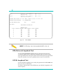
Table 4-3
NET Statistics Items
Parameter
Definition
EFS
Error Free Seconds (EFS) is calculated whenever ESR is calculated, and is the simple
percentage complement of ESR: EFS = 100.0 - ESR. When there have been UAS in
the statistics history for the past 24 hours, then EFS is set at 100%.
ESR
Errored Second Ratio (ESR) is the ratio of ES to total seconds in available time during
a fixed measurement interval. The fixed interval is the last 24 hours before the current
15-minute interval. When there have been UAS in the statistics history for the past 24
hours, then ESR is set at 0%.
SESR
Severely Errored Second Ration (SESR) is the ratio of SES to total seconds in
available time during a fixed-measurement interval. The fixed interval to be used is
the last 24 hours before the current 15-minute interval. When there have been UAS
in the statistics history for the past 24 hours, then SESR is set at 0%.
BBER
Background Block Error Ratio (BBER) is the ratio of errored blocks to total blocks
during a fixed-measurement interval, excluding all blocks during SES and unavailable
time. The fixed interval is equal to the last 24 hours before the current 15-minute
interval.
Terminal Interface
4-13
4
Table 4-3
NET Statistics Items (Continued)
Parameter
Definition
BPV
This display provides the number of Bipolar Violations (BPVs) that have occurred
during the accumulation period. A total of 15430 BPVs in a 10-second sliding
window (approximately 10-3) will create a Major Alarm and 916 BPVs in a
600-second sliding window (approximately 10-6) will create a Minor Alarm.
FE
A Frame Error (FE) is declared when two out of four consecutive framing bits are in
error. Typically, an FE indication will be accompanied by a significant number of
payload data bit errors. This display provides the number of FEs that have occurred
in the accumulation period.
EB/CV
An Errored Block (EB) is a block in which one or more bits are in error. The EB if
therefore equivalent to the Code Violation (CV) count calculated and displayed in the
previous versions of the DL3800E unit. This count allows you to monitor the rate of EB
faults on a line that is unavailable.
EBs are counted in the unavailable state; ES, SES, and BBE are not counted in the
unavailable state.
ES
An Errored Second (ES) is a one-second period with one or more errored blocks (such
as one or more CRC4 errors) or an Out Of Frame (OOF). This display provides the
number of ESs that have occurred in the accumulation period. ESs are not
accumulated during UAS.
SES
Severely Errored Seconds (SES) is a one-second period which contains 30% or more
errored blocks or at least one severely disturbed period (SDP). An SDP is present if
either a LOS, AIAS, or LOF occurs.
Since there are 1000 blocks per second, an SES is a one-second period which
contains either a combination of 300 or more CRC4 errors, an OOF, or at least one
of the following: LOS, AIS, or LOF. This requirement is a slight change from the prior
DL3800E unit SES definition, which required 320 or more CRC4 errors or LOS, AIS,
or LOF. SESs are not accumulated during UAS.
BBE
4-14
A Background Block Error (BBE) is an errored block not occurring as part of an SES.
A BBE is calculated and displayed as a raw count of non-SES EBs. The count is
updated at the end of every measurement second excepting any second that is an
SES. The updated count is discarded for all UAS.
DL3800E Inverse Multiplexer User’s Guide — July 9, 2001
4
Table 4-3
NET Statistics Items (Continued)
Parameter
Definition
UAS
Unavailable Seconds. This display provides the number of UAS that have occurred in
the accumulation period. At the onset of 10 consecutive SES events, a period of
unavailable seconds begins. These 10 seconds are part of the unavailable seconds
count. At the onset of 10 consecutive non-SES events, a new period of available time
begins. These 10 seconds are part of available time.
UAS occurs as soon as a Red Alarm is invoked (such as after two seconds of LOS.)
ES, SES, and BBE are not counted during unavailable time. Rate parameters ESR,
SESR, and BBER are the ratio of the fault-seconds count to the total seconds in
available time.
Event History
Use this screen to review and clear the DL3800E unit alarm and status
history.
To view the EVENT HISTORY, move the highlight bar to EVENT HISTORY
in the NODE MAIN MENU, and press Enter. Use the up and down keys
to move to the next or previous page of the EVENT HISTORY MENU.
Terminal Interface
4-15
4
Table 4-4
Alarm Level
Alarm Parameter
Definition
Alarm Level:
Major
Minor
Idled
Status
Service affecting
Needs attention, not yet service affecting
Alarm condition has expired
Non-service-affecting event
Date and Time
Date and time of the occurrence or expiration of the alarm/state
Address
The address is the physical location
Device
The device reporting the status and alarm condition (Unit #), and the type of device
(NET, DTE, or NODE)
Event Code
Number designation for type of alarm or status condition. This number will be
useful when contacting the factory
Description
Describes the event
To clear the report of all History Events, move the highlight bar to CLEAR
HISTORY and press Enter. Figure 4-6 is an example.
Major
01/01/90
17:56:47
Loss of Frame
Idled 01/01/90
17:56:58
Loss of Frame Idled
Unit: 1NET : 2(33)
Unit: 1NET : 2(13)
DIGITAL LINK DL3800E SR 2.00.000 NODE 7:HOME 01/01/90
03:14:54 MN SELECTED DEVICE ADDRESS: 7.00.000NAME:HOME
EVENT HISTORY
Exit
Repeat
Clear History
Idled
01/01/9009:02:10Unit 1NET 2
Yellow Signal Detected Idled
Major
01/01/9009:02:06Unit 1NET 2
Yellow Alarm
Status
01/01/9008:58:09Unit 1NET 2
Yellow Signal Detected
Idled
01/01/9008:58:01Unit 2NET 3
Yellow Signal Detected Idled
Minor
01/01/9008:56:24Unit 1Node
ROM Checksum Failed
Figure 4-6
4-16
(29)
(30)
(29)
(29)
(36)
EVENT HISTORY MENU
DL3800E Inverse Multiplexer User’s Guide — July 9, 2001
Page 1
4
Configuration
The CONFIGURATION MENU item provides access to a series of
submenus to configure various parameters of the unit, DTE, and network.
Highlight Configuration in the INVERSE MULTIPLEXER MAIN MENU
and press Enter to access the CONFIGURATION MENU. See Figure 4-7.
Major 01/01/90 04:58:17
Network 15 Minute UAS
Major 01/01/90 04:58:17
Network 15 Minute UAS
DIGITAL LINK DL3800E
SR
SELECTED DEVICE ADDRESS:
Unit:
0
NET : 2 (114)
Major Threshold Exceeded
Unit:
0
NET : 1 (114)
Major Threshold Exceeded
2.00.00 NODE 7:
01/01/90 05:55:07
7.00.000 NAME:
CONFIGURATION MENU
Exit
MJ
Unit
DTE
Network
Network Thresholds
SAVE configuration
Figure 4-7
CONFIGURATION MENU
To access any of the configuration submenus, highlight the desired item
and press the Enter key. The following are samples and descriptions of
the submenus that can be accessed from the CONFIGURATION MENU.
Unit Configuration
Highlighting UNIT and pressing the Enter key accesses the UNIT
CONFIGURATION MENU shown in Figure 4-8. The configurable items
and options are described in Table 4-5.
The following parameters can be set or changed for the Node: DATE,
TIME, ALARM ENABLE, AUTOMATIC BACKUP, FRONT PANEL,
PERMIT SELECT DEVICE ACCESS FROM REMOTE, UNIT NUMBER,
UNIT NAME and LOCAL TERMINAL BAUD RATE, BITS/PARITY, STOP
BITS, X-ON/X-OFF and MULTIDROP MODE. HARDWARE, SOFTWARE
and MIB REVISIONS are view-only items and cannot be changed.
Terminal Interface
4-17
4
DIGITAL LINK DL3800E SR 3.00.22 NODE
1:
SELECTED DEVICE ADDRESS:
1.00.000 NAME:
08/27/00 00:54:47
UNIT CONFIGURATION
Exit Confirm
DATE: 08/27/00
TIME: 00:54:38
ALARM ENABLE: Disabled
AUTOMATIC BACKUP: 5 minutes after a database change.
FRONT PANEL: On
PERMIT SELECT DEVICE ACCESS FROM REMOTE:
No
UNIT NUMBER:
1
UNIT NAME:
SOFT SERIAL #: 1389031127991
HARDWARE REVISION: H
SOFTWARE REVISION: 3.00.22
MIB REVISION: 1.10 January 10 2000
TERMINAL BAUD RATE:
9600
TERMINAL #BITS AND PARITY: 8 bits, No parity
TERMINAL STOP BITS:
2 bits
Figure 4-8
MAJOR
(DOWNLOADED)
UNIT CONFIGURATION MENU
Table 4-5
Node Configuration Options
Option
Action
Date
Move the highlight bar to Date, and enter a valid date with the format
MM/DD/YY, and press the Enter key.
MM
1-12 month
DD
1-31 date
YY:
0-99 year
Time
Move the highlight bar to Time, and enter a valid time with the format
hh:mm:ss, and press the Enter key.
HH 0-23 hours
MM 0-59 minutes
SS
0-59 seconds
Alarm Enable
This option allows you to ENABLE or DISABLE the DL3800E unit External
Alarms. Highlight ALARM ENABLE and, using the space bar, toggle
between ENABLED and DISABLED until the desired choice appears.
Automatic Backup
This feature allows you to backup the database to the EEPROM
automatically, at certain intervals, or manually. To change the present
backup mode, highlight Automatic Backup, and use the Space Bar to toggle
between the following choices: after every database change, 15 seconds,
30 seconds, 1 minute, five minutes after each change, or Off (must change
manually with Save Configuration).
4-18
DL3800E Inverse Multiplexer User’s Guide — July 9, 2001
4
Table 4-5
Node Configuration Options
Option
Action
Front Panel
This feature enables (On) or disables (Off) your ability to make changes in
the configuration or run tests from the front panel display and buttons. To
change the Front Panel feature, highlight Front Panel, and use the Space Bar
to toggle between Off and On.
Permit Select Device
Access From Remote
This feature enables (Yes) or disables (No) the capability that allows you to
view and access the local configuration settings from the remote unit.
Unit Number
Move the Highlight bar to Unit Number, and enter a number between 1 and
9999. Note: Each unit must be set to a different number to allow remote
communication, and daisy chaining of multiple units. For example, if the
remote unit is set to the same number as the local unit, you will not be able
to access the remote unit.
Unit Name
Move the highlight bar to UNIT NAME and enter alphanumeric name of up
to 20 digits. Press Enter when finished.
Soft Serial Number
This feature allows you to view the local serial number.
If the remote unit is not software compatible with the soft serial number
feature, the Unit Configuration screen still displays the serial number field
but the information is incorrect. All the other information on the screen (for
example, node number, hardware revision number) is still accurate.
The soft serial number is preserved if you enter a “Reset Entire Node
Database to Factory Defaults” command.
Terminal Baud Rate
This feature selects the terminal baud rate. To set or change the baud rate,
move the highlight bar to Terminal Baud Rate, and press the Space Bar to
toggle between the options: 300, 600, 1200, 2400, 4800, 9600, 19,200,
and 38,400. (Default - 9600)
Terminal Parity & Bits
This feature selects the terminal parity and Bits. To set or change the local
terminal parity and Bits, move the highlight bar to Terminal Parity & Bits,
and press the Space Bar to toggle between the options 7,8, None, Odd,
and Even. (Default - 8 None)
Terminal Stop Bits
This feature selects the terminal stop bit requirement. To set or change the
requirement, move the highlight bar to Terminal Stop Bits, and press the
Space Bar to toggle between the options 1, 1.5, or 2. (Default - 2)
Terminal XOn/XOff
This allows you to enable or disable the XOn/XOff Flow Control feature.
With the Flow Control feature On, the terminal can request that the unit quit
sending data when its buffers are full. To set or change this feature, move
the highlight bar to Terminal XOn/XOff, and use the Space Bar to select
choice. (Default - On)
Terminal Interface
4-19
4
Table 4-5
Node Configuration Options
Option
Action
Terminal Multidrop Mode
If the terminal is connected to more than one DL3800E, it must be in
Multidrop Mode. If it is connected to only one unit, this feature can be
disabled. When it is disabled, the system starts up directly, without you
having to log in. To change this configuration, move the highlight bar to
Terminal Multidrop Mode, and use the Space Bar to toggle between the
options Enabled, and Disabled. (Default - Enabled)
To update the node database with all the changes made, move the
highlight bar to CONFIRM and press Enter. Changes can be confirmed
after each change, or, after all changes have been made. This completes the
node configuration. To abort the changes, move the highlight bar to EXIT
and press Enter before confirming the changes. (Note: If the terminal
speed, parity or stop bits are changed, it is necessary to change the
terminal before continuing.)
DTE Configuration
This menu allows you to configure certain parameters of the DTE,
including the interface type, clock source, status of leads, and loss criteria.
To access the DTE CONFIGURATION MENU, move the highlight bar to
DTE CONFIGURATION in the CONFIGURATION MENU, and press
Enter.
Figure 4-9, 4-10, 4-11, and 4-12 are examples of the DTE Configuration
Interface Menus (V.35, RS-449, X.21, and HSSI), and Table 4-6 describes the
menu items.
4-20
DL3800E Inverse Multiplexer User’s Guide — July 9, 2001
4
DIGITAL LINK DL3800E SR 3.00.22 NODE
SELECTED DEVICE ADDRESS:
1.00.000
DTE CONFIGURATION
Exit
1:
NAME:
Exit
Rx Clock: NORMAL
DTE CONFIGURATION MENU (V.35)
DIGITAL LINK DL3800E SR 3.00.22 NODE
1:
SELECTED DEVICE ADDRESS:
1.00.000 NAME:
DTE CONFIGURATION
MJ
Confirm
DTE INTERFACE:
V.35
DTE TOGGLE INTERVAL:
2 sec
V.35/RS-449/X.21 OPTIONS:
CLOCK:
SCTE Tx Clock: INVERTED
RLSD MODE:
AUTOMATIC
DSR MODE:
AUTOMATIC
CTS MODE:
AUTOMATIC
TM
MODE:
AUTOMATIC
DTE LOSS DETECTION: NONE
HSSI OPTIONS:
CA
MODE:
DTE LOSS DETECTION:
Figure 4-9
09/20/00 03:55:47
08/27/00 00:52:37
MJ
Confirm
DTE INTERFACE:
RS-449
DTE TOGGLE INTERVAL:
None
V.35/RS-449/X.21 OPTIONS:
CLOCK:
SCTE Tx Clock: NORMAL
RLSD MODE:
AUTOMATIC
DSR MODE:
AUTOMATIC
CTS MODE:
AUTOMATIC
TM
MODE:
AUTOMATIC
DTE LOSS DETECTION: RTS
HSSI OPTIONS:
CA
MODE:
DTE LOSS DETECTION:
Rx Clock: NORMAL
Figure 4-10 DTE CONFIGURATION MENU (RS449)
Terminal Interface
4-21
4
DIGITAL LINK DL3800E SR 3.00.22 NODE
1:
SELECTED DEVICE ADDRESS:
1.00.000 NAME:
You must confirm to save changes.
DTE CONFIGURATION
Exit Confirm
09/20/00 03:56:16
DTE INTERFACE:
X.21
DTE TOGGLE INTERVAL:
2 sec
V.35/RS-449/X.21 OPTIONS:
CLOCK:
SCTE Tx Clock: INVERTED
RLSD MODE:
AUTOMATIC
DSR MODE:
CTS MODE:
TM
MODE:
DTE LOSS DETECTION: NONE
HSSI OPTIONS:
CA
MODE:
DTE LOSS DETECTION:
Rx Clock: NORMAL
Figure 4-11 DTE CONFIGURATION MENU (X.21)
DIGITAL LINK DL3800E SR 3.00.22 NODE
1:
SELECTED DEVICE ADDRESS:
1.00.000 NAME:
DTE CONFIGURATION
Exit
08/27/00 00:53:38
MAJOR
Confirm
DTE INTERFACE:
HSSI
DTE TOGGLE INTERVAL:
2 sec
V.35/RS-449/X.21 OPTIONS:
CLOCK:
Tx Clock:
RLSD MODE:
DSR MODE:
CTS MODE:
TM
MODE:
DTE LOSS DETECTION:
HSSI OPTIONS:
CA
MODE:
AUTOMATIC
DTE LOSS DETECTION: TA
Rx Clock:
Figure 4-12 DTE CONFIGURATION MENU (HSSI)
4-22
DL3800E Inverse Multiplexer User’s Guide — July 9, 2001
MJ
4
Table 4-6
DTE CONFIGURATION MENU Options
Parameter
Description/Action
DTE Interface
This allows you to select V.35, RS449, X.21 or HSSI as the DTE Interface.
To change the present DTE Interface, use the UP and DOWN ARROW
keys to highlight DTE Interface. Use the Space Bar to toggle between
V.35, RS-449, X.21, and HSSI until the desired choice appears. Highlight
Confirm, and press the Enter key to confirm the change. (Default - V.35)
DTE Toggle Interval
This parameter determines the length of the interval during which the DTE
lead indicating signal presence is deasserted when a change in the DTE
data rate occurs.
The DTE data rate changes if a network port goes or is taken out of
service, or if a network loopback is set. The DTE lead toggled is RLSD in
V.35, RS449, and X.21 modes, and CA in HSSI mode. This toggle
interval is needed by some DTE devices to allow resynchronization to the
new data rate. THe interval may be set to NONE, 0.5, 1.0, 1.5, or 2.0
seconds. (Default - NONE)
Clock
This item allows you to enable either the SCT or SCTE leads, and to set the
transmit (Tx), and receive (Rx) to Normal or Inverted mode.
Note: In x.21 mode SCT corresponds to the S clock signal and SCTE to
the x clock signal.
To set the DTE Clock parameters, use the UP and DOWN ARROW keys to
highlight the configurable Clock items, and use the Space Bar to toggle
between the selections until the desired choice appears. The options are
SCT or SCTE, Tx Normal or Inverted, and Rx Normal or Inverted. When
the desired selection is in the display, highlight Confirm, and press the
Enter key to confirm the change (Default - SCTE, Tx Normal, Rx Normal)
RLSD (Receive Line Signal
Detector)
This allows you to Assert, DeAssert, or set to Automatic the RLSD leads.
To change or set the RLSD lead status, use the UP and DOWN ARROW
keys to highlight RLSD, and use the Space Bar to toggle between Assert,
DeAssert, or Automatic until the desired choice appears. Highlight
Confirm, and press the Enter key to confirm the change. (In Automatic
mode, the 3800E places the signal high when you have a clear signal
from the network, indicating the E1 is up and running.)
In X.21 mode, RLSD refers to the X.21 signal called Indication. (Default Automatic)
Terminal Interface
4-23
4
Table 4-6
DTE CONFIGURATION MENU Options (Continued)
Parameter
Description/Action
DSR (Data Set Ready)
This allows you to Assert, DeAssert, or set to automatic the DSR leads.
To change or set the DSR lead status, use the UP and DOWN ARROW
keys to highlight RLSD, and use the Space Bar to toggle between Assert,
DeAssert, or Automatic until the desired choice appears. Highlight
Confirm, and press the Enter key to confirm the change. (In Automatic
mode, the 3800E places the signal high when the DTE is sending the
associated signal lead DTR.) (Default - Automatic)
CTS (Clear To Send)
This allows you to Assert, DeAssert, or set to Automatic the CTS leads.
To change or set the CTS lead status, use the UP and DOWN ARROW
keys to highlight CTS, and use the Space Bar to toggle between Assert,
DeAssert, or Automatic until the desired choice appears. Highlight
Confirm, and press the Enter key to confirm the change. (In Automatic
mode, the 3800E places the signal high when the DTE is sending the
associated signal lead RTS.) (Default-Automatic)
TM (Test Mode)
This allows you to Assert, DeAssert, or set to Automatic the TM leads.
To change or set the TM lead status, use the UP and DOWN ARROW keys
to highlight TM, and use the Space Bar to toggle between Assert,
DeAssert, or Automatic until the desired choice appears. Highlight
Confirm, and press Enter to confirm the change. (In Automatic mode, the
3800E places the signal high when the DCE’s signal leads for enabling
tests are placed high by the DTE.) (Default - Automatic)
DTE Loss Detection
Sets the criteria by which a DTE Loss Of Signal will be detected.
In X.21 mode RTS refers to the X.21 signal called Control.
To change or set the DTE LOS criteria, use the UP and DOWN ARROW
keys to highlight DTE LOSS DETECTION, and use the Space Bar to toggle
between the choices: RTS, DTR, and None. When the desired choice is
shown, highlight Confirm, and press Enter to confirm the change.(In
x.21 mode, RTS refers to the x.21 signal called Control). (Default - RTS)
The following entries must be added:
4-24
DL3800E Inverse Multiplexer User’s Guide — July 9, 2001
4
Table 4-6
DTE CONFIGURATION MENU Options (Continued)
Parameter
Description/Action
CA MODE
Allows user to set the CA lead to ASSERT, DEASSERT, or AUTOMATIC
when the interface is set to HSSI.
This setting is only accessible when the interface type is set to HSSI. To
change or set the CA lead status, use the UP and DOWN ARROW keys to
highlight CA and use space bar to toggle between ASSERT, DESSART, or
AUTOMATIC until the desired choice appears. Highlight CONFIRM and
press Enter to confirm the change. (In AUTOMATIC mode, the 3800
places the signal high when there is one or more active network signals.)
(Default - AUTOMATIC)
DTE LOSS DETECTION
Allows users to set the criteria by which a DTE Loss of Signal will be
detected when the interface is set to HSSI.
This setting is only accessible when the interface type is set to HSSI. To
change or set the DTE LOS criteria, use the UP and DOWN ARROW keys
to highlight DTE LOSS DETECTION and use the space bar to toggle
between TA and NONE until the desired choice appears. Highlight
CONFIRM and press Enter to confirm the change. (Default - TA)
Network Configuration
This submenu allows you to configure various Network parameters. The
configurable parameters include CRC4, TSLOT16, and National Bits.
To access the NETWORK CONFIGURATION MENU, move the highlight
bar to NETWORK CONFIGURATION in the CONFIGURATION MENU
and press Return.
The NETWORK CONFIGURATION MENU will be slightly different
depending on which version DL3800E unit is being used. Figure 4-13
shows the NETWORK CONFIGURATION MENU. Table 4-7 describes the
various parameters included.
Terminal Interface
4-25
4
Major 01/01/90 04:58:17
Network 15 Minute UAS
Major 01/01/90 04:58:17
Network 15 Minute UAS
DIGITAL LINK DL3800E
SR
SELECTED DEVICE ADDRESS:
NETWORK CONFIGURATION
PORT
1
2
3
4
5
6
7
8
ALARM
REPORT
REPORT
MASK
MASK
MASK
MASK
REPORT
MASK
Unit:
0
NET : 2 (114)
Major Threshold Exceeded
Unit:
0
NET : 1 (114)
Major Threshold Exceeded
2.00.00 NODE
7:
01/01/90 05:55:07
7.00.000 NAME:
Exit
MJ
Confirm
ACTIVE/RESTORE CRC4
Use w/auto restoreENABLE
Use w/auto restoreENABLE
Never Use
ENABLE
Never Use
ENABLE
Never Use
ENABLE
Never UseENABLE DATA
Use w/auto restoreENABLE
Never Use
ENABLE
TSLOT16
DATA
DATA
DATA
DATA
DATA
DATA
DATA
N1
1
1
1
1
1
1
1
1
N2
1
1
1
1
1
1
1
1
N3
1
1
1
1
1
1
1
1
N4
1
1
1
1
1
1
1
1
N5
1
1
1
1
1
1
1
1
Primary Clock Source:
Xmt: Int
Rcv: Net 1
Secondary Clock Source: Xmt: Net
Rcv: Net 2
DSU MODE: Inverse Mux (Standard operation)
Suppress Yellow Det.: Disabled
Second Error restoral interval: Immediate
Hardware Revision:
Port 3&4: -Port 5&6: -Port 7&8: --
Figure 4-13 Network Configuration Screen
Table 4-7
NETWORK CONFIGURATION MENU Options
Parameter
Description/Action
Alarm
This item allows you to enable (Report) or disable (Mask) the DL3800E unit
from reporting alarms or sending SNMP traps from any of the individual E1
network ports.
To change the present Alarm mode, use the UP and DOWN ARROW keys
to highlight the Alarm item in the appropriate line for the desired port, and
use the Space Bar to toggle between Report and Mask. Highlight Confirm,
and press the Enter key to confirm any change. (Default - Mask)
Active/Restore Mode
Selects the Active/Restore Mode for each of the E1 network ports.
To change the present mode, use the UP and DOWN ARROW keys to
highlight the Active/Restore Mode option for the desired port, and use the
Space Bar to toggle between the following selections until the desired choice
appears: use w/auto restore (failed line is restored automatically when
problem is solved); use w/manual restore (user must manually restore line);
Never Use (never mux data onto this line); Install/Test only (always mux
data onto this line, even when it’s bad). (Default - Never Use)
CRC4
4-26
Allows CRC4 coding to be enabled or disabled
DL3800E Inverse Multiplexer User’s Guide — July 9, 2001
4
Table 4-7
NETWORK CONFIGURATION MENU Options (Continued)
Parameter
Description/Action
TSLOT16
Allows you to select between DATA and FLAG. If DATA is selected, timeslot
16 will be used for payload data. If FLAG is selected, timeslot 16 will not be
used for payload and will be stuffed with the value 7E hex.
NOTE: E1 links are not truly independent. This field is selectable on a perE1 link basis. When the DL3800E unit treats the set of E1 links as a whole.
If only one E1 link is selected for FLAG, then the DTE bandwidth is reduced
to an amount corresponding to all links having been set for a time slot loss.
Primary Clock Source
This allows you to select either the Primary Clock Source, transmit (xmt), and
receive (rcv) for the individual E1 network ports.
To change the present Primary Clock Source, use the UP and DOWN
ARROW keys to highlight either Xmt or Rcv on the Primary Clock Source
line, and use the Space Bar to toggle between the choices. For Xmt
(transmit) the choices are Network (NET), External (EXT), and Internal (INT).
For Rcv (receive) the choices are Net-1 through Net 8 (each of the individual
E1 network ports), or Auto (the unit selects the best source).
The DL3800E unit can use several sources to generate the transmit clock.
The Internal selection uses an oscillator within the DL3800E, the Network
setting recovers the clock from the selected E1 line, and the External setting
recovers the clock from the dB-9 Ext. Clock connector on the rear panel of
the unit. Typically, the clock source on one side of the link is set to Internal,
and the other is set to Network. (Default - Smt: Int., Rcv: Net 1)
Secondary Clock Source
This allows you to select either the Secondary Clock Source, transmit (xmt),
and receive (rcv) for the individual E1 network ports.
To change the present Secondary Clock Source, use the UP and DOWN
ARROW keys to highlight either Xmt or Rcv on the Secondary Clock Source
line, and use the Space Bar to toggle between the choices. For Xmt
(transmit), the choices are Network (NET), External (EXT), and Internal (INT).
For Rcv, the choices are Net-1 through Net 8 (each of the individual E1
network ports) or Auto (the unit selects the best source) until the desired
choice appears. (Default - Xmt: Int, Rcv: Net2)
DSU Mode
This allows youyou to set the DL3800E unit up as a DSU, with one DTE, and
one Network port.
To change the present DSU Mode level, use the UP and DOWN ARROW
keys to highlight the DSU Mode item, and use the Space Bar to toggle
between the following selections until the desired choice appears: Inverse
MUX (standard operation) or Single E1 DSU. Highlight Confirm, and press
the Enter key to confirm the change. (Default-Inverse Mux)
Terminal Interface
4-27
4
Table 4-7
NETWORK CONFIGURATION MENU Options (Continued)
Parameter
Description/Action
Suppress Yellow Detect
This item allows you to configure the unit to ignore or report RAI alarm
conditions.
To change the present Suppress Yellow Detect, use the UP and DOWN
ARROW keys to highlight the item, and use the Space Bar to toggle
between Enabled and Disabled until the desired choice appears. Highlight
Confirm, and press the Enter key to confirm the change. (Default Disabled)
Second Error Restoral
Interval
The second error restoral configuration is found on the Network
Configuration Screen on the DL3800E/3900s. Choices for configuration are
immediate, 5, 10, 15, 30 seconds and 1, 5, 10, 15 minutes. As seen from
previous discussions on fallback conditions, you should notice that it is
possible that an E1 will constantly go in and out of service on a flaky circuit.
Every time an E1 is taken out of service or put in-service this will
momentarily affect your traffic on the other E1s. In order to prevent this
problem second error restoral was created.
Second error restoral is a feature that will allow the Imux units to monitor a
bad E1 for a period of time after it has gone out of service and come back
on-line. Once an E1 has come back after the first out of service state has
occurred the Imux unit will monitor the E1 for the second error restoral
interval selected. If a second out of service state occurs during the
monitoring period the Imux unit will keep the E1 out of service (when the E1
is good again) for the SER time. Every time a new error occurs with in the
second error restoral period, when it is keeping the E1 out of service, will
restart the SER counter. Once the SER timer expires the E1 will be restored
and the process will start again. You can look SER like two strikes and your
out for E1s on Imux units.
Network Thresholds
This menu allows you to enable/disable the automatic FALLBACK feature
and set the various Network Alarm Thresholds that will cause the E1 lines
to automatically be taken out of service.
Figure 4-14 is an example of the NETWORK ALARM THRESHOLDS
configuration screen.
4-28
DL3800E Inverse Multiplexer User’s Guide — July 9, 2001
4
Major 01/01/90 04:58:17
Network 15 Minute UAS
Major 01/01/90 04:58:17
Network 15 Minute UAS
DIGITAL LINK DL3800E
SR
SELECTED DEVICE ADDRESS:
NETWORK ALARM THRESHOLDS
Unit:
0
NET : 2 (114)
Major Threshold Exceeded
Unit:
0
NET : 1 (114)
Major Threshold Exceeded
2.00.00 NODE 7: 01/01/90 05:55:07
7.00.000 NAME:
Exit
Confirm
CONSECUTIVE THRESHOLDS
FALLBACK
CRC SecondsDisabled10
SES
Disabled 10
UAS
Disabled 10
INTERVAL THRESHOLDS
BPV Err Sec(10E-3)
CRC Seconds
ES
SES
UAS
MJ
15 MINUTES
FALLBACK
Disabled
Disabled
Disabled
Disabled
Disabled
SECONDS
24 HOURS
MAJOR MINOR
100
100
100
100
100
100
100
100
100
100
FALLBACK
MAJOR
Disabled 10
Disabled 10
Disabled 10
Disabled 10
Disabled 10
MINOR
10
10
10
10
10
Figure 4-14 Network Thresholds Configuration
Through the CONSECUTIVE THRESHOLDS section of this menu, you
disable or enable the fallback condition relating to the number of
consecutive seconds (from 1 to 100) in which a CRC, SES or UAS alarm
threshold is exceeded. To Enable or Disable the FALLBACK feature,
highlight the appropriate item, and use the space bar to select your choice.
To change the number of errored consecutive seconds that will cause that
E1 line to go out of service, highlight the appropriate item and press
Enter. When the highlight bar is blank, type in the number of seconds
desired.
NOTE: Default settings are shown in Figure 4-14
The INTERVAL THRESHOLDS section of this menu allows you to enable
or disable the FALLBACK feature. FALLBACK relates to the number of inerror seconds (from 1 to 900) occurring in a 15-minute period, or the
number of in-error 15-minute intervals (from 1 to 96) occurring in a 24hour period that will cause a MAJOR or MINOR alarm. To Enable or
Disable the FALLBACK feature, highlight the appropriate item and use the
space bar to select your choice. To change the number of in error seconds
or 15-minute intervals that will cause a MAJOR or MINOR network alarm,
highlight the appropriate item and press Enter. When the highlight bar is
blank, type in the number desired.
Terminal Interface
4-29
4
Save Configuration
This option allows you to manually back up the database to EEPROM at
any time. To Save Configuration and back up the database to EEPROM,
highlight the Save Configuration in the CONFIGURATION MENU, and
press the Enter key.
System Utilities
The SYSTEM UTILITIES MENU in the INVERSE MULTIPLEXER MAIN
MENU is used to access submenus in the DL3800E unit to configure
various system utilities and perform certain functions with the DL3800E.
These System Utilities include Software Download, Delete Entire Node
Configuration, Login Configuration, SNMP Configuration, and Save
Configuration.
To access the SYSTEM UTILITIES MENU, highlight System Utilities in
the INVERSE MULTIPLEXER MAIN MENU, and press the Enter key.
Figure 4-15 is an example of the SYSTEM UTILITIES MENU that will
appear. To access any of the submenus or perform certain functions,
highlight that line item, and press the Enter key.
Major 01/01/90 04:58:17
Network 15 Minute UAS
Major 01/01/90 04:58:17
Network 15 Minute UAS
DIGITAL LINK DL3800E
SR
SELECTED DEVICE ADDRESS:
SYSTEM UTILITIES MENU
Unit:
0
NET : 2 (114)
Major Threshold Exceeded
Unit:
0
NET : 1 (114)
Major Threshold Exceeded
2.00.00 NODE 7: 01/01/90 05:55:07
7.00.000 NAME:
Exit
SYSTEM UTILITIES MENUExit
Software Download
DELETE Entire Unit Configuration
Login Configuration
SNMP Configuration
SAVE Configuration
Figure 4-15 SYSTEM UTILITIES MENU
4-30
DL3800E Inverse Multiplexer User’s Guide — July 9, 2001
MJ
4
Software Download
This selection is used to choose the desired mode for upgrading the
DL3800E unit software revision level via download if this option is
available. Highlight SOFTWARE DOWNLOAD in the SYSTEM UTILITIES
MENU and press Enter. The SOFTWARE DOWNLOAD MENU (Figure
4-16) appears on the screen.
DIGITAL LINK DL3800E SR 3.00.22 NODE
1:
SELECTED DEVICE ADDRESS:
1.00.000 NAME:
DOWNLOAD NEW SOFTWARE
Exit
08/27/00 00:55:24
MAJOR
Confirm
DOWNLOAD PROTOCOL: None
DOWNLOAD DESTINATION: Remote Unit
-- DOWNLOAD OPTIONS, LOCAL END -IMMEDIATE SOFTWARE ACTIVATION: Enabled
RAM SOFTWARE OPTIONS: None
Figure 4-16 SOFTWARE DOWNLOAD MENU
NOTE: DL3800E units with different software versions may not support
all features available in the more recent version. It is recommended that
local and remote units have identical software versions installed. If
possible, both local and remote units should always be upgraded when
installing newer software versions.
The following equipment is required to download new software.
• A PC with a disk drive capable of reading an MS DOS binary file is
required. Quick Eagle Networks provides a 3.5 inch floppy formatted
for 1.4 Mb for downloading software.
• A terminal emulation program such as Procomm, Mirror, or Xtalk with
VT100 or ANSI emulation that supports one or all of the following:
• Motorola S-Records with ASCII Transfer
• Binary Image with Xmodem
• Binary Image with Kermit
Make the proper RS-232 connection between the PC and the DL3800E. A
DE-9 connector is pinned out on the DL3800E unit such that the use of a
null modem is not necessary. DE-9 to DB-25 adapters may be needed
depending upon the PC used.
Terminal Interface
4-31
4
NOTE: The following steps are recommended before initiating the
download process.
• Disable all control lead dependencies (RTS, CTS, DCD, etc.)
• Disable XON/XOFF flow control.
• Disable DCD (Data Carrier Detect) aborts (especially on Procomm).
1. Copy the files off the floppy onto the hard drive on the PC. The
names of the files will vary in accordance with the current
software revision. The file name should look similar to the
following: V10xxxxx.RAM.
2. Start the emulation program on the PC and set it up match the
DL3800E unit comm port configuration. Default configuration for
the DL3800E unit is 9600 Baud, 8 bits, No parity, 2 stop bits.
Connect the PC serial port to the DL3800E unit COMM PORT.
3. If the DL3800E unit is set up for “Direct Terminal” configuration,
typing a Ctrl-L will refresh the screen. If it is set up for
multidrop mode, see “Log In/Log Off” on page 4-1 on how to Log
in to a unit.
4. Select the Software Download option from the SYSTEM
UTILITIES MENU. On the SYSTEM UTILITIES MENU, scroll
down to where it says None and press the space bar until the
desired mode appears. Select CONFIRM and press Enter again to
save the change. The DL3800E unit is now ready to receive a file.
5. Enter the file transfer mode on the terminal emulation program
and transfer the appropriate file. The file transfer will take at least
10 minutes at 9600 baud.
6. Once the file has downloaded, the DL3800E unit will take up to 30
seconds to reboot if the IMMEDIATE SOFTWARE ACTIVATION
feature is enabled. If any communications errors were
encountered, it may be necessary to perform this operation again.
4-32
DL3800E Inverse Multiplexer User’s Guide — July 9, 2001
4
Software Download Options
Immediate Software Activation (Enable/Disable)
The IMMEDIATE SOFTWARE ACTIVATION mode is controlled from the
SYSTEMS UTILITIES/SOFTWARE DOWNLOAD MENU. When the
IMMEDIATE SOFTWARE ACTIVATION feature is enabled, the software
download (using MSR, Xmodem, Kermit, TFTP) is immediately activated
(that is, copied from RAM to FLASH and rebooted).
For consistency with the previous software version, IMMEDIATE=enabled
is the default setting. If the IMMEDIATE SOFTWARE ACTIVATION
feature is disabled, the software download (using MSR, Xmodem, Kermit,
TFTP) is not activated (that is, not copied from RAM to FLASH and not
rebooted).
You must activate the software at a later time by issuing a software
download activation command from the System Utilities/Download
Software/ RAM SOFTWARE OPTIONS selection field. When the software
activation command is executed, the system copies the software image
from RAM to Flash and reboots.
A system restart (power cycle) that occurs after the download, but before
the activation, will not activate the new software. Loss of power causes the
non-activated software download to be lost.
Download Destination (Local Unit, Remove Unit, Both Units)
This feature provides software to be loaded to either the local unit, the
remote unit, or both. Use of the Remote or Both option requires use of the
Xmodem or Kermit protocol.
A file image loaded to the remote unit is sent over the proprietary
IMUX Embedded Data Link (EDL). The EDL is available regardless of
the E1 line coding and framing.
To download to the Remote Unit, you do not log into the Remote;
instead you select the download destination using the Download
Destination field which allows a download to both units at once. It also
minimizes disruption to the terminal interface session when the
Remote Unit does an immediate software activation (which involves
that unit’s rebooting).
Terminal Interface
4-33
4
RAM Software Options
RAM Software Options - Query RAM Software
This feature determines when a valid software image exists in RAM by
checking the CRC and image ID. The query indicates if the software can be
activated in the unit.
The following response messages are possible:
RAM Image is valid. - CRC is valid, Image ID is valid
RAM Image is active - no reboot necessary. - CRC is valid,
Image ID is valid, but images are identical.
RAM Image is invalid (Product ID Error) xxxxxx - CRC is valid,
Image ID is xxxxxx.
RAM Image is invalid (Size too small) - Header indicated the
code buffer is too small.
RAM Image is invalid (Size too big) - Header indicated the code
buffer is beyond its range.
RAM Image is invalid (CRC error) - CRC is invalid.
The DL3800E unit image ID is reserved for use in a future application.
This command does not activate the software if it is downloaded and is
pending activation, nor does it indicate the software revision of the
downloaded image.
Querying the Remote Unit is performed by first logging into the remote
unit from the Main Menu, then navigating to this menu.
RAM Software Options - Activate RAM Software
This feature activates downloaded software by copying the code from
RAM to FLASH and then rebooting the unit. If a valid (that is, Image ID
and CRC are valid) software image does not exist in RAM, the command
fails and a reboot will not occur.
An extended loss of power causes the non-activated software download to
be lost.
Modifying this setting in the Remote Unit is performed by first logging
into the remote unit from the Main Menu, then navigating to this menu.
4-34
DL3800E Inverse Multiplexer User’s Guide — July 9, 2001
4
TFTP Software Download
If immediate software activation is enabled on the target unit, the software
is downloaded to the target unit, and is activated by copying the code from
RAM to FLASH and then rebooting.
A TFTP Software Download server is built into the DL3800E. This feature
allows you to do an TFTP transfer (using the SLIP/NMS port) to the unit
RAM. You issue the “Put” command to the unit to initiate the transfer. If
you specify the remote unit IP address, the local unit forwards the TFTP
packets to the remote unit.
Once the transfer is complete, activation is based on the setting of the
Immediate Software Activation feature with the following results:
• If Immediate Software Activation is disabled on the target unit, the
software is downloaded to the RAM of the target unit, but is not
activated and a reboot does not occur.
• If Immediate Software Activation is enabled on the target unit, the
software is downloaded to the RAM of the target unit, and is activated
by copying the code from RAM to FLASH memory and then rebooting.
The performance of the TFTP data transfer is limited by the speed of the
NMS/SLIP port, which has a maximum 38400 baud rate and the
Embedded Data Link if the transfer is going to the remote unit. Only the
“Put” TFTP server is functional; you cannot do a “Get” of the software
from the unit.
Ensure that you specify binary mode instead of ascii mode in the TFTP
client.
Delete Entire Unit Configuration (revert to factory config)
WARNING: This command will interrupt service.
Deleting the unit database causes the unit, and any other device's database
within that unit, to be reset to the factory default setting. All device names
will be erased, and all connections will be removed. The time and date,
however, will remain the same, and the node number will be set to
“0.00.00”.
As the warning states above, if there are any valid connections in the node,
execution of this command will interrupt service.
Terminal Interface
4-35
4
To delete the entire unit configuration, select DELETE ENTIRE UNIT
CONFIGURATION from the SOFTWARE UTILITIES MENU, and press
Enter. Use the arrow keys to highlight the Desired Action field. Press the
space bar until RESET ENTIRE NODE DATABASE TO FACTORY
DEFAULTS appears in the field. The change must then be confirmed. Move
the highlight bar to CONFIRM, and press the Enter key. Deleting the
entire node configuration puts all parameters back to their Factory Default
Settings.
From the SOFTWARE UTILITIES MENU (Figure 4-17 on page 4-36) you
may also perform the following functions:
• Delete RAM code and Revert to ROM code
• Restart Node Software
Major 01/01/90 04:58:17 Unit:
0
NET : 2 (114)
Network 15 Minute UAS Major Threshold Exceeded
Major 01/01/90 04:58:17 Unit:
0
NET : 1 (114)
Network 15 Minute UAS Major Threshold Exceeded
DIGITAL LINK DL3800E SR 2.00.00 NODE 7: 01/01/90 05:55:07 MJ
SELECTED DEVICE ADDRESS:
7.00.000 NAME:
DELETE ENTIRE UNIT CONFIGURATION
DESIRED ACTION:
Exit
None
DO YOU REALLY WANT TO DO THIS?
PLEASE CONFIRM:
Confirm
Figure 4-17 SOFTWARE UTILITIES MENU
Delete RAM Code and Revert to ROM Code
To delete RAM code and revert to ROM code, select DELETE ENTIRE
UNIT CONFIGURATION from the SOFTWARE UTILITIES MENU, and
press Enter. Use the arrow keys to highlight the Desired Action field.
Press the space bar until DELETE RAM CODE AND REVERT TO ROM
CODE appears in the field. The change must then be confirmed. Move the
highlight bar to CONFIRM, and press Enter.
Restart Node Software
Restart Node Software resets the unit without powering down.
4-36
DL3800E Inverse Multiplexer User’s Guide — July 9, 2001
4
To Restart Node Software, select DELETE ENTIRE UNIT
CONFIGURATION from the SOFTWARE UTILITIES MENU (Figure 4-17)
and press Enter. Use the arrow keys to highlight the Desired Action field.
Press the space bar until RESTART NODE SOFTWARE appears in the field.
Confirm the change. Move the highlight bar to CONFIRM, and press Enter.
Login Configuration
This screen allows you to designate a NAME, PASSWORD and ACCESS
PRIVILEGE LEVEL for up to eight users.
When the unit is shipped, the factory defaults for username and password
are null. Pressing Enter bypasses both of these parameters until the first
name and password are entered.
To access the LOGIN CONFIGURATION MENU, move the highlight bar to
LOGIN CONFIGURATION in the NODE MAIN MENU and press Enter.
Figure 4-18 is an example of the LOGIN CONFIGURATION MENU.
DIGITAL LINK DL3800E SR 3.00.22 NODE
1:
SELECTED DEVICE ADDRESS:
1.00.000 NAME:
LOGIN CONFIGURATION
1)
2)
3)
4)
5)
6)
7)
8)
Exit
USER IDENTIFICATION
Cole Porter
Arthur Fiedler
Louie Armstrong
Billie Holiday
08/27/00 00:55:51
MJ
Confirm
PASSWORD
12CP
Arty1
Satchmo
LadyDay
ACCESS TYPE(S)
Full access
Maintenance
Provisional
Full access
No access
No access
No access
No access
TERMINAL AUTOMATIC LOGOUT: Off. (Must use Logout to return to login prompt).
TELNET AUTOMATIC LOGOUT: 5 minutes after no keyboard activity.
Figure 4-18 LOGIN CONFIGURATION MENU
NOTE: Name and Password are case-sensitive
Terminal Interface
4-37
4
Users must have Full Access class to view or change this screen.
The name and password can be any alphanumeric designation up to 16
characters in length. To enter a name or password, move the highlight bar
to the appropriate line and column, and type in the alphanumeric
designation. Move the highlight bar to CONFIRM, and press Enter to
confirm the changes.
To designate the access privileges that a particular user is to be allowed,
move the highlight bar to that column of the menu on your line and, using
the space bar, toggle between the following options; FULL ACCESS,
MAINTENANCE, PROVISION, PROVISION+MAINTENANCE, NO
ACCESS, and DISPLAY ONLY.
NOTE: At least one user must have full access to the unit.
Table 4-8
Login Configuration Options
Parameter
Description
Full Access Class
View any menu and perform any function. It is the only access class
where you are allowed to view the LOGIN CONFIGURATION MENU
and assign names, passwords, and access levels to users. This user is
also the only one who can change the SNMP Configuration, Download
Software, or Delete Entire Node Configuration
Maintenance
Clears the event history log, clear statistics, and initiate tests.
Provision
Allows you to configure the DL3800E.
Provision + Maintenance Allows you to perform all functions allowed Provision and Maintenance
access described above.
Display Only
Allows you access to view-only screens. You are not allowed to make any
changes or initiate tests.
No Access
Not allowed to access the menu screens.
Terminal Automatic
Logout
Sets the Automatic Logout feature of the DL3800E. The unit will logout if
no activity is detected for the amount of time configured.
To change configuration, highlight the item and, using the Space Bar,
toggle until your selection appears. Move the highlight to Confirm, and
press Enter to confirm the change. The default is Off, with15 sec.,30
sec.,1min., three min., five min., 10 min. and 30 min. also configurable.
4-38
DL3800E Inverse Multiplexer User’s Guide — July 9, 2001
4
NOTE: If the you try to access a screen or perform a function beyond
your allowed access level, the following message appears: Access
denied - your account does not have this PRIVILEGE.
SNMP Configuration
Through the SNMP CONFIGURATION MENU, you configure the
Network Manager (NMS) port on the rear panel of the DL3800E, setting
various addresses and configurable items required for operation with an
SNMP Network Manager. The DL3800E unit utilizes SLIP protocol over the
RS232 port to communicate with the SNMP management station.
To access the SNMP CONFIGURATION MENU, move the highlight bar to
SNMP CONFIGURATION in the CONFIGURATION MENU, and press
Enter.
Figure 4-19 is an example of the SNMP CONFIGURATION MENU, and
Table 4-9 describes the SNMP parameters:
DIGITAL LINK DL3800E SR 3.01.0B NODE
1:123
SELECTED DEVICE ADDRESS:
1.00.000 NAME:123
SNMP CONFIGURATION
Exit Confirm
NMS SERIAL PORT (SLIP)
UNIT IP ADDRESS: 172.019.001.038 UNIT
TRAP IP ADDRESS:
0.000.000.000 Port:
0.000.000.000 Port:
0.000.000.000 Port:
08/27/00 00:55:51
MJ
IP SUBNET MASK:255.255.255.000
Slip
Slip
Slip
REMOTE IP ADDRESS: 0.000.000.000
SLIP TRAP DELAY: 0seconds
REMOTE TRAP DELAY:
0 seconds
READ COMMUNITY STRING: public
WRITE COMMUNITY STRING: public
TRAP COMMUNITY STRING
public
SNMP BAUD RATE:
9600
SNMP #BITS AND PARITY: 8 bits, No parity
SNMP STOP BITS: 2 bits
Figure 4-19 SNMP CONFIGURATION MENU
Terminal Interface
4-39
4
Table 4-9
SNMP Configuration Options
Option
Description/Action
Unit IP Address
The Unit IP Address is a 32-bit quantity which uniquely identifies the node in
the IP network. This address is used by the SNMP manager to access
information from the node.
To set or change the Unit IP Address, move the highlight bar to Unit IP
Address, and enter a 32-bit quantity. Press Enter when finished.
Unit IP Subnet Mask
The Unit IP Subnet Mask is a 32-bit quantity that identifies which bits in the IP
address identify the physical network.
To set or change the Unit Subnet Mask, move the highlight bar to Unit
Subnet Mask, and enter a 32-bit quantity. Press Enter when finished.
Trap IP Address
The Trap IP Address is a 32-bit quantity that identifies the SNMP manager, the
address to which the node sends any event messages.
You can specify up to three different IP addresses.
To set or change the Trap IP Address, move the highlight bar to Trap IP
Address, and enter a 32-bit quantity. Press Enter when finished.
Read Community String
This alphanumeric identifier, up to 31 characters in length, identifies a portion
of the SNMP network that is able to read messages from the node.
To set or change the Read Community String, move the highlight bar to Read
Community String and enter an alphanumeric identifier, up to 31
characters in length. Press Enter when finished.
Write Community String
This alphanumerical identifier, up to 31 characters in length, identifies a
portion of the SNMP network that can write messages to the node.
To set or change the Write Community String, move the highlight bar to Write
Community String, and enter an alphanumeric identifier, up to 31
characters in length. Press Enter when finished.
Trap Community String
This alphanumeric identifier, up to 31 characters in length, identifies a portion
of the SNMP network that is able to receive event messages from the node.
To set or change the Trap Community String, move the highlight bar to Trap
Community String, and enter an alphanumerical identifier. Press Enter
when finished.
4-40
DL3800E Inverse Multiplexer User’s Guide — July 9, 2001
4
Table 4-9
SNMP Configuration Options (Continued)
Option
Description/Action
SNMP Baud Rate
This feature selects the SNMP port’s baud rate.
To set or change the SNMP port baud rate, move the highlight bar to SNMP
Baud Rate, and press the Space Bar to toggle between the options until
the desired speed appears. The options are: 300; 600; 1200; 2400; 4800;
9600; 19,200 and 38,400. (Default - 9600)
If the SNMP Baud rate is changed, it is necessary to change the baud rate at
the connection to the SNMP manager before continuing. The same is true for
modifying the parity and/or number of stop bits.
SNMP Bits & Parity
This feature selects the SNMP port’s parity.
To set or change the SNMP Parity, move the highlight bar to SNMP Bits &
Parity, and press the Space Bar to toggle between the options until the
desired parity appears. The options are: None, Odd, and Even. Bits is always
set at 8. (Default - None)
SNMP Stop Bits
This feature selects the SNMP manager stop bit requirement.
Move the highlight bar to SNMP Stop Bits, and press the Space Bar to
toggle between the options 1,1.5, or 2. (Default-2)
To update the SNMP database with all the changes made, move the
highlight bar to CONFIRM, and press the Enter key. Changes can be
confirmed after each change or after all changes have been made.
IP Bridging to a Remote Unit
The IMUX unit now supports bridging of selected IP packets to the remote
IMUX unit. The bridged packets are transported between the remote unit
and the local NMS/SLIP port using the proprietary Embedded Data Link.
In order to minimize bandwidth constraints, only the following protocols
are bridged:
• SNMP
• Ping (ICMP Echo Request/Echo Response, a subset of full ICMP)
• TFTP
• SNMP Traps from remote
The illustration below shows the SNMP Configuration from the SYSTEM
UTILITIES MENU.
The IMUX unit has a configurable “Remote IP Address” parameter used to
identify the remote unit. The remote IMUX’s “Unit IP Address” parameter
should be set to the same value, although this is not strictly necessary.
Terminal Interface
4-41
4
However, it is important to note that the remote IMUX’s “Unit IP Address”
parameter must be set to some non-zero value in order to respond to the
bridged IP packets.
SNMP trap packets from the remote IMUX unit are modified upon receipt.
The source IP address field in the trap packet is modified to the “Remote IP
Address” parameter; then the packet is forwarded out the NMS/SLIP link.
In-Band SNMP to Remote
This feature allows you to manage both local and remote units with a
single NMS station attached to only one of the two units.
If the unit receives an SNMP packet from its SLIP port with the IP address
of the remote unit, the local unit forwards the packet to the remote unit
over the Embedded Data Link.
If the unit receives an SNMP packet that does not match its IP address or
the IP address of the remote unit, the packet is discarded.
The unit responds to SNMP packets with its IP address from an NMS with
any IP address.
The unit transmits SNMP responses from either its SLIP port or to the
remote unit depending on the direction from which the packet came.
The IP address of the remote unit must be set to a non-zero value for this
feature to work. This field is shown in Figure 4-19 on page 4-39.
Save Configuration
This option allows you to manually backup the database to EEPROM at
any time To SAVE CONFIGURATION and backup the database to
EEPROM, highlight SAVE CONFIGURATION in the SYSTEM UTILITIES
MENU, and press the Enter key.
4-42
DL3800E Inverse Multiplexer User’s Guide — July 9, 2001
4
Tests
The TESTS MENU allows you to initiate or stop four types of loopbacks for
each individual network port: DTE/NETWORK LOOPBACK for the DTE,
PAYLOAD LOOPBACK, LINE LOOPBACK, and LOCAL LOOPBACK. For
troubleshooting suggestions see “Troubleshooting the DL3800E” on page 63.
To access the TESTS MENU, move the highlight bar to TESTS in the
DL3800E unit Main Menu, and press Enter.
Figure 4-20 is an example of the TESTS MENU. The individual loopbacks
and operation of the menu are described below in the text following the
menu.
Major 01/01/90 04:58:17
Network 15 Minute UAS
Major 01/01/90 04:58:17
Network 15 Minute UAS
DIGITAL LINK DL3800E
SR
SELECTED DEVICE ADDRESS:
Unit:
0
NET : 2 (114)
Major Threshold Exceeded
Unit:
0
NET : 1 (114)
Major Threshold Exceeded
2.00.00 NODE 7: 01/01/90 05:55:07
7.00.000 NAME:
DTE AND NETWORK TESTS
Exit
DTE TESTS:
DTE/NETWORK LOOPBACK:
Off
MJ
Confirm
NETWORK TESTS:
PORT#
1
2
3
4
5
6
7
8
PAYLOAD LOOPBACK
Off
Off
Off
Off
Off
Off
Off
Off
LINE LOOPBACK
LOCAL LOOPBACK
Figure 4-20 TESTS MENU
Terminal Interface
4-43
4
To initiate a test, use the CURSOR keys to move the highlight bar to
DTE/Network Loopback or a Payload or Line Loopback on a selected
port. Use the space bar to toggle between OFF and ON until ON appears in
the display. When that selection appears in the display, move the highlight
bar to CONFIRM, and press the Enter key. To cancel a test that is running,
move the highlight bar to DTE/Network Loopback. Use the space bar to
toggle between the options until OFF appears in the display. Move the
highlight bar to CONFIRM, and press the Enter key.
DTE/Network Loopback
The DTE/NETWORK LOOPBACK is a bi-directional loopback that loops
the received DTE signal back to the DTE and the signal from the E1
processor back towards the E1 network. This loopback is used to verify the
operation of the DTE and associated cabling.
Payload Loopback
The payload loopback is used to verify proper E1 network operation of the
DL3800E unit and the E1 network. The Payload Loopback loops the
payload data received from the E1 network back towards the network. The
data is regenerated, and a new framing pattern is inserted prior to being
looped back. In this way the E1 framing of the unit and network can be
verified.
Line Loopback
The line loopback is used to verify the operation of the E1 network. The
line loopback loops the data received from the E1 network back towards
the network. The data is regenerated prior to being looped back; however,
no additional processing of the data is done by the DL3800E. This
minimizes the impact of the DL3800E unit during this test so that network
problems can be isolated.
Local Loopback
The local loopback is used to verify the operation of the DTE and
connections. The local loopback loops the data received from the DTE back
towards the DTE at the network interface.
4-44
DL3800E Inverse Multiplexer User’s Guide — July 9, 2001
4
Figure 4-21 Loopbacks within the DL3800E unit
Remote Loopback Detection
The DL3800E has the capability of detecting loopbacks which are set on the
remote 3800E or somewhere in the network line. When a remote loopback
is detected, the 3800E removes the port from the DTE data bundle and
reduces the DTE data rate, sets the port LED to yellow and changes the
port status in the Alarms & Status menu to read “Remote Lpbk”. It also
generates an SNMP alarm: enRemoteLpAlarm.
When the remote loopback is cleared, the port is restored to DTE bundle
and LED is restored to green. Port loopback status is cleared and the SNMP
alarm (enRemoteLpAlarm) is idled.
This loopback detection has some limitations. It will not work when a Unit
Number of zero is set (factory default). Also, false remote loopback
conditions will be reported on all ports if the remote Unit Number is the
same as the local Unit Number
NOTE: Remote loopback detection is disabled when the net is
configured for “Install/Test Only.”
Terminal Interface
4-45
4
.
WARNING: The E1 Loopback tests will result in removal of the E1
port from service unless the port is configured for “Install/Test Only”
mode. In this mode, a port in loopback will remain in service, which
will disrupt traffic.
Manual Network Restoration
The DL3800E’s E1 ports are normally set to auto restore. However, you
may choose to individually restore E1 networks after they fail, through the
MANUAL NETWORK RESTORATION MENU.
NOTE: Manual restore will only work under the following conditions:
1. If the port has previously been set to “Use w/manual restore,” in
the Network Configuration screen.
2. If the E1 is not in alarm. If the E1 is in alarm, you must first clear
the alarm statistics in the STATISTICS MENU. To learn how to
clear alarm statistics, see “Statistics” on page 4-11.
To access the MANUAL NETWORK RESTORATION MENU (Figure 4-22
on page 4-47) move the highlight bar to Manual Network Restoration in
the CONFIGURATION MENU, and press Enter.
4-46
DL3800E Inverse Multiplexer User’s Guide — July 9, 2001
4
Major 01/01/90 04:58:17 Unit:
0
NET : 2 (114)
Network 15 Minute UAS Major Threshold Exceeded
Major 01/01/90 04:58:17 Unit:
0
NET : 1 (114)
Network 15 Minute UAS Major Threshold Exceeded
DIGITAL LINK DL3800E
SR 2.00.00 NODE 7: 01/01/90 05:55:07
SELECTED DEVICE ADDRESS:
7.00.000 NAME:
You must confirm to save changes.
MANUAL NETWORK RESTORATION
Exit Confirm
PORT#
1
2
3
4
5
6
7
8
MJ
RESTORE
No Change
No Change
No Change
No Change
No Change
No Change
No Change
No Change
Figure 4-22 MANUAL NETWORK RESTORATION MENU
To manually restore an E1 port (network), use the UP and DOWN ARROW
keys to highlight the line item of the corresponding network port number.
Toggle from No Change to Restore using the Space Bar. Select Confirm,
and press the Enter key to save the changes.
Logout
This allows you to manually log off the unit, instead of waiting for the
provisioned automatic logoff time for the unit to log off automatically.
Highlighting LOGOUT and pressing Enter logs you off the system.
Terminal Interface
4-47
4
4-48
DL3800E Inverse Multiplexer User’s Guide — July 9, 2001
Front Panel Interface
5
5
GENERAL
The front panel (Figure 5-1) features a 16 character vacuum fluorescent
display and four buttons that help you to move through the various menus
to configure the unit, perform tests, and obtain vital performance data. The
front panel also features six LEDs for the DTE port, one for each of the E1
networks, three for the DL3800E unit status and one for Network Test.
Figure 5-1
DL3800E Front Panel
DISPLAY OVERVIEW
The DL3800E unit has a 16-character fluorescent front panel display. The
left most character often provides an indication when the displayed
message relates to a remote unit. A remote unit message is indicated by the
character R followed by a comma (R,). When displaying a message relating
to the local unit, this character position is a blank.
BUTTON OVERVIEW
The DL3800E unit has four front panel buttons. The unit generally
responds to a button when it is pressed. Pressing and holding a button
results in a repeating action after one-half second.
EXIT
END TEST
ENTER
5-1
5
The front panel buttons are also used for Alarm Cutout. When an alarm
condition occurs, the External Alarm Output contacts close. This typically
actuates external alarm indicators such as bells or alarm lights. Pressing
any of the four front panel buttons clears the condition, and turns off the
external bell or light.
Exit Button
The EXIT button is used to cancel operations or exit to a higher level menu
loop from a submenu loop. This button doubles as a left arrow button in a
few situations.
UP ARROW and DOWN ARROW Buttons
The UP ARROW button is used to move to the previous menu item or
configuration option.
The DOWN ARROW button is used to move to the next menu item or
configuration option.
Pressing both the UP ARROW and the DOWN ARROW buttons
simultaneously (the End Test combination), terminates all active tests on
the local unit and brings the front panel menu to the TEST MENU showing
the test that has just been terminated. If no tests are active, pressing the
End Test combination has no effect.
Enter Button
The ENTER button is used to select a submenu loop or configuration
option. This button doubles as the right arrow button in a few situations.
5-2
DL3800E Inverse Multiplexer User’s Guide — July 9, 2001
5
Front Panel LEDs
Table 5-1
Front Panel LEDs
Indication
Description
Test
Test In Progress LED
Off
No tests are in progress.
Solid Red
A test condition exists.
Data Port LEDs
TD
Data DTE Activity LED. Represents pulses to DTE.
Green
Pulses are being detected.
Off
No pulses are being detected.
RD
Date DTE Activity LED. Represents pulses from DTE.
Green
Pulses are being detected.
Off
No Pulses are being detected.
RTS/TA
Request to send indicator, from DTE or TA (HSSI)
Yellow
RTS from DTE is active.
Off
RTS has been removed.
CTS/CA
Clear To Send indicator, to DTE or CA (HSSI)
Yellow
CTS to DTE is active.
Off
CTS has been removed, indicating that the DL3800E unit is not
sending valid data.
DTR
Data Terminal Ready Indicator (N/A for HSSI)
Yellow
DTR from DTE is active.
Off
DTR from DTE is inactive.
Test
Indicates the port is in test mode.
NOTE: The Test LED is off only when the port is not allocated
bandwidth. It lights red when there is a HW DTE Loopback or
DTE/NET Loopback in progress. It is connected to the TEST lead
going from the DL3800E unit to the DTE, so both the LED and the
lead carry the same data
Network LEDs (T-1 through T-8)
Red
Network is in Red Alarm.
Green
Network is Active and running.
Flashing Green
The network is ready, but it is not part of the bundle to the DTE.
Front Panel Interface
5-3
5
Table 5-1
Front Panel LEDs (Continued)
Indication
Description
Flashing Green
Network crossover is detected.(Check Front panel Display Menu)
Yellow
Network is in Loopback.
Flashing Yellow
Receiving yellow/AIS alarm.
Off
Network is inactive.
Unit LEDs:
Status
Maj
Min
Display the status of the DL3800E, and whether the condition is a
Major or Minor alarm.
When a port’s Active/Restore mode is set to Never Use and its
alarm mode is set to Mask, then the port LED will be turned off.
Access Levels And Protected Mode
Front panel access can be limited by placing the DL3800E unit in the
Protected Mode. In this mode, you can use the Front Panel User Interface
only to monitor the status of the unit and its Error Counters, and view its
configuration. The following operations cannot be performed through the
Front Panel User Interface when the unit is in Protect Mode:
• Clearing the Error Counters.
• Changing the unit configuration.
• Starting or terminating diagnostic tests.
The unit can be put into and out of Protected Mode through the Terminal
User Interface, but not from the Front Panel User Interface. To place the
unit in protect mode, toggle the Front Panel field to Off, in the UNIT
CONFIGURATION MENU. Refer to “Unit Configuration” on page 4-17.
When a user needs to take a unit out of Protected Mode but a terminal is
not available, the following procedure can be used:
1. Turn off the power to the unit.
2. Press EXIT and the DOWN ARROW buttons at the same time.
3. Turn the power to the unit back on.
NOTE: The unit automatically performs a self test every time the unit is
powered up.
5-4
DL3800E Inverse Multiplexer User’s Guide — July 9, 2001
5
This procedure takes the unit out of the Protected Mode (and clears any
password that may have been programmed) and sets all parameters to
their default settings. To allow you to perform this procedure when the
unit is in protected mode, the Protected Mode is ignored in the first sixty
seconds after powering up. When in Protected Mode, the TEST MENU
does not appear in the Main Menu.
POWER UP AND RESET
During power up initialization, the unit performs self test and displays a
self-test message. Payload service resumes at the completion of Self Test.
When the Self Test message is removed, the default message DL3800E
Inverse Multiplexer appears on the display.
TOP MENU
NOTE: The menu system in the DL3800E unit is consistent with other
Quick Eagle Networks products. Therefore, a user familiar with an
existing product can easily operate the DL3800E. An example of a
menu tree is shown below:
The TOP MENU loop consists of five items: (1) DL3800E Inverse
Multiplexer designation, (2) Select Remote/Local, (3) MONITOR MENU,
(4) TEST MENU, and (5) CONFIGURATION MENU.
Front Panel Interface
5-5
5
DL3800 Inverse Mux
ENTER
EXIT
SELECT REMOTE
Select Remote/Local
EXIT
ENTER
EXIT
DISPLAY
Display Menu
EXIT
EXIT
ENTER
TEST
Test Menu
EXIT
ENTER
EXIT
CONFIGURATION
Configuration Menu
EXIT
This menu loop may also be entered at any time by pressing the Exit
button to go up the menu hierarchy until reaching the TOP MENU.
Continuing to press Exit while in the TOP MENU brings the unit to the
default display DL3800E INVERSE MULTIPLEXER scrolling across the
screen. Pressing the UP and DOWN ARROW buttons get you into the
menu loop. A menu is selected by pressing Enter when the menu name
appears on the display.
The DISPLAY MENU is used for displaying Node Status, DTE Status, and
Status of each installed E1 network. The 24-hour line data is only available
with the terminal interface or through the Network Manager. The data in
the DISPLAY MENU is a subset of the parameters that are available on the
ALARM AND STATUS MENU through the terminal interface, or the
Network Manager.
The TEST MENU is used for DTE and Network loopbacks. The DL3800E
unit does not allow performing tests on the remote unit through the front
panel user interface. This feature is only available with the terminal
interface.
5-6
DL3800E Inverse Multiplexer User’s Guide — July 9, 2001
5
The Configuration MENU is used to view and change the unit's
configuration parameters, date and time, network interface parameters,
and DTE interface parameters.
Both the DISPLAY and CONFIGURATION MENUS are also able to access
the remote unit. Remote monitoring and configuration are only available
when there is an EML (Embedded Maintenance Link) channel to the remote
unit. When you request status or configuration information from the
remote unit, the local unit sends a request to the remote unit over ADL,
and waits for a reply. While waiting for the reply, the local unit displays
the message:
PLEASE WAIT...
On the front panel. If there is no reply from the remote unit within 10
seconds, the display of the local unit will show:
REMOTE NOT AVAILABLE
Otherwise, the information reported by the remote unit will be displayed.
SELECT REMOTE/SELECT LOCAL
Pressing the DOWN ARROW cursor button when the default message is in
the display brings the message SELECT REMOTE or R, SELECT LOCAL to the
display. This allows you to log onto either the local or remote DL3800E.
When logged onto the local unit it displays SELECT REMOTE. When logged
onto the remote unit, the display will read R,SELECT LOCAL. To change the
DL3800E unit being monitored and controlled, press Enter. The message
in the display blinks. Press Enter once again to change from SELECT
REMOTE to R,SELECT LOCAL or visa versa.
NOTE: When logged onto the remote unit, an R, will appear as the
first two characters in the display For example: R,NET1 STATISTICS
DISPLAY MENU
The DISPLAY MENU is used for displaying Node status, DTE status and
the status of each installed E1 line. It is also used to clear the error counters
(Clearing the error counters can only be done when the DL3800E unit is
not in the Protected Mode).
Front Panel Interface
5-7
5
DISPLAY MENU
ENTER
NODE STATUS
EXIT
EXIT
Use Arrow
keys to view
status.
ENTER
DTE STATUS
EXIT
EXIT
Use Arrow
keys to view
status.
ENTER
NET 1 STATUS
EXIT
EXIT
ENTER
NET 2 STATUS
EXIT
EXIT
Use Arrow
keys to view
status.
Use Arrow
keys to view
status.
ENTER
NET 1.STATISTICS
EXIT
EXIT
ENTER
NET 2.STATISTICS
EXIT
Use Arrow
keys to view
statistics.
Use Arrow
keys to view
statistics.
RETURN TO MAIN MENU
DISPLAY ITEM
NOTE: Only those E1 circuits physically installed (from two to eight)
will have status lines in this menu.
Node (Common Equipment) Status
This display shows the status of the unit. NODE STATUS is accessed from
the DISPLAY MENU by pressing Enter when NODE STATUS appears in the
display.
If one of more errors are detected, one or more of the following messages
will appear. Use the UP and DOWN ARROW buttons to view the
following messages, see Table 5-1 on page 5-9 for a list of those Common
Equipment Alarm and Status items that could appear in this menu.
5-8
DL3800E Inverse Multiplexer User’s Guide — July 9, 2001
5
DTE Status
The next display shows the status of the DTE data port. The menu is
accessed by pressing Enter when DTE STATUS appears in the display.
If errors are detected, one or more of the following messages will appear.
Use the down and UP ARROW buttons to view further messages.
See Table 4-2 on page 4-5 for a list of those Common Equipment Alarm and
Status items that could appear in this menu.
NET (1-8) Status
The next eight displays show the status of the E1 Networks (NET 1
STATUS through NET 8 STATUS if all are installed). Use the UP and
DOWN ARROW buttons to select the E1 Network to be monitored and
press Enter. Use the UP and DOWN ARROW buttons to view further
status items relating to the same E1 circuit.
See Table 4-2 on page 4-5 for a list of those Common Equipment Alarm and
Status items that could appear.
NET (1-8) Statistics
The menu provides you with the various performance statistics of the
individual E1 circuits. These performance statistics are listed and defined
in Table 5-3. To view the statistics of a particular E1 circuit, press Enter
when the display reads NET N.STATISTICS, where N is the number of the
desired E1 network port.
The following table lists and explains the information that can be viewed
from the NET STATISTICS MENU, for each performance statistic:
Table 5-2
NET STATISTICS MENU Information Display
Front Panel Display
Explanation
NET N XXX
XXX = the performance statistic.
N = the E1 network port (1-8).
SEC YYY VALID. Z
YYY = the number of seconds into the current interval.
Z = the number of valid 15 minute intervals since the error counters were reset
(0-96).
CUR. X
X = the error count within a statistics period.
TOTL. X
X = the number of errors in the current interval.
Front Panel Interface
5-9
5
Pressing the DOWN ARROW from any of these displays will step you
through the last 96 15-minute intervals while displaying the number of
errors in each of the interval. From the Net STATISTICS MENU, press
Enter. When you see Net N CV, press Enter again. The first display will
read SEC. 455 VALID.8, showing the number of seconds in the current
interval, and the number of valid 15 minute intervals since the error
counters were last reset.
Pressing the DOWN ARROW button from this point in the menu will show
the number of Code Violations in the current interval (CUR 4). Pressing the
DOWN ARROW will display the total number of errors since the registers
were last reset (TOTL. 8). Pressing the DOWN ARROW from here will
cycle you through the last 96 fifteen-minute intervals (or however many
intervals exist since the counters were last reset), displaying the number of
Code Violations in each interval, starting with the most recent, i.e., 1 = 0.
The NET STATISTICS items are listed in Table 5-3.
Table 5-3
NET Statistics Items
Parameter
Definition
EFS
Error Free Seconds (EFS) is calculated whenever ESR is calculated, and is the simple
percentage complement of ESR: EFS = 100.0 - ESR. When there have been UAS in
the statistics history for the past 24 hours, then EFS is set at 100%.
ESR
Errored Second Ratio (ESR) is the ratio of ES to total seconds in available time during
a fixed measurement interval. The fixed interval is the last 24 hours before the current
15 minute interval. When there have been UAS in the statistics history for the past 24
hours, then ESR is set at 0%.
SESR
Severely Errored Second Ration (SESR) is the ratio of SES to total seconds in
available time during a fixed measurement interval. The fixed interval to be used is
the last 24 hours before the current 15 minute interval. When there have been UAS
in the statistics history for the past 24 hours, then SESR is set at 0%.
BBER
Background Block Error Ratio (BBER) is the ratio of errored blocks to total blocks
during a fixed measurement interval, excluding all blocks during SES and unavailable
time. The fixed interval is equal to the last 24 hours before the current 15 minute
interval.
BPV
This display provides the number of Bipolar Violations (BPVs) that have occurred
during the accumulation period. A total of 15430 BPVs in a 10 second sliding
window (approximately 10-3) will create a Major Alarm and 916 BPVs in a 600
second sliding window (approximately 10-6) will create a Minor Alarm.
FE
A Frame Error (FE) is declared when two out of four consecutive framing bits are in
error. Typically, an FE indication will be accompanied by a significant number of
payload data bit errors. This display provides the number of FEs that have occurred
in the accumulation period.
5-10
DL3800E Inverse Multiplexer User’s Guide — July 9, 2001
5
Table 5-3
NET Statistics Items (Continued)
Parameter
Definition
EB/CV
An Errored Block (EB) is a block in which one or more bits are in error. The EB if
therefore equivalent to the Code Violation (CV) count calculated and displayed in the
previous versions of the DL3800E. This count allows a user to monitor the rate of EB
faults on a line that is unavailable.
EBs are counted in the unavailable state; ES, SES, and BBE are not counted in the
unavailable state.
ES
An Errored Second (ES) is a one second period with one or more errored blocks
(such as one or more CRC4 errors) or an Out Of Frame (OOF). This display provides
the number of ESs that have occurred in the accumulation period. ESs are not
accumulated during UAS.
SES
Severely Errored Seconds (SES) is a one-second period which contains 30% or more
errored blocks or at least one severely disturbed period (SDP). An SDP is present if
either a LOS, AIAS, or LOF occurs.
Since there are 1000 blocks per second, an SES is a one second period which
contains either a combination of 300 or more CRC4 errors, an OOF, or at least one
of the following: LOS, AIS, or LOF. This requirement is a slight change from the prior
DL3800E unit SES definition, which required 320 or more CRC4 errors or LOS, AIS,
or LOF. SESs are not accumulated during UAS.
BBE
A Background Block Error (BBE) is an errored block not occurring as part of an SES.
A BBE is calculated and displayed as a raw count of non-SES EBs. The count is
updated at the end of every measurement second excepting any second that is an
SES. The updated count is discarded for all UAS.
UAS
Unavailable Seconds. This display provides the number of UAS that have occurred in
the accumulation period. At the onset of 10 consecutive SES events, a period of
unavailable seconds begins. These 10 seconds are part of the unavailable seconds
count. At the onset of 10 consecutive non-SES events, a new period of available time
begins. These 10 seconds are part of available time.
UAS only occurs at the onset of 10 SES.
ES, SES, and BBE are not counted during unavailable time. Rate parameters ESR,
SESR, and BBER are the ratio of the fault-seconds count to the total seconds in
available time.
Front Panel Interface
5-11
5
TEST MENU
The TEST MENU is used to activate network loopbacks and DTE
loopbacks. The TEST MENU is only available when the unit is not in the
Protected Mode.Tests are performed by selecting a test from the TEST
MENU or one of the TEST submenus, and pressing Enter. To end all tests,
press the END TEST button combination (UP and DOWN ARROW buttons
simultaneously). When a test is selected that could apply to an E1 port, you
are asked to specify to which fraction the test should apply. Only the local
unit can be tested from the front panel. Testing the remote unit is limited to
placing it in the Network Loopback Test.
The TEST MENU is broken down into two types of submenus: DTE TESTS
(one menu) and NETWORK TESTS (one for each network interface
installed). Through these submenus, you initiate and stop various tests and
loopbacks.
The TEST MENU is accessed from the Main Menu by pressing Enter
when TEST appears in the display. Pressing the down or UP ARROW
button toggles through the three submenus. The submenus are accessed by
pressing Enter when the appropriate menu appears in the display.
5-12
DL3800E Inverse Multiplexer User’s Guide — July 9, 2001
5
TEST MENU
EXIT
ENTER
DTE TESTS
Strike ENTER to activate
DTE/NET LOOP
DTE/NET LOOP
EXIT
EXIT
ENTER
NET 1 TESTS
Use Up/Down Arrows to select
PAYLD, LINE or LOCAL Loopback.
Strike ENTER to actiuvate.
LINE LOOPBACK
EXIT
EXIT
ENTER
NET 2 TESTS
Use Up/Down Arrows to select
PAYLD, LINE or LOCAL Loopback.
Strike ENTER to actiuvate.
LOCAL LOOPBACK
EXIT
EXIT
ENTER
NET 3 TESTS
Use Up/Down Arrows to select
PAYLD, LINE or LOCAL Loopback.
Strike ENTER to actiuvate.
LINE LOOPBACK
EXIT
EXIT
ENTER
NET 4 TESTS
EXIT
Use Up/Down Arrows to select
PAYLD, LINE or LOCAL Loopback.
Strike ENTER to actiuvate.
PAYLD LOOP
Return to Menu
item: TESTS
NOTE: A menu item will appear only for those E1 network interfaces.
installed.
Front Panel Interface
5-13
5
DTE TESTS
Only one loopback can be initiated through the DTE TESTS MENU, a bidirectional DTE/NET Loopback.
To access the DTE TESTS MENU from the TEST MENU, press Enter when
DTE TESTS appears in the display.
When in the DTE TEST MENU, pressing Enter accesses the DTE/NET
Loopback.
DTE/NET Loopback
The DTE/NET LOOPBACK is a bi-directional loopback that loops the
received DTE signal back to the DTE and the signal from the E1 Main
Board back towards the E1 Main Board. This loopback is used to verify the
operation of the DTE and associated cabling, the DTE Board, and the link
between the DTE Board and the E1 Main Board.
To initiate a DTE/NET LOOP from the DL3800E unit front panel, press
Enter when DTE/NET LOOP appears in the display.
When a DTE/DTE LOOP is in operation, a “plus sign” will appear after
DTE/NET LOOP in the display:
DTE/Net Loop
+
To end the loopback, press Enter again while still in the DTE/NET
LOOPBACK MENU.
To cancel a test or loopback from any place in the Menu, press the END
TEST button combination. However, this will cancel all tests and
loopbacks currently in progress.
Only one test can be performed at a time. To start a new test, the previous
test must first be terminated.
Use the Exit button to go out of the TEST MENU. Use the other buttons to
go into the MONITOR or the CONFIGURATION MENUS to view the
performance information or view and change the configuration of the unit
while the test is in progress.
While the test is active, the front panel TEST LED is on, reminding you
that the unit is out of normal service condition. The test is terminated by
pressing the END TEST button combination at any point in the menus.
When this combination is pressed, the currently active test is canceled and
the front panel display returns to the TEST MENU to the test that was just
terminated.
5-14
DL3800E Inverse Multiplexer User’s Guide — July 9, 2001
5
Network Tests (1-8)
Three NETWORK TESTS can be performed through this menu: PAYLOAD
(PAYLD) LOOPBACK, LINE LOOPBACK and LOCAL LOOPBACK. To
access NETWORK TESTS MENU from the TEST MENU, press Enter
when NETWORK TESTS MENU for a particular E1 circuit (NET 1 through
NET 8) appears in the display.
When in a NETWORK TEST MENU, pressing the UP or DOWN ARROWs
toggle between the three options, PAYLD, LINE, and LOCAL LOOPBACK.
Payload Loopback
The PAYLOAD LOOPBACK on the DL3800E unit is used to verify the
proper operation of the E1 network and the DL3800E.
To initiate a PAYLOAD LOOPBACK from the DL3800E, press Enter when
PAYLD LOOPBACK appears in the display for the E1 (NET 1 through NET
8) line to be looped back.
When a PAYLOAD LOOPBACK is in operation, a plus sign will appear
after the words PAYLD LOOPBACK in the display.
Payload Loopback
+
When the loopback is terminated, the “plus sign” disappears.
To end the loopback, press Enter again while still in the PAYLD
LOOPBACK MENU.
Front Panel Interface
5-15
5
Line Loopback
The Lineloopback is used to verify the operation of the E1 network
connection (E1 through E8). The line loopback loops the data received from
the E1 network back towards the network. The data is regenerated prior to
being looped back, however, no additional processing of the data is
performed by the DL3800E. This minimizes the impact of the DL3800E unit
during this test so that the problems can be isolated.
To initiate a LINE LOOPBACK from the DL3800E, press Enter when LINE
LOOPBACK appears in the display.
When a LINE LOOPBACK is in operation, a “plus sign” will appear after
the words LINE LOOPBACK in the display as shown below:
Line Loopback
+
To end the loopback, press Enter again while still in the LINE
LOOPBACK MENU. When the loopback is terminated, the plus sign
disappears.
NOTE: PAYLOAD and LINE LOOPBACKs will result in removal of the
looped port from service, unless the port is configured for “Install/Test
Only” mode.
Local Loopback
The local loopback is used to verify the operation of the DTE and
connections. The local loopback loops the data received from the DTE back
towards the DTE at the network interface.
To initiate a LOCAL LOOPBACK from the DL3800E, press Enter when
LOCAL LOOPBACK appears in the display.
When a LOCAL LOOPBACK is in operation, a “plus sign” will appear
after the words LOCAL LOOPBACK in the display as shown below:
Local Loopback
+
To end the loopback, press Enter again while still in the LOCAL
LOOPBACK MENU. When the loopback is terminated, the “plus sign”
disappears.
You can cancel a test or loopback from any place in the menu by pressing
the UP ARROW and DOWN ARROW at the same time. However, this will
cancel all tests and loopbacks currently in progress.
5-16
DL3800E Inverse Multiplexer User’s Guide — July 9, 2001
5
CONFIGURATION MENU
The CONFIGURATION MENU is used to back up the database and to
view and change the unit and Comm Port Configuration parameters,
network interface parameters, and DTE interface parameters. The remote
unit configuration may also be viewed and changed.
The DL3800E unit configuration can only be changed when the unit is not
in the Protected Mode. In Protected Mode the configuration can only be
viewed but not changed. To use the CONFIGURATION MENU, you select
the configuration submenu from a hierarchical list, and presses Enter. You
then proceed through the hierarchical menu structure to view or change
the chosen parameters. When finished with the CONFIGURATION MENU,
press Exit.
Front Panel Interface
5-17
5
CONFIGURATION MENU
EXIT
ENTER
BACKUP DATABASE
BACKUP DATABASE
EXIT
Hit ENTER to Backup Database
EXIT
ENTER
NODE CONFIG
NODE CONFIG
EXIT
EXIT
ENTER
Use Up and Down Arrows to
Select Conigurable Item
DTE
DTE CONFIG
CONFIG
EXIT
Use Up and Down Arrows to
Select Conigurable Item
EXIT
ENTER
NETWORK CONFIG
NETWORK CONFIG
EXIT
EXIT
ENTER
NET 1 CONFIG
Use Up and Down Arrows to
Select Conigurable Item
NET 1 CONFIG
EXIT
Use Up and Down Arrows to
Select Conigurable Item
EXIT
ENTER
NET 2 CONFIG
NET 2 CONFIG
EXIT
Use Up and Down Arrows to
Select Conigurable Item
EXIT
ENTER
NET THRESHOLDS
NET THRESHOLDS
EXIT
Use Up and Down Arrows to
Select Conigurable Item
Return to Menu
item: CONFIGURATION
Table 5-4
CONFIGURATION MENU Items
Menu
Definition
Backup Database
Used to manually backup the database to EEPROM
NODE CONFIG MENU
Used to set the unit’s ID, date, time, and communications port. It also shows
you the hardware and software versions
DTE CONFIG MENU
Used to set the line mode for the DTE DATA port. It is also used to define
whether the DTE signal is defined missing when the DTR and the RTS line is
not asserted. Other options include DTE/DCE mode, V.35/RS449/X.21,
and clocking option (SCTE/SCT Normal or SCT Invert)
5-18
DL3800E Inverse Multiplexer User’s Guide — July 9, 2001
5
Table 5-4
CONFIGURATION MENU Items (Continued)
Menu
Definition
NETWORK CONFIG
MENU
Used to set the operating mode (Inverse Mux or Single Line DSU), and
clocking options of that are common to all E1 Network Ports.
NET N CONFIG MENU
Used to set various configurable items that are unique to each individual E1
Network Port, including Framing Format, TS16, Alarm Reporting, AutoRestore, and Equalization.
NET THRESHOLDS MENU
Allows you to enable/disable and set the values of the various Network
Alarm Thresholds which, when exceeded, will cause the E1 lines to
automatically be taken out of service.
Node Configuration
The NODE CONFIG MENU allows you to configure the NODE ID, NODE
NUMBER, DATE & TIME and *NODE COMM PORT (Terminal). It also
displays the NODE HW REV and the SOFTWARE REV, which are set by
the factory.
NOTE: Only the terminal comm port can be set through the front
panel. The network management port is set through the ASCII terminal.
The NODE CONFIG MENU is accessed through the CONFIGURATION
MAIN MENU by pressing Enter when NODE CONFIG appears on the
display. Pressing the DOWN ARROW or UP ARROW button toggles
through the submenus.
Pressing Enter when a selection is in the display allows you to view the
present configuration. Pressing Enter again will cause the entry to start
blinking and allows you to change the selection if desired.
To change the selection, use the DOWN ARROW and UP ARROW buttons
to toggle through the choices. Pressing Enter selects the option that's in
the display as the configuration. In the case of changing names and
numbers, only one number or letter will “blink” at a time. Only that
number or letter can be changed. After each letter or number is selected,
press Enter to confirm each change. The next letter or number space will
then begin “blinking” and be available for change. To abort any change,
press Exit before you press Enter.
Front Panel Interface
5-19
5
The NODE CONFIGURATION MENU is used to configure various
parameters of the DL3800E, including the following.
5-20
DL3800E Inverse Multiplexer User’s Guide — July 9, 2001
5
Table 5-5
NODE CONFIGURATION MENU Items
Parameter
Definition
Unit ID
The Unit ID is an alphanumeric designation up to 16 characters in
length. The unit is shipped without a Unit ID.
To access Unit ID from the NODE CONFIGURATION MENU,
press Enter when Unit ID appears. Press Enter again and the first
space or letter blinks. Use the arrows to select the desired letter or
number. Press Enter again to confirm the selection, and move to the
next letter or number
Unit Number
The Unit Number is a four digit number. The unit is shipped from the
factory without a number.
Note: Each unit must be set to a different number to allow remote
communication and daisy chaining of multiple units. For example, if the
remote unit is set to the same number as the local unit you will not be
able to access the remote unit.
To access the Unit Number, press Enter when Unit Number appears
in the display. To enter or change the Unit Number, follow the same
steps as in entering the Unit ID. The following entry should be added:
REM Access ON/OFF
This enables or disables the capability that allows users to view and
access the local configuration settings from the remote unit.
Date & Time
The Date & Time are factory set to PST. The format in the display looks
like: June 07, 1998 09:44:49
To change the Date & Time, follow the procedure described under
“Node Configuration.”
Node Comm Port
These communications port parameters can be set through this display:
Baud Rate, Parity, Data Bits, Stop Bits, Flow Control, Multidrop Mode.
Baud Rate
The BAUD RATE MENU is accessed through the NODE COMM PORT
MENU. When the menu is first displayed, it will show the present Baud
Rate: 38,400, 19,200, 9600, 4800, 2400, 1200, 600, or 300.
Parity
The PARITY MENU is accessed through the NODE COMM PORT
MENU. When the menu is first displayed, it will show the present
Parity: either No, Odd, or Even.
Data Bits
The DATA BITS MENU is accessed through the NODE COMM PORT
MENU. When the menu is first displayed, it will show the present Data
Bits configuration, either 7 or 8.
Stop Bits
The STOP BITS MENU is accessed through the NODE COMM PORT
MENU. When the menu is first displayed, it will show the present Stop
Bits configuration: either 1, 1.5, or 2.
Front Panel Interface
5-21
5
Table 5-5
NODE CONFIGURATION MENU Items (Continued)
Parameter
Definition
Local Terminal XON/XOFF
With the Flow Control feature On, the terminal can request that the
Terminal quit sending data when its buffers are full. The choices are Use
or Ignore XON/XOFF
Terminal Multidrop
If the local terminal is connected to more than one DL3800E, it must be
in Multidrop Mode. If it is connected to only one unit, this feature can
be disabled. When it is disabled, the system comes up directly, without
having to log in. The choices are Multidrop Mode and Direct Terminal.
5-22
DL3800E Inverse Multiplexer User’s Guide — July 9, 2001
5
COMM PORT
CONFIG
EXIT
Arrow keys change
baud rate
ENTER
BAUD RATE 9600
BAUD RATE 9600
EXIT
EXIT
EXIT
Arrow keys change
parity
ENTER
PARITY EVEN
EXIT
Arrow keys change
length of data bits
ENTER
DATA BITS 8
EXIT
Arrow keys change
stop bits
ENTER
STOP BITS 2
EXIT
ENTER
STOP BITS 2
EXIT
EXIT
ENTER
ENTER
USE XON/XOFF
USE XON/XOFF
EXIT
EXIT
ENTER
DATA BITS 8
EXIT
EXIT
ENTER
PARITY EVEN
EXIT
EXIT
ENTER
EXIT
ENTER
MULLTIDROP MODE
ENTER
MULTIDROP MODE
EXIT
EXIT
To node configuration menu
item: COMM PORT CONFIG
Note that both the NODE HW (HARDWARE) REV and the NODE SW
(SOFTWARE) REV are set at the factory and cannot be changed.
Front Panel Interface
5-23
5
DTE Configuration Menu
This menu allows you to set various configurable items for the DTE port.
For each item on this menu, pressing the Enter button causes the
configurable item to start flashing. Pressing the up arrow and DOWN
ARROW buttons changes the value of the flashing item. Pressing Enter
again terminates the configuration of that item. Pressing Exit aborts the
operation without making the change. Each of the Configurable items are
described in detail in “Network Configuration” on page 4-25.
5-24
DL3800E Inverse Multiplexer User’s Guide — July 9, 2001
5
Front Panel Interface
5-25
5
Network Config
The NETWORK CONFIG MENU allows you to change various
configurable items common to all E1 network ports. For each item on this
menu, pressing Enter causes the configurable item to start flashing.
Pressing the up arrow and DOWN ARROW buttons changes the value of
the flashing item. Pressing Enter again terminates the configuration of
that item. Pressing Exit aborts the operation without making the change.
Each of the Configurable items are described, along with the various
options, in detail in “Network Configuration” on page 4-25.
5-26
DL3800E Inverse Multiplexer User’s Guide — July 9, 2001
5
Front Panel Interface
5-27
5
NET N Config
The NET N CONFIG MENU allows you to change various configurable
items common to all E1 network ports. The menu is shown below.
For each item on this menu, pressing Enter causes the configurable item
to start flashing. Pressing the up arrow and DOWN ARROW buttons
changes the value of the flashing item. Pressing Enter again terminates
the configuration of that item. Pressing Exit aborts the operation without
making the change. Each of the Configurable items are described in detail
in “Network Configuration” on page 4-25 of this User Manual.
NETWORK THRESHOLDS
This Menu allows you to enable/disable the automatic FALLBACK feature
and set the various Network Alarm Thresholds that will cause the E1 lines
to automatically be taken out of service.
Three levels of thresholds can be turned On or Off, and values set through
this menu: CON (CONSECUTIVE), 15-minute, and 24-hour. Thresholds can
be set for the number of Consecutive seconds (1-100) containing errors, for
the number of seconds containing errors in a 15-minute interval (1-900),
and for the number of 15-minute intervals containing errors in a 24-hour
period (1-96).
You can set the threshold value for Minor (MI) and Major (MJ) alarms,
where exceeding the Minor alarm threshold will generate an alarm report
and the exceeding a Major alarm threshold will actually cause an E1 line to
be automatically taken out of service.
5-28
DL3800E Inverse Multiplexer User’s Guide — July 9, 2001
5
Pressing Enter when NET THRESHOLDS appears in the display screen
will start the menu and allow you to scroll, using the down or up arrow
buttons, through the following options:
Table 5-6
NET THRESHOLD Options and Values
OPTION
VALUE
CON CRCS
010
CON CRCS
OFF
CON SES
010
CONSES
ON
CON UAS
015
CON UAS
OFF
15.MIN.MI.BPV
100
15.MIN.MJ.BPV
100
15.MIN.MJ.BPV
OFF
15.MIN.MI.CRCS
100
15.MIN.MJ.CRCS
100
15.MIN.MJ.CRCS
OFF
15.MIN.MI.ES
100
15.MIN.MJ.ES
100
15.MIN.MJ.ES
OFF
15.MIN.MI.SES
100
15.MIN.MJ.SES
100
15.MIN.MJ.SES
OFF
15.MIN.MI.UAS
100
15.MIN.MJ.UAS
100
15.MIN.MJ.UAS
OFF
24.HR.MI.BPV
10
24.HR.MJ.BPV
10
24.HR.MJ.BPV
OFF
24.HR.MI.CRCS
10
24.HR.MJ.CRCS
10
24.HR.MJ.CRCS
OFF
Front Panel Interface
5-29
5
Table 5-6
NET THRESHOLD Options and Values (Continued)
OPTION
VALUE
24.HR.MI.ES
10
24.HR.MJ.ES
10
24.HR.MJ.ES
OFF
24.HR.MI.SES
10
24.HR.MJ.SES
10
24.HR.MJ.SES
OFF
24.HR.MI.UAS
10
24.HR.MJ.UAS
10
24.HR.MJ.UAS
OFF
To turn a Major Alarm ON or OFF, use the UP and DOWN ARROW
buttons to get the specific alarm in the display window and press Enter.
Using the arrow buttons, select ON or OFF. To change an alarm threshold
value, use the UP and DOWN ARROW buttons to get to that particular
alarm and press Enter. Use the Up or Down buttons to raise or lower the
value.
5-30
DL3800E Inverse Multiplexer User’s Guide — July 9, 2001
Diagnostics
6
6
EQUIPMENT RETURN AND REPAIR
If faulty equipment is suspected, perform the tests in this section. If, after
performing these tests, the DL3800E unit or any associated module is
suspected to be faulty, call Quick Eagle Technical Support at (408) 745-4200.
RUNNING DIAGNOSTIC TESTS
You should test the DL3800E unit before you use it. If it, or an associated
module, does not operate properly during or after testing, call Quick Eagle
Networks Technical Support at: (408) 745-4200.
This chapter contains procedures for testing the DL3800E unit followed by
suggestions for troubleshooting problems.
You use the DTE AND NETWORK TESTS MENU to initiate and terminate
one DTE test and three network tests. The four tests are:
• DTE/NETWORK Loopback
• Payload Loopback
• LINE Loopback
• LOCAL Loopback
NOTE: You do not need to inform the telephone company that you’re
running the tests. However, if the tests reveal a problem with a carrier’s
service or with the DL3800E, you should inform the carrier that the DTE
equipment or the DL3800E unit must be removed from service.
To initiate a loopback test in the DTE AND NETWORK TESTS MENU,
select TESTS from the INVERSE MULTIPLEXER MAIN MENU, and press
Enter to open the menu.
Select a test on a specific network port, set to ON, select CONFIRM, and
press Enter.
To terminate or cancel the test, select it, set to OFF, select CONFIRM, and
press Enter.
The example in Figure 6-1 shows the TEST MENU.
6-1
6
Major
01/01/90
17:56:47Unit: 1
Loss of Frame
01/01/90
17:56:58Unit: 1
Loss of Frame Idled
Idled
NET : 2 (33)
NET : 2 (13)
DIGITAL LINK DL3800E SR 1.XX NODE 1:HOME
SELECTED DEVICE ADDRESS: 1.00.000NAME:HOME
01/01/90
DTE AND NETWORK TESTS
Confirm
Exit
03:14:54
MN
DTE TESTS:
DTE/NETWORK LOOPBACK:Off
PORT#
1
2
3
4
5
6
7
8
NETWORK TESTS:
PAYLOAD LOOPBACK LINE LOOPBACK
Off
Off
Off
Off
Off
Off
Off
Off
Off
Off
Off
Off
Off
Off
Off
Off
Figure 6-1
LOCAL LOOPBACK
Off
Off
Off
Off
Off
Off
Off
Off
TESTS MENU
NOTE: The following 3 tests interrupt payload traffic to the unit.
DTE/Network Loopback Test
Use the DTE/NETWORK Loopback test to verify the data port and
associated cabling. This bi-directional loopback loops the received data
port signal back to the data port and the received E1 processor signal back
to the E1 network. It can test a problem whose source is the E1 line.
LOCAL Loopback Test
Use the LOCAL Loopback test to verify the operation of the DL3800E unit
data port and its connections.
To receive valid test data at the DTE device, run LOCAL Loopback on all
active E1 ports.
6-2
DL3800E Inverse Multiplex User’s Guide — July 9, 2001
6
Payload Loopback and Line Loopback Tests
Use the PAYLOAD Loopback and LINE Loopback tests to verify the proper
operation of the DL3800E unit and selected E1 networks.
Both tests loop the payload data received from the E1 network back to the
network.
With the PAYLOAD Loopback, the DL3800E unit regenerates the data and
inserts a new framing pattern before it loops back the data. This verifies
the unit’s E1 framing and the E1 network.
With the LINE Loopback, the DL3800E unit does not do any additional
processing of the data before it regenerates it and loops it back. This
minimizes the involvement of the DL3800E unit during this test so that
problems can be isolated to the network.
PAYLOAD and LINE Loopbacks remove the port from the DTE data bundle
unless the port is configured to “Install/Test Only” mode.
Possible Sources of Problems
The PAYLOAD Loopback can test a problem whose source may be the
DL3800E.
The LINE Loopback can test a problem whose source may be the Telco E1
line, wiring between the Telco demarcation points, the DL3800E unit at one
or both ends, or the cable between the E1 line reporting errors and the
DL3800E.
The TEST LED on the DL3800E unit turns red during the tests, and the E1
port LED turns yellow.
TROUBLESHOOTING THE DL3800E
This section describes problems you may encounter on the DL3800E unit
and suggests ways you can troubleshoot them.
The troubleshooting procedure is designed to isolate the faulty or
malfunctioning item to the E1 network, the DTE equipment, the cable from
the DTE to the DL3800E unit or the DL3800E unit itself. The built-in
diagnostic features of the DL3800E unit aid you in quickly identifying and
isolating faults.
Using the front panel buttons and display, the ASCII terminal or SNMP
workstation, you can run a series of loopback tests. Verification of the
proper functioning of the DTE equipment and the DL3800E unit is
Diagnostics
6-3
6
accomplished through DTE loopback and a self test. Testing for the
proper functioning of the remote DL3800E unit is accomplished by a Line
loopback.
It is also possible to verify the path from the DTE through the E1 line to the
remote-end DL3800E, provided the DTE equipment can generate and
detect looped back bit streams.
These suggestions can help determine which portion of the network might
be at fault. When discovering a failure, check the simple solutions first. Is
the power turned on? Is the equipment set up and configured properly?
Will swapping cable pairs solve the problem?
The DL3800E unit is equipped with alarms that alert you to the existence of
possible problems with the unit, and received signals from the DTE or
network. LEDs on the Module provide a quick indication of the status of
that module: green light indicates everything is functioning normally.
Table 6-1
Troubleshooting (1 of 5)
Problem
Solution
DL3800E unit doesn’t
power up.
If the DL3800E unit is AC powered, make sure it is plugged into a live AC
outlet. If it is DC powered, make sure the respective DC leads are not
crossed.
Check all fuses for opens, replace as needed. If the DL3800E unit blows
fuses continuously, call Quick Eagle Networks Technical Support.
You cannot communicate
with the remote DL3800E.
Make sure both units are in Inverse Mux mode, not Single E1 DSU.
Verify that the local and remote units have unique ID’s.
If a DTE device is not connected at either end, set DTE LOSS to None.
Make sure your E1 port LED’s are solid green, indicating that the circuits are
up and running.
The TEST LED on the
DL3800E unit is constantly
on.
Make sure no tests are being initiated, and check the TEST display from a
terminal.
If a test is running, end it by selecting the test and set it to Off in the DTE and
NETWORK TESTS MENU.
Make sure the DTE device or the E1 carrier is not sending loop up and loop
down codes.
6-4
DL3800E Inverse Multiplex User’s Guide — July 9, 2001
6
Table 6-1
Troubleshooting (2 of 5)
Problem
Solution
The NETWORK E1 port
LED’s on the DL3800E unit
never illuminate.
Make sure the E1 cable from your service provider is connected to the
DL3800E.
Make sure that the E1 port is set to configuration other than “NEVER USE”.
Remove the E1 cable from the affected E1 port, and hardloop the interface
by connecting pins 1-3 and 9-11 of the DB-15 port. If the E1 LED lights up,
check your E1 cabling, and contact your service provider.
The NETWORK E1 LEDs
on the DL3800E unit are
constantly red.
Check each E1 port configuration to make sure the framing and line code
are what the carrier is providing.
Check each DL3800E unit for excessive errors.
Check the E1 cabling or inside wiring for possible problems.
Verify with the service provider that the local Smart Jack is not looped up.
Perform the hardloop procedure on the affected E1 port to verify that the E1
port is functioning on the unit.
The NETWORK E1 LEDs
are constantly yellow.
Make sure no tests are being initiated on the affected E1ports.
Individual E1 port tests cause the E1 LED to turn yellow.
If a test is running, end it by selecting the test, and setting it to Off in the DTE
and NETWORK TESTS MENU.
Verify that the DTE device, the E1 carrier, or the remote unit is not sending
loopup and loopdown codes (check the Alarm & Status Menu).
The NETWORK E1 LEDs
are flashing yellow.
Check the CURRENT ALARMS AND STATUS ITEMS MENU to see if the unit
is receiving an E1 yellow alarm or an Alarm Indication Signal (AIS).
Make sure the remote unit is receiving a valid E1. If it is not, it will transmit
a yellow alarm.
Diagnostics
6-5
6
Table 6-1
Troubleshooting (3 of 5)
Problem
Solution
The NETWORK E1 LEDs
on an DL3800E unit are
flashing green.
Make sure a valid DTE device is connected to the DL3800E, and is powered
on.
If no DTE device is connected and the unit is configured for V.35 or RS449,
make sure that DTE LOSS is set to None. If the unit is configured for HSSI,
check for a valid HSSI signal (TA).
If a DTE device is connected, make sure all DTE port LEDs are on.
Check the CURRENT ALARMS AND STATUS ITEMS MENU to make sure no
alarm thresholds have been exceeded.
An E1 circuit is taken out of service for a configured amount of time if
Fallbacks (in Network Alarm Thresholds) or Second Error Restoral Interval (in
Network Configuration) is enabled, and a threshold has been exceeded.
Make sure that the correct E1 cable is connected to the correct E1 port.
Make sure that the E1 lines are not crossed (Check Alarms & Status Menu).
You must restore the E1 line manually if it is configured for use w/Manual
Restore (in Network Configuration), and a threshold or alarm condition has
been exceeded.
The DTE port LED’s on the
DL3800E unit do not
illuminate.
Make sure the correct DTE cable is securely attached to both units, and the
connected DTE device is actually passing traffic.
If the connected DTE device does not support the RTS or DTR leads,
configure the DTE LOSS for None. This asserts the CTS lead from the
DL3800E.
Make sure the DL3800E unit is configured for the correct electrical signaling
from the DTE device: V.35, RS449, HSSI or x.21.
The UNIT Major and
Alarm thresholds may have been exceeded for the 15 minute or 24 hour
Minor Alarm LEDs on the
periods. If other thresholds have not been exceeded, the DL3800E unit
DL3800E unit do not clear. automatically clears these alarms after the period has passed.
6-6
DL3800E Inverse Multiplex User’s Guide — July 9, 2001
6
Table 6-1
Troubleshooting (4 of 5)
Problem
Solution
The connected DTE device
shows intermittent errors.
Run a DTE/NET Loopback to verify the physical connection between the
local DTE device and the DL3800E.
If errors are reported during this loopback, check the DTE cable.
Make sure the DTE device supports the DTE port clocking option.
Use SCTE clocking for the DTE device if the application is using V.35, and
the DL3800E unit has more than two connected E1 circuits.
Try inverting DTE Tx clock and/or Rx clock when in v.35/RS-449 or x.21
modes.
Make sure the DTE device can handle the set DTE clocking speed.
The DTE/NETWORK
Loopback does not work
towards the locally
connected DTE device.
Make sure the DTE device can run to a DCE in loopback.
If configured for SCTE, the DTE device must be able to support SCTE clock.
If it does not, set the clocking to SCT.
Make sure that the Transmit or Receive clock is inverted.
Make sure the DTE device does not need to see RLSD (RECEIVE LINE SIGNAL
DETECTED) during this loopback. If it does, set RLSD in the DTE
CONFIGURATION MENU to ASSERT this lead.
The DL3800E unit has
timing and synchronization
problems.
Make sure the timing source is set properly.
If the clock source is provided by the circuit provider, set XMT PRIMARY
CLOCK SOURCE to Net, and RCV to the E1 network providing the clocking.
If the clocking is expected from a specific E1 circuit but the circuit is not in
service, set RCV PRIMARY CLOCK SOURCE to AUTO.
If the clock source is not provided by the circuit provider, set XMT PRIMARY
CLOCK SOURCE to INT and the remote unit XMT PRIMARY CLOCK SOURCE
to NET, and RCV to AUTO.
Make sure the proper E1 cables are plugged into the corresponding ports on
the DL3800E.
Diagnostics
6-7
6
Table 6-1
Troubleshooting (5 of 5)
Problem
Solution
You cannot access the
DL3800E unit from a
terminal.
The terminal must be running a VT100 or compatible terminal emulation
program.
Make sure you are using a straight through cable with pin 8 CTS cut at the
terminal end.
Make sure the Comm Port parameters match the terminal’s, and the
DL3800E unit has a unique ID. If the DL3800E unit is in a daisy-chain, you
can display a roll call of all unit numbers by pressing Ctrol-x five times.
6-8
DL3800E Inverse Multiplex User’s Guide — July 9, 2001
Specifications
A
A
E1 NETWORK INTERFACE
Parameter
Setting
Interface Type
E1
Number of Ports
2, 4, 6 or 8
Framing Formats
CRC4 (Enabled or Disabled)
Line Code
HDB3
Transmit Line Rate
2.048 Mbps ± 50 ppm
Receive Line Rate
2.048 Mbps ± 75 ppm
Synchronization
Internal, Loop-timed, or External
Network Connector
DA-15 Socket or BNC connectors
EXTERNAL CLOCK INTERFACE
Parameter
Setting
Rate
2.048 MHz ± 50 ppm
Connector Type
DE-9
Input Impedance
10 k9
Input Voltage
±7 V per RS-422 Standard (Balance)
A-1
A
DTE INTERFACE
Item
Interface
Electrical Interface
HSSI or V.35/RS-449/X.21
Rate
Up to 15.808 Mbps
Connector Types
DB-25 Socket (V.35/RS449/X.21)
50-pin Socket Amplimite (HSSI)
Number of Ports
One
COMM PORT
Item
Interface
Interface Devices
Terminal or Modem
Protocol
ASCII (VT100)
Electrical
RS-232 Socket (DE-9)
NMS PORT (SNMP)
A-2
Item
Interface
Interface Devices
SNMP Manager
Protocol
SNMP (UDP/IP) over SLIP
Electrical
RS-232 (DE-9)
DL3800E Inverse Multiplexer User’s Guide — July 9, 2001
A
FRONT PANEL
Item
Interface
Display
16 Character Alphanumeric
Key Pad
Four Keys
DTE Status LEDs
TD, RD, RTS (TA), CTS (CA), HSSI, TEST, T1-T8
TEST Status LEDs
TEST
Unit Status LEDs
Status MAJ MIN
Item
Interface
Loopbacks
DTE/Network, Payload, Line, Local
Self Test
Checks Unit Circuitry and Memory on power up
Alarms
Relay, dry contact
Lamp Test
Press Exit and Enter key at the same time.
DIAGNOSTICS
POWER
Power
Setting
AC Input
90 VAC, 0.5 A Max 264 VAC, 0.25 A Max
DC Input (Optional)
-40 VDC to -75 VDC
Power Consumption
40 W Maximum
ENVIRONMENTAL
Item
Temperature
Operating Temperature
0oC to 50oC
Specifications
A-3
A
Item
Temperature
Storage Temperature
-20oC to 60oC
Relative Humidity
0 to 95% Noncondensing
Altitude
-200 ft to 10000 ft (-60.1 m to 3.048 km) above sea level
MTBF
8 years.
PHYSICAL /CONNECTORS
Item
Dimensions
Mounting
19-inch or 23-inch rack mounting or Standalone
Dimensions
17.2 in W x 2.8 in H x 11in D
(43.7 cm W x 7.1 cm H x 27.9 cm D)
EXTERNAL ALARM CONTACTS
DB-9
Alarm Designations
Signal
1
Alarm In (+)
Input
3
Alarm In (-)
Input
4
Major NO
Normally Open Output
5
Major Common
Common
9
Major NC
Normally Closed Output
2
Minor NO
Normally Open Output
7
Minor Common
Common
6
Minor NC
Normally Closed Ouput
8
Not Connected
A-4
DL3800E Inverse Multiplexer User’s Guide — July 9, 2001
A
The External alarms are used to turn on a Bell or Light to indicate that an
alarm has occurred on the DL3800E. Either the Major, Minor, or both can be
wired to the DB-9 Connector on the back.
Normally Open (Major or Minor) – The Alarm is off when there is an
open on the alarm circuit. Will indicate an alarm when the circuit is closed.
Normally Closed (Major or Minor) – The alarm is off when there is a short
on the alarm circuit. Will indicate an alarm when the circuit is open.
Alarm In – This alarm can be used to indicate to the DL3800E unit that an
external alarm has occurred such as a door opening or closing. This would
require the customer to use a 48V volt supply to drive the alarm.
Specifications
A-5
A
A-6
DL3800E Inverse Multiplexer User’s Guide — July 9, 2001
Pinouts
B
B
TERMINAL CONNECTION
Table B-1
COMM and NMS Port Pin Assignments
SIGNAL
DIRECTION
PIN
Receive Data
To Terminal
2 RD
Send Data
From Terminal
3 SD
Clear to Send
To Terminal (Connect between units, but not to the Terminal)
8 CTS
Signal Ground
(Bidirectional)
5 SG
DCE CONNECTORS
Table B-2
HSSI DCE Connector Pin Assignments
SIGNAL
PIN #
DIRECTION +SIDE
PIN #
- SIDE
SG - Signal Ground
—
1
26
RT - Receive Timing
To DTE
2
27
CA - DCE Available
To DTE
3
28
RD - Receive Data-
To DTE
4
29
Reserved future
To DTE
5
30
ST - Send Timing
To DTE
6
31
SG - Signal Ground
—
7
32
TA-DTE Available
From DTE
8
33
TT - Terminal Timing
From DTE
9
34
LA - Rollback Circuit A
From DTE
10
35
SD - Send Data
From DTE
11
36
LB - Rollback Circuit B
From DTE
12
37
SG - Signal Ground
—
13
38
5 ancillary to DCE
From DTE
14-18
39-43
B-1
B
Table B-2
HSSI DCE Connector Pin Assignments (Continued)
PIN #
DIRECTION +SIDE
PIN #
- SIDE
SG- Signal Ground 5
ancillary from DCE
—
19
44
5 ancillary from DCE
To DTE
20-24
33-49
SG - Signal Ground
—
25
50
SIGNAL
CHANNEL 1 DATA CABLE PIN ASSIGNMENTS
The pin assignments for the V.35, M-34 to DB-25 DTE cable are listed in
Table B-3.
Table B-3 V.35, M-34 to DB-25 DTE Cable Pin Assignments
B-2
M-34
DB-25
Signal Name
Signal
T
16
RD B
To DTE
R
3
RD A
To DTE
S
14
SD B
From DTE
P
2
SD A
From DTE
E
6
DSR
To DTE
H
20
DTR
From DTE
K
25
TM
B
7
Signal Ground
NA
D
5
CTS
To DTE
F
8
RLSD
To DTE
V
17
SCR A
To DTE
X
9
SCR B
To DTE
Y
15
SCT A
To DTE
AA
12
SCT B
To DTE
U
24
SCTE A
From DTE
W
11
SCTE B
From DTE
C
4
RTS
From DTE
A
NC
Frame Ground
NA
DTE
DL3800E Inverse Multiplexer User’s Guide — July 9, 2001
B
Table B-4 EIA-530, DB-25 to DB-25 DCE Connector Pin Assignments
DB-25
DB-25
SIGNAL
17
35
24
11
SCTE
7
25
4
19
RTS
24
6
16
3
RD
22
4
14
2
TD
11
18
6
25
DSR
27
8
13
5
CTS
13
31
8
10
RLSD
26
8
9
17
SCR
5
23
15
12
SCT
19
NC
7
NC
SG
1
NC
FG
Pinouts
B-3
B
DB-25 to DC-37 Data Port Cable Pin Assignments
The pin assignments for the DB-25 to DC-37 Data Port cable are listed in
Table B-5.
Table B-5 DB-25 to DC-37 Data Port Cable Pin Assignments
B-4
DC-37
DB-25
Signal Name
Signal
17
24
TT A
From DTE
35
11
TT B
From DTE
7
4
RS A
From DTE
25
19
RS B
From DTE
6
3
RD A
To DTE
24
16
RD B
To DTE
4
2
SD A
From DTE
22
14
SD B
From DTE
11
6
DM A
To DTE
29
22
DM B
To DTE
9
5
CS A
To DTE
27
13
CS B
To DTE
12
20
TR A
To DCE
30
23
TR B
To DCE
13
8
RR A
To DTE
31
10
RR B
To DTE
8
17
RT A
To DTE
26
9
RT B
To DTE
5
15
SCT A
To DTE
23
12
SCT B
To DTE
19
7
Signal Ground
NA
1
NC
Frame Ground
From DTE
18
25
TM
To DTE
DL3800E Inverse Multiplexer User’s Guide — July 9, 2001
B
COMMUNICATION PORT PIN ASSIGNMENTS
RS-449, DC-37 to DB-25 DCE Cable Pin Assignments
Table B-6 describes the RS-449, DC-37 to DB-25 DCE cable pin
assignments.
Table B-6 RS-449, DC-37 to DB-25 DCE Cable Pin Assignments
DC-37
DB-25
8
24
26
11
13
4
31
19
22
16
4
3
24
14
6
2
12
6
30
22
29
23
11
20
25
10
7
8
35
9
17
17
19
7
NC
1
Pinouts
B-5
B
E1 NETWORK PIN ASSIGNMENTS
The network connector is a DA-15 connector. The assignments for the
Network connector are given below.
Table B-7
Network Pin Assignments
PIN
SIGNAL
1
Send towards Network Tip (T1)
9
Send towards Network Ring (R1)
2
Frame Ground
3
Receive from Network Tip (T)
11
Receive from Network Ring (R)
4
Frame Ground
5,6,7,8,10,12,1314,15
Not Connected
DB-25 TO DE-9 ADAPTER PINOUTS
An adapter is available from Quick Eagle Networks that will allow the
Quick Eagle Networks DE-9 ribbon cable to be compatible with a DB-25
connector on the terminal port.
Table B-8
B-6
DB-25 to DE-9 Pinouts
DB-25
DE-9
2
3
3
2
4
7
5
8
6
6
7
5
8
1
23
9
21
4
DL3800E Inverse Multiplexer User’s Guide — July 9, 2001
B
X.21 TO DB-25 CABLE PINOUTS
Table B-9
DB-25 to DB-15 Pinouts
X.21
Signal Name
DB-25
3
Control (A)
4
10
Control (B)
19
4
Rx DAta (A)
3
11
Rx Data (B)
16
2
Send Data (A)
2
9
Send Data (B)
14
5
Indication (A)
8
12
Indication (B)
10
6
Serial Clock Rx (A)
17
13
Serial Clock Rx (B)
9
*7
Serial Clock External (A)
24
*14
Serial Clock External (B)
11
8
Signal Ground
7
* Needs to be wired in when using X.21 with SCTE.
EXTERNAL CLOCK CONNECTOR PIN ASSIGNMENTS
A DE-9 connector is provided on the DL3800E unit rear panel for
connection to an External Clock. Pin Assignments for the External Clock
connector are as Listed in Table B-14:
Table B-10 External Clock Pinouts
PIN
SIGNAL
1
Signal A
2
Signal B
5
Shield
3,4,6,7,8,9
No Connection
Pinouts
B-7
B
Per RS-422 requirements, the receiver has an input sensitivity of 200 mV
over the input voltage range of ±7 V. The frequency is 2.048 MHz ±
50 ppm, and the impedance is 10 kW.
B-8
DL3800E Inverse Multiplexer User’s Guide — July 9, 2001
B
ALARM PINOUT
Pin Assignments for the Alarm connector are as follows:
Table B-11 Alarm Pinout
PIN
SIGNAL
5
Maj Comm
9
Maj NC
4
Maj NO
8
not connected
3
Alarm in -
7
Min Comm
2
Min NO
6
Min NC
1
Alarm in +
Maj
-
Major
Min
-
Minor
NC
-
Normally Closed (unless alarm condition is true
this pin is connected to the appropriate comm pin)
NO
-
Normally Open (only during an alarm condition
will this be connected to the appropriate comm
pin)
-
input for an alarm to the device
Alarm in
The above table shows the signal names and pin connections. These
outputs of Major alarms normally open and normally closed, Minor alarms
normally open normally closed, and Alarm in + & - are done through
relays and an optoisolators respectively. They are designed for -48v,
although a lower voltage should work equally well.
Pinouts
B-9
B
DC POWER CONNECTIONS
Figure B-1
DC Power Connections
DTE CLOCK RATES
Table B-12 DTE Clock Rates
NETWORKS
TSLOT16= DATA
TSLOT=FLAG
B-10
DTE CLOCK RATE, MBPS
1
1.976
2
3.952
3
5.928
4
7.904
5
9.880
6
11.856
7
13.832
8
15.808
1
1.912
2
3.824
3
5.736
4
7.648
5
9.560
6
11.472
7
13.384
8
15.296
DL3800E Inverse Multiplexer User’s Guide — July 9, 2001
Factory Default Settings
C
C
Table C-1 Unit Settings
Unit
Setting
ALARM ENABLE
Disabled
AUTOMATIC BACKUP
5 minutes after each database
change
FRONT PANEL
On
UNIT NUMBER
0
TERMINAL BAUD RATE
9600
TERMINAL PARITY & BITS
8 bits, No parity
TERMINAL STOP BITS
2
XON/XOFF
Enabled
MULTIDROP
Enabled
Table C-2 DTE Settings
DTE
Setting
DTE INTERFACE
V.35
CLOCK
SCTE
TX CLOCK
Normal
RX DLOCK
Normal
RLSD MODE
Automatic
DSR MODE
Automatic
CTS MODE
Automatic
TM MODE
Automatic
DTE LOSS DETECTION
RTS
C-1
C
Table C-3 Network Settings
Network
Setting
ALARM
Mask
ACTIVE/RESTORE MODE
Never Use
FRAME
CRC4
LINECODE
HDB3
TSLOT 16
DATA
NATIONAL BIT
1-5
PRIMARY CLOCK SOURCE
Xmt Int.
Rcv Net 1
SECONDARY CLOCK SOURCE
Xmt Int.
Rcv Net 2
DSU MODE
Inverse Mux (Standard
Operation)
SUPPRESS YELLOW DET
Disabled
Table C-4 Network Threshold Settings
Network Threshold
Setting
CONSECUTIVE THRESHOLDS
Fallback Disabled, Seconds 10
INTERVAL THRESHOLDS (15
MIN)
Fallback Disabled
Seconds
Major 100
Minor 100
INTERVAL THRESHOLDS (24 HR) Fallback Disabled
Seconds
Major 10
Minor 10
Table C-5 SNMP Configuration Settings
C-2
SNMP Configuration
Setting
ALL ADDRESSES
0.000.000.000
READ COMMUNITY STRING
Public
WRITE COMMUNITY STRING
Public
TRAP COMMUNITY STRING
Public
SNMP BAUD RATE
9600
DL3800E Inverse Multiplexer User’s Guide — July 9, 2001
C
Table C-5 SNMP Configuration Settings
SNMP Configuration
Setting
BITS & PARITY
8 bits, No parity
STOP BITS
2
Table C-6 Test Settings
Tests
Setting
ALL LOOPBACKS & TESTS
Off
Factory Default Settings
C-3
C
C-4
DL3800E Inverse Multiplexer User’s Guide — July 9, 2001
G
Glossary
G
A
ABAM
A designation for 22-gauge, 110-ohm, plastic-insulated, twisted-pair Western
Electric cable normally used in central offices.
AIS (Alarm Indication Signal)
An unframed sequence of All Ones normally sent by a DSU/CSU that cannot
maintain the required pulse density in AMI mode or sent by a CSU that has a
loss of signal condition on its data port. The signal is sent to maintain
continuity of transmission and to notify the far-end that a transmission fault
exists on the line. Same as Blue Alarm.
alternate loop code
Used to invert loop codes from U.S. standard code; inverts zeros to ones and
ones to zeros.
AMI (Alternate Mark Inversion)
A line code in which the signal carrying the binary value alternates between
positive and negative polarities.
ANSI (American National Standards Institute)
Coordinates the development of U.S. voluntary national standards in both the
private and public sectors. Standards pertain to programming languages, EDI,
telecommunications and physical properties of diskettes, cartridges and
magnetic tapes.
ASCII (American National Standard Code)
The standard and predominant seven-bit (eight bits with parity) character code
used for data communications and data processing.
asynchronous transmission
Transmission not related to a specific frequency, or to the timing of the
transmission facility.
attenuation
Reduction or loss of signal strength, measured in decibels; opposite of gain.
G-1
G
B
B8ZS (Bipolar 8 Zero Substitution)
A technique used to accommodate the ones density requirements of T1
transmission.
bandwidth
The data-carrying capacity of a transmission medium, usually measured in
Hertz (Hz), which equals cycles per second.
baud
A measurement of the signaling speed of a data transmission device.
BER
See bit error rate.
BES (Bursty Errored Seconds)
Occurs when a second has 320 or more CRC violations. (ESF format only)
bipolar
The predominant signaling method used for digital transmission services, such
as DDS and T1, in which the signal carrying the binary value successively
alternates between positive and negative polarities. Zero and one values are
represented by the signal amplitude at either polarity, while no value “spaces”
are at zero amplitude.
bit error
Occurs when the value of an encoded bit is changed in transmission, and
interpreted incorrectly by the receiver.
Bit Error Rate (BER)
The percentage of received bits that are in error, relative to a specific amount of
bits received; usually expressed as a number referenced to a power of 10.
bps
Bits per second; the basic unit of measure for serial data transmission capacity;
Kbits (kilobits) for thousands of bits per second; Mbitps (megabits) for millions
of bits per second, and Gbits (gigabits) for billions of bits per second.
Blue Alarm
An unframed sequence of All Ones normally sent by a DSU/CSU that cannot
maintain the required pulse density in AMI mode or sent by a CSU that has a
loss of signal condition on its data port. The signal is sent to maintain
continuity of transmission and to notify the far-end that a transmission fault
exists on the line. Same as Alarm Indication Signal (AIS).
G-2
DL3800E Inverse Multiplexer User’s Guide — July 9, 2001
G
broadband
Services or interfaces that operate above the T1 data rate, typically at NxT1, T3,
SONET, or ATM speeds.
BPV (Bipolar Violation)
Occurs when the ones bit is not represented with the opposite signal of the
previous ones bit.
C
CCITT
International Telegraph and Telephone Consultative Committee.
central office (CO)
The phone company switching facility or center; usually a Class 5 end office, at
which subscribers' local loops terminate.
channel
A physical or logical path allowing the transmission of information; the path
connecting a data source and receiver.
circuit
Generally referring to a transmission medium connecting two or more
electronic devices.
clear channel
A characteristic of a transmission path or digital circuit in which the full
bandwidth is available to you. The phone company does not use any portion of
the bandwidth for framing or control bits.
clock
An oscillator-generated signal providing a timing reference for a transmission
link; used to control timing functions such as sampling interval, signaling rate
and duration of signal elements.
code conversion
The process of changing the bit grouping for a character in one code into the
corresponding bit grouping for the character in another.
CMI (Control Mode Idle)
The process of changing the grouping for a character in one code into the
corresponding bit grouping for the character in another.
communications port (Comm Port)
The electrical interface between a unit and the operator’s terminal. Operator
commands and responses can be communicated through the Comm Port.
Glossary
G-3
G
connector
A physical interface, such as DB-15 or RS-232-C, typically with male or female
components.
CPE (Customer Premises Equipment)
Equipment that interfaces the telephone network and physically resides at
your location.
CRC (Cyclic Redundancy Check)
An error checking scheme used to check the received data. The CRC bits
within the framing are calculated using the contents of the frame. The
calculation is performed again when the frame is received and the CRC values
are compared. If they do not match, the frame is considered bad and the CRC
statistic is incremental. Performance checking is done by both the carrier and
the customer without causing any interference with the T-1 traffic.
CSU (Channel Service Unit)
The CPE used to terminate a digital circuit at the customer site. The CSU
performs certain line-conditioning functions, ensures network compliance to
FCC rules and responds to loopback commands. It ensures proper ones density
in the bit stream and performs bipolar violation correction. The DSU and CSU
are often in the same unit.
CTS (Clear to Send)
A signal issued by the DSU to indicate it is connected to the digital network
and is ready to accept data.
CV (Code Violation)
Any code violation.
D
D4
Framing format for T1 transmission that places 12 T1 frames into a superframe.
In ESF (a newer framing format) frames consist of 24 bits instead of the
previous standard 12 bits as in D4 format.
DACS (Digital Access Cross-Connect Switch)
A digital switching device for routing and switching T1 lines and DS-0 portions
of lines among multiple T1 ports. DACS performs all the functions of a normal
switch, except that connections are typically set up in advance of a call, not
together with a call, as in most, normal low-bandwidth communications
systems (e.g. voice-band voice and data). A DACS is in essence a manual T-1
switch.
G-4
DL3800E Inverse Multiplexer User’s Guide — July 9, 2001
G
data link
Any serial data communication transmission path, generally between two
adjacent nodes or devices and without any intermediate switching nodes.
data link layer
In the OSI model, the network processing entity that establishes, maintains and
releases data link connections between adjacent elements in the network.
DCE (Data Circuit-Terminating Equipment)
Equipment that is either a part of the network, an access point to the network,
a network node, or equipment at which a network circuit terminates.
dial-up
Describing the process of, or the equipment or facilities involved in,
establishing a temporary connection via the switched telephone network.
digital loopback
A technique for testing the digital processing circuitry of a communications
device; may be initiated locally or remotely via a telecommunications circuit.
The device being tested returns a received test message, the results of which
are compared to the original message.
DS-0 (Digital Signal Level 0)
A 64kbit/s standard digital telecommunications signal or channel.
DS-1 (Digital Signal Level 1)
The 1.544Mbit/s digital signal carried on a T1 facility.
DS-3 (Digital Signal Level 3)
The 44.736Mbit/s digital signal carried on a T3 facility.
DSU/CSU (Data Service Unit/Channel Service Units)
The pair of communications devices that connect an in-house line to an
external digital circuit. At the customer's end of the telephone connection, the
DSU/CSU takes data from terminals and computers, encodes it, and transmits
it down the link. At the receive end, another DSU/CSU equalizes the received
signal, filters it, and decodes it for interpretation by the end-user.
DSU (Data Service Unit)
A device designed to connect a DTE to a digital phone line. The DSU transmits
and receives the signal and provides buffering and flow control. The DSU and
CSU are often in the same unit. Also called a Digital Service Unit.
DSR (Data Set Ready)
A data port signal.
Glossary
G-5
G
DSU Loopback
A DSU loopback is intended to include as much of the customer data
communications circuitry in the looped-back path as possible. The signal passes
from the remote unit into the local unit as far as the DSU. This test loops the
received network signal back to the network.
DSU/CSU (Data Service Unit/Channel Service Units)
The pair of communications devices that connect an in-house line to an
external digital circuit. At the customer's end of the telephone connection, the
DSU/CSU takes data from terminals and computers, encodes it, and transmits
it down the link. At the receive end, another DSU/CSU equalizes the received
signal, filters it, and decodes it for interpretation by the end-user.
DSX-1 (Digital Signal Cross Connect Level 1)
Parameters set used when DS-1 signals are cross connected.
DTE (Data Terminal Equipment)
Terminal equipment connected to the DSU and used for communication over
digital networks. May be a terminal, computer, printer or multiplexer.
DTE loopback
An EIA-232-D signal which indicates that the DTE is ready for operation.
DTR (Data Terminal Ready)
Signal from DTE to DSU/CSU.
E
EER (Excessive Error Rate)
Determined by counting the number of T1/T3 code violations during a time
interval.
EFS (Error Free Seconds)
Occurs when a second is free of CRC-6 violations or Out of Frame (OOF) events
or one or more BPV or OOF events.
EIA (Electronic Industries Association)
An organization which sets data communication industry standards.
encoding/decoding
The process of reformatting information into a format suitable for
transmission, and then recovering it after transmission.
G-6
DL3800E Inverse Multiplexer User’s Guide — July 9, 2001
G
equalization
The spacing and operation of amplifiers so that the gain provided by the
amplifier, per transmission frequency, coincides with the signal loss at the same
frequency; circuitry that compensates for the differences in attenuation at
different frequencies.
ES (Errored Second)
Occurs when a second has one or more OOF events or CRC violations or with
one or more BPV or OOF events.
ESF (Extended Superframe Format)
A new T1 framing standard used in Wide Area Networks (WANs). With this
format 24 frames, instead of 12 are grouped together. ESF provides frame
synchronization, cyclic redundancy checking and data link bits in overhead. It
allows more information to be stored and retrieved easily, facilitating network
performance monitoring and maintenance.
F
failed signal state
Occurs when ten consecutive severely errored seconds are detected.
far end
The unit or units remote from you.
FE (Framing Errors)
Occurs when the end of a frame is not detected where it should be.
FDL (Facility Data Link)
A four Kbps data channel provided by 12 of the 24 ESF framing bits. It is used
by the carrier to request reports, clear error counters and activate loop backs.
FG (Frame Ground)
A signal from DTE to DSU/CSU.
fractional bandwidth DTE loopback
A loopback test that loops back the signal at the network interface. See also
loopback.
Fractional T1
A service that provides less than full T1 capacity (one or more 64 Kbps
channels are provided).
frame
A group of bits sent serially over a communications channel. The basic data
transmission unit employed with bit oriented protocols.
Glossary
G-7
G
frame relay
A high-speed packet switching protocol used for wide area networks (WANs);
faster than traditional X.25 networks, because it was designed for today's
reliable circuits and performs less rigorous error detection. Frame relay networks
use bandwidth only when there is traffic to send. Frame relay does not support
voice.
framing
A technique which separates incoming bits into identifiable groups to enable
the receiving device to recognize and reconstruct them.
frame ground
A metallic layer acting as a shield, consisting of tape, braid, wire or sheath and
surrounding insulated conductors in cable. It may be the metallic sheath of the
cable or the metallic layer inside a nonmetallic sheath. It reduces stray
electrical fields, prevents outside electrical interference, drains off current
induced by lightning and provides for safety of personnel.
frequency
The number of repetitions per unit time of a complete waveform. The number
of complete cycles per unit of time, usually expressed in Hz.
full bandwidth DTE loopback
A loopback test that loops back the signal at the multiplexer. See also loopback.
H
HDLC (High Level Data Link Control)
Bit-oriented, data-link control protocol; any related control of data links by
specified series of bits, rather than by control characters.
I
IP address
A unique, 32-bit identifier for a TCP/IP host on a network. IP addresses are
normally printed in dotted decimal form, such as
L
LBO (Line Build Out)
An adjustable value used to tune the attenuation between the DSU/CSU card
and the last repeater on the T1 circuit.
LED (Light emitting diode)
A device that accepts electrical signals and converts the energy to a light
signal.
G-8
DL3800E Inverse Multiplexer User’s Guide — July 9, 2001
G
LOF (Loss of Frame)
Occurs when a received digital signal loses frame synchronization.
LOFC (Loss of Frame Count)
A count of declared Loss of Frame events (ESF framing only).
loopback
A diagnostic test in which the transmitted signal is returned to the sending
device after passing through a data communications link or network. This
allows a technician (or built-in diagnostic circuit) to compare the returned
signal with the transmitted signal and get some sense of what's wrong.
LOS (Loss of Signal)
Occurs when an input signal is detected as all zeros for 176 bit times.
loss
A reduction in signal strength, expressed in decibels.
LSC (Loopback Select Code)
An indicator describing a DSU loopback characteristic. LSC is a minimum of 35
LSC bytes of S11101F1 with secondary channel.
LT (Local Test)
A data port signal to DSU/CSU.
M
mask
Refer to subnet mask.
MIB (Management Information Base)
A structure that defines what is obtainable from a network device and what
can be controlled. It has a directory listing the logical names of all information
resources residing in the network and pertinent to the network's management.
It is used to describe network management variables.
multiplexer
Any device that allows two or more users to share a common physical
transmission medium. Employed in pairs, where each device performs both
multiplexing of the multiple user inputs and demultiplexing of the channel
back into the separate user data streams.
multiplexing
The combining of multiple data channels onto a single transmission medium.
Typically, data streams are interleaved on a bit or byte basis (time division) or
separated by different carrier frequencies (frequency division).
Glossary
G-9
G
multidrop
A communications arrangement where multiple devices share a common
transmission channel, though only one may transmit at a time.
N
NEBS
A network Equipment Building Systems requirement. A standard issued by
Bellcore that spells out central office standards for grounding, cabling and
power.
network
An interconnection of computer systems, terminals, or data communications
facilities.
NI (Network Interface)
The point of demarcation between the customer premises and the carrier's
network, usually drawn at the network connector on the rear panel of the
Quick Eagle Networks access device.
NRZ (Non-Return to Zero)
A binary encoding and transmission scheme where “ones” and “zeros” are
represented by opposite, and alternating, high and low voltages.
NRZI (Non-Return to Zero Inverted)
A binary encoding technique that inverts the signal on a “one” and leaves the
signal unchanged for a “zero,” where a change in voltage state signals a “one”
bit and the absence of a change denotes a “zero” bit value.
O
OOS (Out of Service)
A digital network trouble signal.
OOF (Out of Frame)
An error checking scheme. An OOF occurs when two out of four consecutive
framing bits are in error.
P
parity bit
An additional, non-informational bit appended to a group of bits indicating
that the number of “ones” in the bits group is odd or even.
parity check
A process of error checking using the parity bit.
G-10
DL3800E Inverse Multiplexer User’s Guide — July 9, 2001
G
polarity
Any condition where there are two opposing charges, such as positive and
negative.
port
The physical point of access into a computer, network or other electronic
device.
protocol
A formal set of rules governing the format, timing, sequencing and error
control of exchanged messages on a data network.
R
RD (Receive Data)
A data port signal.
receiver
The receiver synchronizes the framing pattern, separates the frame bits from
the payload data and monitors for frame errors in 64 kbps mode. It achieves
frame synchronization within 5 milliseconds.
repeater
Equipment that receives a pulse train, amplifies it, retimes it, and then
reconstructs the signal for retransmission.
return to zero
Method of transmitting binary information such that, after each encode bit,
voltage returns to the zero level.
RI (Ring Indicator)
A data port signal.
RJ48S
An 8-position keyed jack used to connect services that are covered under FCC
Part 68 Rules, such as public switched digital service (PSDS), switched 56, 19.2
Kbps service, 64 Kbps service, and synchronous digital data with secondary
channel.
RLSD
Receive Line Signal Detect, a data port signal
RS232
A TIA/EIA standard for serial transmission.
Glossary
G-11
G
RS232-C
An EIA specified physical interface, with associated electrical signaling,
between data circuit terminating equipment (DCE) and data terminating
equipment (DTE).
RS449
A common 37-position interface for data terminal equipment and data circuit
terminating equipment employing serial binary data interchange. It is a
balanced interface, based on unipolar digital signals, depending more on
current flow than voltage, therefore supports greater distances than the RS-232
interface.
RTS(Request to Send)
A signal sent by DTE to DSU/CSU indicating DTE has data ready to transmit.
S
SCR (Serial Clock Receive)
A unipolar clock from the DCE signal. A data port signal.
SCT (Serial Clock Transmit)
A unipolar clock from the DCE signal. A data port signal.
SCTE (Serial Clock Transmit External)
The clock signal is echoed from the DTE for the purpose of timing incoming
data on long cable runs.
scrambler
A device or software program that encodes data for encryption. It distorts a
voice or data conversation so that only another like device can figure out the
content of the message.
SD (Send Data)
A signal from DTE to DSU/CSU.
secondary channel
A subchannel derived from the main channel. It does not carry data messages
and is used for diagnostic or supervisory purposes.
serial transmission
A sequential transmission of bits constituting an entity of data over a data
circuit.
SES (Severely Errored Second)
A second during which 320 or more CRC violations or OOF events have
occurred (ESF framing only).
G-12
DL3800E Inverse Multiplexer User’s Guide — July 9, 2001
G
SG (Signal Ground)
A signal from DTE to DSU/CSU.
simplex current
One way transmission used by Telco to provide power to repeaters.
SLIP (Serial Line IP)
A TCP/IP protocol that allows IP packets to be transmitted over a serial link,
such as a dial-up or private telephone line.
SMDS (Switched Multimegabit Data Service)
A fast-packet technology based on the connection-less data networking
capability described in the IEEE 802.6 specification. The data format for SMDS
is “cell oriented.” SMDS does not support voice.
SNMP (Simple Network Management Protocol)
A widely-used network monitoring and control protocol. Data is passed from
SNMP agents (hardware and/or software processes reporting activity in each
network device, hub, router, bridge, etc.) to the workstation console used to
oversee the network. The agents return information contained in a MIB
(Management Information Base), which is a structure that defines what is
obtainable from the device and what can be controlled.
stop bit
The last transmitted element in each character, which permits the receiver to
come to an idle condition before accepting another character.
subnet mask
The number of bits in an IP address used for the subnet address.
synchronous transmission
Data communications in which characters or bits are sent at a fixed rate and the
transmitting and receiving devices are synchronized.
T
T1
A digital carrier facility used to transmit a DS-1 formatted digital signal at
1.544 Mbps. T-1 normally can handle 24 voice conversations, each one digitized
at 64kbps. But, with more advanced digital voice encoding techniques, it can
handle more voice channels. T-1 is a standard for digital transmission in North
America. T-1 lines are used for connecting networks across remote distances.
T3
A digital carrier facility used to transmit a DS-3 formatted digital signal at
44.736 Mbps.
Glossary
G-13
G
T-Carrier
A time-division, multiplexed digital transmission facility, usually operating at
an aggregate data rate of 1.544 Mbps.
telnet
A remote terminal application that enables you to log on to a remote computer
on the same IP network. You can work from the PC as if it were a terminal
attached by a hard-wired line to the remote computer. The application uses the
Telnet Internet protocol.
transmitter
In 64K mode, the transmitter inserts the frame bit, with a fixed pattern of
101100.
TRAP
A mechanism by which a device automatically sends an alarm for certain
network events to a management station. The management station can initiate
a polling sequence to the device to determine the cause of the problem.
U
UAS (Unavailable Seconds)
Number of seconds elapsed after 10 consecutive SES events are received (ESF
framing only).
V
V.35
A CCITT standard for the trunk interface between a network access device and
a packet network. It defines signaling for data rates greater than 19.2 Kbps.
V.52
Terminal emulation standard. CCITT standard (1976) for various loopback
tests that can be incorporated into modems for testing the telephone circuit and
isolating transmission problems. Operating modes include local and remote
digital loopback and local and remote analog loopback.
V.54
A CCITT standard for loop test devices in modems. It defines local and remote
loopbacks.
G-14
DL3800E Inverse Multiplexer User’s Guide — July 9, 2001
I
A
Alarm Level 4-16
Alarms and Status 4-5
Application 2-3
Audience xvii
AWG tray cable 3-3
B
Button Overview 5-1
C
cable
installing DC power 3-4
cable ties 3-4
COMM and NMS Port Pin Assignments B-1
COMM PORT A-2
Configuration 4-17
Configuration Menu 5-17
CONFIGURATION MENU Items 5-18
Conventions xviii
D
DB-25 to DE-9 Adapter Pinouts B-6
DB-25 to DE-9 Pinouts B-6, B-7
DC power 3-3
DC Power Connections B-10
defaults
front panel message 3-4
Delete RAM Code and Revert to ROM Code 4-36
DIAGNOSTIC A-3
Display Menu 5-7
Display Overview 5-1
Download Destination (Local Unit, Remove Unit,
Both Units 4-33
DTE CLOCK RATES B-10
DTE Clock Rates B-10
DTE Configuration 4-20
DTE Configuration Menu 5-24
DTE Configuration Menu Options 4-23
DTE CONNECTORS B-1
DTE INTERFACE A-2
DTE Settings C-1
DTE Status 5-9
DTE Tests 5-13
DTE/NET Loopback 5-14
DTE/Network Loopback 4-44
DTE/Network Loopback Test 6-2
Index
I
E
E1 NETWORK INTERFACE A-1
E1 Port Mismatch Detection 2-5
Enter Button 5-2
ENVIRONMENTAL A-3
Equipment Return And Repair 6-1
Event History 4-15
Exit Button 5-2
EXTERNAL ALARM CONTACTS A-4
External Clock Connector Pin Assignments B-7
EXTERNAL CLOCK INTERFACE A-1
External Clock Pinouts B-7
F
Factory Default Settings C-1
FRONT PANEL A-3
Front Panel Interface, Chapter 5 5-1
Front Panel LEDs 5-3
Functional Description 2-4
G
General 5-1
General Menu Flow 4-2
grounding
DC power 3-4
H
HSSI DTE Connector Pin Assignments B-1
I
In-Band SNMP to Remote 4-42
installation
DC power 3-4
Inverse Multiplexer Main Menu Commands 4-4
L
Line Loopback 4-44, 5-16
Local Loopback 4-44, 5-16
LOCAL Loopback Test 6-2
Log In/Log Off 4-1
Login Configuration 4-37
Logout 4-47
M
Manual Network Restoration 4-46
I-1
I
N
NET (1-8) Statistics 5-9
NET (1-8) Status 5-9
NET N Config 5-28
NET STATISTICS MENU Information Display 5-9
NET Ststistics Items 4-13, 5-10
NET THRESHOLD Options and Values 5-29
Network Config 5-26
Network Configuration 4-25
Network Configuration Menu 4-26
Network Pin Assignments B-6
Network Settings C-2
Network Tests (1-8) 5-15
Network Threshold Settings C-2
Network Thresholds 4-28, 5-28
NMS PORT (SNMP) A-2
Node (Common Equipment) Status 5-8
Node Configuration 5-19
Node Configuration Options 4-18
O
Organization xvii
Overhead Function 2-6
P
Payload Loopback 4-44, 5-15
Payload Loopback and Line Loopback Tests 6-3
PHYSICAL CONNECTORS A-4
pin assignment
communication port B-5
DB-25 to DC-37 port B-4
DC-37 to DB-25 DCE B-5
pin assignments
channel 1 data cable B-2
Possible Sources of Problems 6-3
POWER A-3
power
-48 VDC (DC power) 3-4
DC 3-3
Warning! 3-4
power up 3-4
Power Up And Reset 5-5
Product Features 2-2
R
RAM Software Options 4-34
RAM Software Options - Activate RAM Software 434
RAM Software Options - Query RAM Software 434
Restart Node Software 4-36
RS-449, DB-25 to DB-25 DTE Connector Pin
Assignments B-3
Running Diagnostic Tests 6-1
I-2
S
Save Configuration 4-30, 4-42
Screen Description 4-2
Select Local/Remote 4-4
Select Remote/Select Local 5-7
Signal Flow 2-4
SNMP Configuration 4-39
SNMP Configuration Settings C-2
Software Download 4-31
Software Download Options 4-33
Specifications, Appendix A A-1
Statistics 4-11
Symbols xviii
System Benefits 2-3
System Features 2-2
System Overview 2-1
System Utilities 4-30
T
TC cable 3-4
TERMINAL CONNECTION B-1
Terminal Interface, Chapter 4 4-1
Terminal Operation Overview 4-2
Test Menu 5-11
Test Settings C-3
Tests 4-43
TFTP Software Download 4-35
Top Menu 5-5
tray cable
installing DC power 3-4
Troubleshooting 6-4
TROUBLESHOOTING THE DL3800E 6-3
U
Unit Configuration 4-17
Unit Settings C-1
Up Arrow and Down Arrow Buttons 5-2
W
Warning!
power 3-4
X
X.21 to DB-25 Cable Pinouts B-7
DL3800E Inverse Multiplexer User’s Guide — July 9, 2001