1
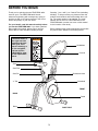
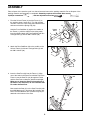
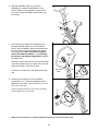
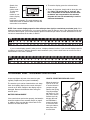
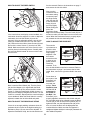
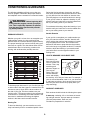
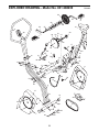
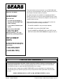
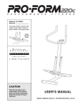
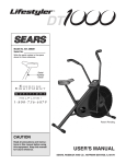
¨
USERÕS MANUAL
Model No. 831.288230
Serial No
The serial number is found in the
location shown below. Write the
serial number in the space above.
Serial
Number
Decal
SEARS, ROEBUCK AND CO.,
HOFFMAN ESTATES, IL 60179
CAUTION
Read all precautions and
instructions in this manual
before using this equipment.
Keep this manual for future
reference.
Visit our website at
www.proform.com
new products, prizes,
fitness tips, and much more!
TABLE OF CONTENTS
IMPORTANT PRECAUTIONS . . . . . . . . . . . . . . . . . . . . . . . . . . . . . . . . . . . . . . . . . . . . . . . . . . . . . . . . . . . . .2
BEFORE YOU BEGIN . . . . . . . . . . . . . . . . . . . . . . . . . . . . . . . . . . . . . . . . . . . . . . . . . . . . . . . . . . . . . . . . . . .3
ASSEMBLY . . . . . . . . . . . . . . . . . . . . . . . . . . . . . . . . . . . . . . . . . . . . . . . . . . . . . . . . . . . . . . . . . . . . . . . . . . .4
HOW TO USE THE EXERCISE CYCLE . . . . . . . . . . . . . . . . . . . . . . . . . . . . . . . . . . . . . . . . . . . . . . . . . . . . . .6
STORAGE AND TROUBLE-SHOOTING . . . . . . . . . . . . . . . . . . . . . . . . . . . . . . . . . . . . . . . . . . . . . . . . . . . . .7
CONDITIONING GUIDELINES . . . . . . . . . . . . . . . . . . . . . . . . . . . . . . . . . . . . . . . . . . . . . . . . . . . . . . . . . . . . .9
PART LIST . . . . . . . . . . . . . . . . . . . . . . . . . . . . . . . . . . . . . . . . . . . . . . . . . . . . . . . . . . . . . . . . . . . . . . . . . . .10
EXPLODED DRAWING . . . . . . . . . . . . . . . . . . . . . . . . . . . . . . . . . . . . . . . . . . . . . . . . . . . . . . . . . . . . . . . . .11
HOW TO ORDER REPLACEMENT PARTS . . . . . . . . . . . . . . . . . . . . . . . . . . . . . . . . . . . . . . . . . . .Back Cover
FULL 90-DAY WARRANTY . . . . . . . . . . . . . . . . . . . . . . . . . . . . . . . . . . . . . . . . . . . . . . . . . . . . . . .Back Cover
IMPORTANT PRECAUTIONS
WARNING:
To reduce the risk of serious injury, read the following important precautions before using the exercise cycle.
8. When adjusting the seat, insert the seat pin
through one of the holes in the seat post
(see the drawing on page 3). Do not insert
the seat pin under the seat post.
1. Read all instructions in this manual before
using the exercise cycle. Use the exercise
cycle only as described.
2. It is the responsibility of the owner to ensure
that all users of the exercise cycle are adequately informed of all precautions.
9. Make sure that the seat pin is inserted into
the front of the frame and the seat post.
Never insert the seat pin into the back of the
frame.
3. Use the exercise cycle indoors, away from
moisture and dust. Place the exercise cycle
on a level surface, with a mat beneath it to
protect the floor or carpet from damage.
10. Always keep your back straight when using
the exercise cycle. Do not arch your back.
11. If you feel pain or dizziness at any time
while exercising, stop immediately and
begin cooling down.
4. Inspect and tighten all parts regularly.
Replace any worn parts immediately.
5. Keep children under the age of 12 and pets
away from the exercise cycle at all times.
12. The exercise cycle is intended for in-home
use only. Do not use the exercise cycle in
any commercial, rental, or institutional
setting.
6. The exercise cycle should not be used by
persons weighing more than 250 pounds.
13. The exercise cycle does not have a freewheel; the pedals will continue to move until
the flywheel stops.
7. Wear appropriate clothing when exercising;
do not wear loose clothing that could become
caught on the exercise cycle. Always wear
athletic shoes for foot protection.
WARNING:
Before beginning this or any exercise program, consult your physician.
This is especially important for persons over the age of 35 or persons with pre-existing health problems. Read all instructions before using. SEARS assumes no responsibility for personal injury or
property damage sustained by or through the use of this product.
2
BEFORE YOU BEGIN
Thank you for selecting the new PROFORM¨ 900L
exercise cycle. The PROFORM 900L blends
advanced engineering with contemporary styling to
provide you with a low-impact workout in the convenience and privacy of your own home.
Saturday, 7 a.m. until 7 p.m. Central Time (excluding
holidays). To help us assist you, please mention the
product model number and serial number when calling. The model number is 831.288230. The serial
number can be found on a decal attached to the
PROFORM 900L (see the front cover of this manual
for the location of the decal).
For your benefit, read this manual carefully before
you use the PROFORM 900L. If you have questions
after reading the manual, please call our toll-free
HELPLINE at 1-800-736-6879, Monday through
Before reading further, please familiarize yourself with
the parts that are labeled in the drawing below.
The decal shown at
the right has been
placed on the exercise cycle. If the
decal is missing, or
if it is not legible,
call our toll-free
HELPLINE to order
a free replacement
decal.
Handlebars
Console
Seat
Seat Post
Seat Pin
Resistance Knob
ÒLÓ Pin
Sideshield
FRONT
BACK
Pedal
Roller
RIGHT SIDE
3
ASSEMBLY
Place all parts of the exercise cycle in a cleared area and remove the packing materials. Do not dispose of the
packing materials until assembly is completed. Assembly requires the included allen wrench
,
a phillips screwdriver
, and two adjustable wrenches
.
1. Pivot the Scissor Frame (3) and the Frame (1) to
the position shown. Insert the ÒLÓ Pin (56) through
one side of Scissor Frame using the indicated holes
and secure it with the Spring Clip (52).
1
56
52
Square
Holes
Hold the Front Stabilizer (2) against the saddle on
the Frame (1), with the square holes facing away
from the saddle. Attach the Front Stabilizer with two
Carriage Bolts (5) and two M8 Locknuts (39).
2
3
5
1
2. Attach the Rear Stabilizer (46) to the saddle on the
Scissor Frame (3) with two Carriage Bolts (5) and
two M8 Locknuts (39).
39
2
3
39
46
5
3. Insert the Seat Post (20) into the Frame (1). Align
one of the holes in the Seat Post with the hole in the
Frame. Insert the Seat Pin (16) through the Frame
and the Seat Post to select the desired seat height.
Make sure to insert the Seat Pin through one of
the holes in the Seat Post; do not insert the Seat
Pin under the Seat Post.
3
21
47
Next, attach the Seat (21) to the Seat Post (20) with
three M8 Washers (47) and three M8 Locknuts (39).
Note: The Seat Washers and Locknuts may be preattached to the bottom of the Seat.
39
16
20
1
4
4. Slide the Handlebar Collars (12) onto the
Handlebars (6). Attach the Handlebars to the
Scissor Frame (3) with eight M5 x 12mm Screws
(19). Next, slide the Handlebar Collars down over
the Screws.
4
6
12
12
19
19
3
5. The Console (48) requires two AA batteries (not
included). Alkaline batteries are recommended.
Refer to the inset drawing. Remove the battery door
from the Console. Press two batteries into the battery compartment. Make sure that the negative
ends of the batteries (marked ÒÐÓ) are touching
the springs in the battery compartment. Reattach
the battery door.
5
Console
Wire
48
Slide the Console (48) onto the console plate. Make
sure that the plastic clip on the back of the Console
snaps into the tab on the console plate.
48
49
Console
Plate
Connect the console wire to the Reed Switch Wire
(49).
Batteries
Battery Door
6. Identify the Left Pedal (8). (The Left Pedal is
marked with an ÒL.Ó) Using an adjustable wrench,
tighten the Left Pedal counterclockwise into the left
arm of the Crank (53).
6
Tighten the Right Pedal (9) (not shown) clockwise
into the Right arm on the Crank.
8
53
3
7. Make sure that all parts are properly tightened before you use the exercise cycle.
5
HOW TO USE THE EXERCISE CYCLE
HOW TO ADJUST THE SEAT
DESCRIPTION OF THE CONSOLE
For effective
exercise, the
Seat (21) should
be at the proper
height. As you
20
21
pedal, there
should be a
16
slight bend in
your knees
when the pedals
1
are in the lowest
position. To
adjust the Seat,
first hold the
Seat and
remove the Seat Pin (16). Align one of the holes in
the Seat Post (20) with the hole in the Frame (1).
Insert the Seat Pin into the Frame and the Seat Post.
Caution: Make sure to insert the Seat Pin through
one of the holes in the Seat Post; do not insert the
Seat Pin under the Seat Post. In addition, make
sure that the Seat Pin is inserted into the front of
the Frame and the Seat Post as shown above.
The console features five modes that provide instant
exercise feedback during your workouts. The modes
are described below.
¥ SpeedÑDisplays
your pedaling
speed, in miles
per hour.
Display
¥ TimeÑDisplays
the elapsed time.
Note: If you stop
pedaling for ten
seconds or
longer, the time
mode will pause
until you resume.
Mode Indicators
¥ DistanceÑ
Displays the total
distance you have pedaled, in miles.
¥ CalorieÑDisplays the approximate number of
Calories you have burned.
HOW TO ADJUST THE PEDALING RESISTANCE
¥ ScanÑDisplays the speed, time, distance, and calorie modes, for 5 seconds each, in a repeating cycle.
To vary the
intensity of your
exercise, the
pedaling resis27
tance can be
adjusted. The
resistance is
controlled with
the Resistance
Knob (27). To
increase the
resistance, turn
the Resistance Knob clockwise; to decrease the resistance, turn the Resistance Knob counterclockwise.
HOW TO OPERATE THE CONSOLE
1. To turn on the power, press the on/reset button or
simply begin pedaling. When the power is turned
on, the entire display will appear for two seconds.
The console will then be ready for operation.
2. Select one of the five modes:
Scan modeÑ
Mode Indicator
When the
power is
turned on, the
scan mode will
automatically
be selected.
One mode
indicator will
show that the scan mode is selected, and a flashing mode indicator will show which mode is currently displayed. Note: If a different mode is selected,
you can select the scan mode again by repeatedly
pressing the mode button.
BATTERY INSTALLATION
Before the console can be operated, two ÒAAÓ batteries must be installed. If you have not installed batteries, see assembly step 5 on page 5.
6
Speed, time,
distance or
calorie modeÑ
To select one
of these
modes for continuous display,
press the
mode button repeatedly. The mode indicators will
show which mode is selected. Make sure that the
scan mode is not selected.
3. To reset the display, press the on/reset button.
4. To turn off the power, simply wait for about four minutes. Note: The monitor has an Òauto-offÓ feature. If the pedals are not moved and the monitor buttons are not pressed for four minutes,
the power will turn off automatically in order to
conserve the batteries.
NOTE: Your console displays speed in either miles per hour (mph) or revolutions per minute (rpm). If the
displayed speed has a decimal point, your console displays speed in miles per hour; if the displayed speed does
not have a decimal point, your console displays speed in revolutions per minute. Use the chart below to convert
one unit of measurement to the other, if desired
If your console displays speed in miles per hour, it displays distance in miles. If your console displays speed in
revolutions per minute, it displays distance in total revolutions (revs). Use the chart below to convert one unit of
measurement to the other, if desired.
STORAGE AND TROUBLE-SHOOTING
Inspect and tighten all parts of the exercise cycle
regularly. Replace any worn parts immediately.
HOW TO STORE THE EXERCISE CYCLE
When the exercise
cycle is not in use,
it can be folded for
compact storage.
Remove the Spring
Clip (52) and then
pull out the ÒLÓ Pin
(56). Next, fold the
exercise cycle by
bringing the seat
and handlebars
toward one another. Store the exercise cycle indoors,
away from moisture and dust.
The exercise cycle can be cleaned with a soft, damp
cloth. Avoid spilling liquid on the console. Keep the
console out of direct sunlight or the display may be
damaged. Remove the batteries when storing the
exercise cycle.
BATTERY REPLACEMENT
If the console does not function properly, the batteries
should be replaced. See assembly step 5 on page 5.
In addition, make sure that the console wire is connected to the reed switch wire.
7
52
56
HOW TO ADJUST THE REED SWITCH
first be removed. Refer to the instructions on page 7
and remove the left side shield.
10
Next, turn the
resistance knob to
38
53
the lowest setting.
Locate and open
the Strap Clamp
15
(38). Grip the end
of the Resistance
Strap (15) and
pull it up slightly.
While holding the
end of the
Resistance Strap,
fully close the Strap Clamp. Turn the Crank (53) for a
moment to make sure that there is not too much resistance. When the Resistance Strap is properly adjusted, reattach the left side shield and pedal.
40
8
40
53
7
If the console does not display correct feedback, the
reed switch should be adjusted. In order to adjust the
reed switch, the Left Side Shield (10) must be
removed. Using an adjustable wrench, turn the Left
Pedal (8) clockwise and remove it from the Crank
(53). Remove the three M4 x 12mm Screws (40) and
the two M4 x 16mm Screws (7) from the Left Side
Shield. Make sure that the arm of the Crank is in the
position shown in the drawing above. Carefully slide
the Left Side Shield forward off the arm of the Crank
and remove it.
HOW TO ADJUST THE DRIVE BELT
The exercise
cycle features a
14
precision drive
belt that must be
kept properly
adjusted. If the
Top View
belt causes
excessive noise
or slips as you
pedal, the belt
should be
checked. To do
this, the side shields must first be removed. Refer to
the instructions on page 7 and remove the left side
shield. Next, remove the right side shield in the same
way.
4
53
7
49
Press down on
the center of the
14
30
Drive Belt (14)
between the
front and rear
pulleys. There
Top View
should be from
1/4Ó to 1/2Ó of
movement in
54
the center of
29
the Belt. If the
Drive Belt (14) is
properly adjusted, reattach the side shields and pedals. If the Belt needs to be adjusted, loosen the Nylon
Locknut (54) on the left side of the Flywheel (29). To
tighten the Belt, turn the Adjustment Nut (30) clockwise; to loosen the Belt, turn the Adjustment Nut
counterclockwise. Make sure that the Flywheel is
straight and tighten the Nylon Locknut (54). Reattach the
side shields and pedals.
Next, locate the Reed Switch (49). Turn the Crank
(53) until the Magnet (4) is aligned with the Reed
Switch. Loosen but do not remove the M4 x 16mm
Screw (7). Slide the Reed Switch slightly closer to or
away from the Magnet. Retighten the Screw. Turn the
Crank for a moment. Repeat until the console displays
correct feedback. When the Reed Switch is correctly
adjusted, reattach the left side shield and pedal.
HOW TO ADJUST THE RESISTANCE STRAP
If there is not enough pedaling resistance when the
resistance knob is turned to the highest setting, the
Resistance Strap (15) may need to be adjusted. To
adjust the Resistance Strap, the left side shield must
8
CONDITIONING GUIDELINES
The following guidelines will help you to plan your
exercise program. Remember that proper nutrition
and adequate rest are essential for successful results.
During the first few minutes of exercise, your body
uses easily accessible carbohydrate calories for energy. Only after the first few minutes of exercise does
your body begin to use stored fat calories for energy.
If your goal is to burn fat, adjust the intensity of your
exercise until your heart rate is near the lowest number in your training zone as you exercise.
WARNING:
Before beginning this
or any exercise program, consult your physician. This is especially important for persons
over the age of 35 or persons with pre-existing health problems.
For maximum fat burning, adjust the intensity of your
exercise until your heart rate is near the middle number in your training zone as you exercise.
Aerobic Exercise
EXERCISE INTENSITY
If your goal is to strengthen your cardiovascular system, your exercise must be Òaerobic.Ó Aerobic exercise is activity that requires large amounts of oxygen
for prolonged periods of time. This increases the
demand on the heart to pump blood to the muscles,
and on the lungs to oxygenate the blood. For aerobic
exercise, adjust the intensity of your exercise until
your heart rate is near the highest number in your
training zone.
Whether your goal is to burn fat or to strengthen your
cardiovascular system, the key to achieving the
desired results is to exercise with the proper intensity.
The proper intensity level can be found by using your
heart rate as a guide. The chart below shows recommended heart rates for fat burning, maximum fat
burning, and cardiovascular (aerobic) exercise.
HOW TO MEASURE YOUR HEART RATE
To measure your
heart rate, first exercise for at least four
minutes. Then, stop
exercising and
place two fingers on
your wrist as
shown. Take a sixsecond heartbeat
count, and multiply
the result by 10 to find your heart rate. For example, if
your six-second heartbeat count is 14, your heart rate
is 140 beats per minute. (A six-second count is used
because your heart rate will drop rapidly when you
stop exercising.)
To find the proper heart rate for you, first find your age
on either side of the chart (ages are rounded off to the
nearest ten years). Next, find the three numbers to
the side of your age. The three numbers are your
Òtraining zone.Ó The lowest number is the recommended heart rate for fat burning; the middle number is the
heart rate for maximum fat burning; the highest
number is the heart rate for aerobic exercise.
WORKOUT GUIDELINES
Each workout should include the following three parts:
A warm-up, consisting of 5 to 10 minutes of stretching and light exercise. A proper warm-up increases
your body temperature, heart rate, and
circulation in preparation for exercise.
Burning Fat
To burn fat effectively, you must exercise at a relatively low intensity level for a sustained period of time.
9
Training zone exercise, consisting of 20 to 30 minutes of exercising with your heart rate in your training
zone. (During the first few weeks of your exercise program, do not keep your heart rate in your training
zone for longer than 20 minutes.)
EXERCISE FREQUENCY
To maintain or improve your condition, plan three workouts each week, with at least one day of rest between
workouts. After a few months of regular exercise, you
may complete up to five workouts each week, if
desired. Caution: Be sure to progress at your own
pace and avoid overdoing it. Incorrect or excessive
training may result in injury to your health.
A cool-down, with 5 to 10 minutes of stretching. This
will increase the flexibility of your muscles and will
help to prevent post-exercise problems.
Remember, the key to success is make exercise a
regular and enjoyable part of your everyday life.
PART LISTÑModel No. 831.288230
Key No. Qty.
1
2
3
4
5
6
7
8
9
10
11
12
13
14
15
16
17
18
19
20
21
22
23
24
25
26
27
28
29
30
1
1
1
1
4
1
5
1
1
1
1
2
4
1
1
1
1
1
8
1
1
1
2
1
1
1
1
1
1
1
Description
R1098A
Key No. Qty.
Frame
Front Stabilizer
Scissor Frame
Magnet
Carriage Bolt
Handlebar
M4 x 16mm Screw
Left Pedal
Right Pedal
Left Side Shield
Right Side Shield
Handlebar Collar
Endcap
Drive Belt
Resistance Strap
Seat Pin
Frame Bushing
Seat Post Bushing
M5 x 12mm Screw
Seat Post
Seat
Large Pulley
Push Nut
Roller Axle
Roller
Bearing Assembly
Resistance Knob
Resistance Control/Cable
Flywheel
M10 Nylon Locknut
31
32
33
34
35
36
37
38
39
40
41
42
43
44
45
46
47
48
49
50
51
52
53
54
55
56
57
58
#
1
2
1
2
2
1
2
1
7
3
1
1
1
4
1
1
3
1
1
1
1
1
1
1
1
1
2
1
1
Description
Adjustment Sleeve
Flywheel Bushing
Flywheel Pulley/Axle
Axle Cap
M4 x 12mm Screw
Scissor Axle
Crank Nut
Strap Clamp
M8 Locknut
M4 x 12mm Screw
Tension Spring
Clamp Screw
Resistance Spring
1/4Ó Washer
Clamp Nut
Rear Stabilizer
M8 Washer
Console
Reed Switch w/Wire
M5 x 16mm Flat Head Screw
M10 Washer
Spring Clip
Crank
1/2-13 UNC Nylon Locknut
Reed Switch Clamp
ÒLÓ Pin
Scissor Frame Spacer
Scissor Frame Sleeve
UserÕs Manual
Note: Ò#Ó refers to a non-illustrated part. Specifications are subject to change without notice. See the back cover
of this manual for information about ordering replacement parts.
10
EXPLODED DRAWINGÑModel No. 831.288230
R1098A
22
53
9
26
4
37
53
21
6
48
33
29 30 51 31
8
47
32
27
17
16
54
35
39
28
12
41
43
45
20
35
7
55
42
13
34
44
19
18
57
58
2
5
57
19
13
56
39
38
36
52
11
1
50
15
34
3
7
10
39
13
49
39
40
7
14
46
5
7
13
23
25
24
23
11
The model number and serial number of your PROFORM¨ 900L
are listed on a decal attached to the frame. See the front cover of
this manual to find the location of the decal.
Model No. 831.288230
All replacement parts are available for immediate purchase or
special order when you visit your nearest SEARS Service Center.
To request service or to order parts by telephone, call the toll-free
numbers listed at the left.
QUESTIONS?
If you find that:
¥ you need help assembling or
operating the PROFORM¨ 900L
¥ a part is missing
¥ or you need to schedule repair
service
When requesting help or service, or ordering parts, please be
prepared to provide the following information:
¥ The MODEL NUMBER of the product (831.288230).
¥ The NAME of the product (PROFORM¨ 900L).
call our toll-free HELPLINE
1-800-736-6879
MondayÐSaturday, 7 amÐ7 pm
Central Time (excluding holidays)
¥ The KEY NUMBER and DESCRIPTION of the PART (see the
PART LIST and the EXPLODED DRAWING on pages 10 and 11).
REPLACEMENT
PARTS
If parts become worn and need to
be replaced, call the following tollfree number
1-800-FON-PART
(1-800-366-7278)
FULL 90 DAY WARRANTY
For 90 days from the date of purchase, if failure occurs due to defect in material or workmanship in this
SEARS BIKE EXERCISER, contact the nearest SEARS Service Center throughout the United States
and SEARS will repair or replace the BIKE EXERCISER, free of charge.
This warranty does not apply when the BIKE EXERCISER is used commercially or for rental purposes.
This warranty gives you specific legal rights, and you may also have other rights which vary from state
to state.
SEARS, ROEBUCK AND CO., DEPT. 817WA, HOFFMAN ESTATES, IL 60179
Part No. 149020 R0400A
Printed in China © 2000 Sears, Roebuck and Co.