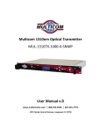
1
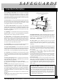
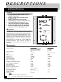
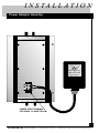
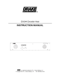
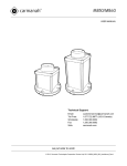
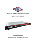
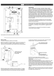
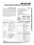
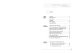
PIDA
Pro Series
OUTP
FORW
ARUT
D
X
M
D
O
PIDA-5
PIDA-7
50
PIDA-1
000 50
O
W
A
R
D
F
PA
T
H
LPF
R
E
T
U
R
N
LPF
FA
0dB
TE-3
ST
:
PA
T
H
L
E
LISTED
69N0
E97199
I/P: AC120V 60Hz
MODEL NO: D12-10-03
O/P: 24V 1250mA
HPF
GAIN
X
T
A
A
HPF
EQ
FA
INPU
FOW
ARDT
0dB
TE-3
ST
RETU
PA
TH RN
A
L
M
HON-KWANG
AHEAD
PLUG IN CLASS 2 TRANSFORMER
AC ADAPTOR
U
Model: MW57-02401250A
® L
WO-W
ISTR
IBUT AY B
ION AROA
MPLDIF
BAN
IERD
A
ID
P
F
GAIN
M
GAAT
FAC
IN TE
NTIO
& SL
TO
RY
FOWTO MIN
IMU
SEOP
T E N
SLOP PATHARD M
E
D T
SP36
/49 MH
LIT
TER z
26
60VA
POW
HzC 1A
ER
INPUT:120V 60Hz 25W
OUTPUT: 26VAC 1.2A
NTSC AUDIO/VIDEO
BROADBAND DISTRIBUTION
AMPLIFIER
Installation
And
Operation
Manual
for PIDA-550, 750 and 1000
Doc. No.OM2964N-1 REV. B
ECO 1769
PICO MACOM, INC. 12500 Foothill Blvd. • Lakeview Terrace, CA 91342 • (818) 897-0028 • (800) 421-6511 • FAX (818) 834-7197
SAFEGUARDS
Important Information
Product Inspection
Inspect the equipment for shipping damage.
Should any damage be discovered, immediately file
a claim with the carrier.
CAUTION
RISK OF ELECTRIC SHOCK
DO NOT OPEN
CAUTION: TO REDUCE THE RISK OF ELECTRIC SHOCK,
DO NOT REMOVE COVER (OR BACK)
NO USER-SERVICEABLE PARTS INSIDE
Important
Safety Instructions
To insure proper installation and operation,
take a moment to read this guide before proceeding
with the installation. If you have any questions or
comments about the PIDA amplifier, please contact
your dealer or have him contact the PICO MACOM
Service Center at the phone numbers on the bottom
of the page.
REFER SEVICING TO QUALIFIED SERVICE PERSONNEL
The lightning flash with arrowhead symbol, within an equilateral
triangle, is intended to alert the user to the presence of uninsulated
"dangerous voltage" within the product's enclosure that may be of
sufficient magnitude to constitute a risk of electric shock to persons.
The exclamation point within an equilateral triangle is intended to
alert the user to the presence of important operating and maintenance (servicing) instructions in the literature accompanying the
appliance.
WARNING: TO REDUCE THE RISK OF FIRE OR ELECTRIC SHOCK, DO NOT EXPOSE
THIS APPLIANCE TO RAIN OR MOISTURE. DO NOT OPEN THE CABINET,
REFER SERVICING TO QUALIFIED PERSONNEL ONLY.
CAUTION: TO PREVENT ELECTRIC SHOCK DO NOT USE THIS (POLARIZED) PLUG
WITH AN EXTENSION CORD RECEPTACLE OR OTHER OUTLET UNLESS
THE BLADES CAN BE FULLY INSERTED TO PREVENT BLADE EXPOSURE.
ATTENCION : POUR PREVENIR LES CHOCS ELECTRIQUES, NE PAS UTILISER CETTE
FICHE POLARISEE AVEC UN PROLONGATEUR, UNE PRISE DE COURANT
OU UNE AUTRE SORTIE DE COURANT, SAUF SI LES LAMES PEUVENT
ETRE INSEREES A FOND SANS ENLAISSER AUCUNE PARTIE A
DECOUVERT.
1. Read Instructions - All safety and operating instructions
should be read before the appliance is operated.
2. Retain Instructions - The safety and operating instructions
should be retained for future reference.
3. Heed Warnings - All warnings on the appliance should be
adhered to.
4. Follow Instructions - All operating and user instructions
should be followed.
5. Cleaning - Unplug this appliance from the wall outlet before
cleaning. Use a damp cloth for cleaning. Do not use liquid
cleaners or aerosol cleansers.
6. Do Not Use Attachments - not recommended by the
manufacturer or they may cause hazards.
7. Water and Moisture - Do not use this product near water for example, near a bathtub, washbowl, kitchen sink, laundry
tub, in a wet basement, or near a swimming pool - and the like.
8. Accessories - Do not place this product on an unstable cart,
stand, tripod, bracket, or table. The product may fall, causing
serious injury to a child or adult, and serious damage to the
appliance.
9. Ventilation - This video product should never be placed near
or over a radiator or heat register. This video product should not
be placed in a built-in installation such as a bookcase or rack
unless proper ventilation is provided or the manufacturer’s
instructions have been adhered to. Any slots or opening in the
cabinet are provided for ventilation. To ensure reliable operation of the video product and to protect it from overheating, these
openings must not be blocked or covered. The openings should
never be blocked by placing the product on a bed, sofa, rug, or
other similar surface.
1
PICO MACOM, INC. 12500 Foothill Blvd. • Lakeview Terrace, CA 91342 • (818) 897-0028 • (800) 421-6511 • FAX (818) 834-7197
SAFEGUARDS
Important Information
EXAMPLE OF ANTENNA GROUNDING ACCORDING TO
10. Grounding or Polarization - This video product is equipped
with either a three prong plug for 120 Vac use. It is to be
inserted into only the type of receptacle for which they specifically designed . Do not cut off the round grounding pin in order
to be able to fit into a two prong receptacle as this could cause
injury and will void the warranty.
11. Power Sources - This product should be operated only from
the type of power source indicated on the marking label. If you
are not sure of the type of power supplied to your home, consult
your appliance dealer or local power company.
12. Power-cord Protection - Power-supply cords should be
routed so they are not likely to be walked on or pinched by items
placed upon or against them. Pay particular attention to cords
and plugs, convenience receptacles, and the point where they
exit from the appliance.
13. Lightning - For added protection for this product during a
lightning storm, or when it is left unattended and unused for
long periods of time, unplug it from the wall outlet.
14. Power Lines - An outside antenna system should not be
located in the vicinity of overhead power lines, other electric
light or power circuits, where it can fall into such power lines or
circuits. When installing an outside antenna system, extreme
care should be taken to keep from touching such power lines or
circuits as contact with them may be fatal.
15. Overloading - Do not overload wall outlets and extension
cords as this can result in risk of fire or electric shock.
16. Object and Liquid Entry - Never push objects of any kind
into this product through openings as they may touch dangerous
voltage points or short-out parts that could result in a fire or
electric shock. Never spill liquid of any kind on the product.
17. Servicing - Do not attempt to service this product yourself
as opening or removing covers may expose you to dangerous
voltage or other hazards. Refer all servicing to qualified service
personnel.
18. Damage Requiring Service - Unplug this product from the
wall outlet and refer servicing to qualified service personnel
under the following conditions:
a. When the power-supply cord or plug is damaged.
b. If liquid has been spilled, or objects have fallen into the
product.
c. If the product has been exposed to rain or water.
d. If the product does not operate normally by following the
operating instruction. Adjust only those controls that are
covered by the operating instructions. An improper adjustment
may result in damage and will often require extensive work by
a qualified technician to restore the product to its normal
operation.
e. If the product has been dropped or the cabinet has been
damaged.
f. When the product exhibits a distinct change in performance
- this indicates a need for service.
NATIONAL ELECTRICAL CODE INSTRUCTIONS CONTAINED
IN ARTICLE 810 - "RADIO AND TELEVISION
EQUIPMENT"
POW
ER
LINE
S
GROUND CLAMP
SERVICE ENTRANCE
CONDUCTORS
STANDOFF
INSULATORS b
MAST
SERVICE
ENTRANCE
EQUIPMENT
ANTENNA
LEAD-IN WIRE
GROU
ND C
LAMPS
POWER SERVICE GROUNDING
ELECTRODE SYSTEM
(e.g. interior metal water pipe)
ANTENNA
c
DISCHARGE UNIT
TO EXTERNAL ANTENNA
TERMINALS OF PRODUCT
BONDING JUMPER
d
GROUND WIRE
GROUND CLAMPS
OPTIONAL ANTENNA GROUNDING ELECTRODE
DRIVEN 8 FEET (2.44M) INTO THE EARTH
IF REQUIRED BY LOCAL CODES. SEE NEC
SECTION 810 - 21(f).
19. Replacement Parts - When replacement parts are required,
be sure the service technician has used replacement parts specified by the manufacturer or have the same characteristics as the
original parts. Unauthorized substitutes may result in fire,
electric shock or other hazards.
20. Safety Check - Upon completion of any service or repairs
to this product, ask the service technician to perform safety
checks to determine that the product is in proper operating
conditions.
21. Outdoor Antenna Grounding - Before attempting to install
this product, be sure the antenna or cable system is grounded so
as to provide some protection against voltage surges and built-up
static charges.
a. Use No.10 AWG (5.3mm ) copper, No.8 AWG (8.4mm
(aluminum, No.7 AWG (10mm ) copper-clad steel or bronze
wire or larger, as ground wire.
b. Secure antenna lead-in and ground wires to house with standoff insulators spaced from 4 feet (1.22m) to 6 feet (1.83m) apart.
c. Mount antenna discharge unit as close as possible to where
lead-in enters house.
d. A driven rod may be used as the grounding electrode where
other types of electrode systems do not exist. Refer to the
National Electrical Code, ANSI/NFPA 70-1984 for information.
e. Use jumper wire not smaller than No.6 AWG (13.3mm )
copper or equivalent, when a separate antenna grounding electrode is used.
NOTE TO THE CATV SYSTEM INSTALLER:
THIS REMINDER IS PROVIDED TO CALL THE CATV SYSTEM INSTALLER’S ATTENTION TO ARTICLE 820 - 40 OF THE
NEC THAT PROVIDES GUIDELINES FOR PROPER GROUNDING AND, IN PARTICULAR, SPECIFIES THAT THE CABLE
GROUND SHALL BE CONNECTED TO THE GROUNDING
SYSTEM OF THE BUILDING, AS CLOSE TO THE POINT OF
CABLE ENTRY AS PRACTICAL.
2
PICO MACOM, INC. 12500 Foothill Blvd. • Lakeview Terrace, CA 91342 • (818) 897-0028 • (800) 421-6511 • FAX (818) 834-7197
DESCRIPTIONS
and Specifications
Features
•
+
•
•
+
•
•
•
+
•
Several models available in 1000, 750 and
550MHz bandwidths
Built-in variable slope and gain controls
for foward path
Built-in gain control for reverse path
Optional plug-in equalizers and attenuators
Dual push-pull hybrid modules for low
distortion, high input and output capability
External U.L approved 26Vac power supply
Input and output test ports for monitoring
signal levels without disturbing service.
OUTPUT
FORWARD
-30dB
TEST
GAIN
MAX
RETURN
PATH
ATTENTION
PIDA
GAIN & SLOPE
FACTORY SET
TO MINIMUM
FOWARD
PATH
FOWARD PATH
TILT
TWO-WAY BROADBAND
DISTRIBUTION AMPLIFIER
SLOPE
Description
FLAT
+
+
GAIN
MODEL:
PIDA-550
PIDA-750
PIDA-1000
MAX
LPF
HPF
LPF
RETURN PATH
FOWARD PATH
HPF
EQ
FA
FA
INPUT
FOWARD
-30dB
TEST
26VAC 1A
60Hz
POWER
+
+
+
The PIDA series of broadband distribution amplifiers
are high quality push-pull amplifiers producing signal
with extremely low distortion and high output. These
amplifiers are designed for RF distribution systems for
hospitals, schools, apartment complexes, hotels and
similar applications. It can also be used as a headend
launch amplifier in conjunction with the PHC-12U
headend combiner. The enclosure is made of
aluminum to assure reliable heat sinking and corrosion
resistance.
Specifications
Frequency Range:
3
Foward Path
Return Path
PIDA-1000: 50-1000MHz
PIDA-750: 50-750MHz
PIDA-550: 50-550MHz
110
±0.75dB
30dB
8.5dB
+40dBmV
-30±2dB
10dB
8dB
-53dB
-56dB
-54dB
-70dB
75 ohms
16dB
-20 to +60 deg C
26Vac, 60
7.25 x 3.25 x 10.25
2
Push-Pull
5-36MHz
5-36MHz
5-36MHz
3
±0.5 ref to 1dB tilt
20dB
6dB
+42dBmV
------18dB
-------60dB
-60dB
-60dB
-65dB
75 ohms
16dB
-------------------------------
Channel Loading:
Flatness:
Gain:
Noise Figure (a):
Output Level:
Test Port Level:
Gain Control Range:
Slope Control Range:
Composite Triple Beat-CTB (b):
Composite Second Order-CSO (b):
Cross Modulation-XMOD (b):
Hum Modulation:
Impedance-All Ports:
Return Loss-Input and Output:
Operating Temperature:
Power Supply (adapter):
Size (approximate):
Number of Hybrids:
Hybrid type:
Notes:
a.
measured at full gain with 0dB slope
b.
at specified channel loading at rated output capacity
PICO MACOM, INC. 12500 Foothill Blvd. • Lakeview Terrace, CA 91342 • (818) 897-0028 • (800) 421-6511 • FAX (818) 834-7197
DESCRIPTIONS
PCB Plug-In Module and Jumper Locations
RETURN PATH INPUT
FOWARD PATH OUTPUT
-30dB OUTPUT
TEST POINT
GAIN CONTROL
(RETURN PATH)
REMOVE JUMPERS W6 AND
W5 AND INSERT JUMPER
BETWEEN THESE TWO POINTS
FOR PASSIVE RETURN PATH
JUMPERS W5 AND W6
INSERTED FOR ACTIVE
RETURN PATH
W5
SLOPE CONTROL
(FOWARD PATH)
W10
W6
EQUALIZER
W3
PLUG-IN LOCATION
FOR ATTENUATOR*
(RETURN PATH)
PIDA 550/750/1000
W8
GAIN CONTROL
(FOWARD PATH)
W2
FOWARD
ATTENUATOR
PLUG-IN LOCATION
FOR ATTENUATOR*
(FORWARD PATH)
PLUG-IN LOCATION
FOR EQUALIZER*
(FORWARD PATH)
-30dB INPUT
TEST POINT
FOWARD PATH INPUT
RETURN PATH OUTPUT
*NOTE:
PLUG-IN EQUALIZERS AND ATTENUATORS ARE OPTIONAL.
IF PLUG-INS ARE TO BE USED REMOVE JUMPER WIRE AT
APPROPRIATE LOCATION AND INSERT PLUG-IN.
4
PICO MACOM, INC. 12500 Foothill Blvd. • Lakeview Terrace, CA 91342 • (818) 897-0028 • (800) 421-6511 • FAX (818) 834-7197
DESCRIPTIONS
Block Diagram
RF OUTPUT
RETURN PATH INPUT
TEST PORT
(-30dB)
HYBRID AMP
2
ATT.
49 MHz 36 MHz
HPF
LPF
FLAT
SLOPE CONTROL
CIRCUIT
FULL
GAIN CONTROL
CIRCUIT
P4
GAIN CONTROL
CIRCUIT
HYBRID AMP
1
PASSIVE RETURN
FULL
J2
P3
J3
FREQUENCY OFFSETS - FCC (U.S.A.)
P2
J1
W3
P1
W8
W2
49 MHz 36 MHz
HPF
LPF
ATT.
RF INPUT
TEST PORT
RETURN PATH OUTPUT
(-30dB)
NOTES:
1. FOR PASSIVE RETURN, CONNECT J3 TO P1 AND P4.
2. FOR ACTIVE RETURN, CONNECT J1 TO P1 AND P2 ANDJ2 TO P3 AND P4
3. PLUG-IN EQUALIZERS AND ATTENUATORS ARE OPTIONAL. IF PLUG-INS ARE TO BE USED
REMOVE JUMPER WIRE AT APPROPRIATE LOCATION AND INSERT PLUG-IN
5
PICO MACOM, INC. 12500 Foothill Blvd. • Lakeview Terrace, CA 91342 • (818) 897-0028 • (800) 421-6511 • FAX (818) 834-7197
I N S TA L L AT I O N
Power Adaptor Hook-Up
HON-KWANG
AHEAD
PLUG IN CLASS 2 TRANSFORMER
AC ADAPTOR
U
Model: MW57-02401250A
® L
LISTED
69N0
E97199
I/P: AC120V 60Hz
MODEL NO: D12-10-03
O/P: 24V 1250mA
INPUT:120V 60Hz 25W
OUTPUT: 26VDC 1.0A
POWER STRIP TERMINAL
FOR 26VAC, 1A ADAPTOR
6
PICO MACOM, INC. 12500 Foothill Blvd. • Lakeview Terrace, CA 91342 • (818) 897-0028 • (800) 421-6511 • FAX (818) 834-7197
I N S TA L L AT I O N
Distribution
T
he output levels of the modulator should be the same as the output of the off-air strip amplifiers. The M860
modulators are usually combined with either the SP860 signal processor, LBS/MBS/FMS/UBS series strip
amplifiers. Two methods are suggested to combine strip amplifier, modulator and processor outputs which
are then amplified with the PIDA distribution amplifier serving as a launchamp.
T
he PHC-12U twelve channel passive headend combiner consists of two rows of directional couplers
combined by a hybrid splitter. The directional coupler combining provides high isolation (40 dB) between
the inputs. Normally, the odd channels are combined on one row while even channels are combined on the
other row of directional couplers. The combiner loss is 16 dB per channel.
V
A
M860
+52dBmV
Ch. 2
PHC-12U
-16dB
RF
IN
+10dBmV
SP860
+52dBmV
Ch. 3
+36dBmV
6dB PAD
PIDA-*
+60dBmV
ATTENUATOR PAD
RF
IN
+14dBmV
+10dBmV
*BS
+52dBmV
Ch. 4
Another method of combining signals uses three hybrid splitters per headend rack. The odd channels are
combined in one splitter, the even channels in another splitter and the two splitters are combined to a single
output with a third splitter. Each rack is then combined with a final splitter prior to the PIDA amplifier.
NOTE :
*
Denotes either LBS, MBS, HBS or FMS model numbers.
Ch. 2
V
A
M860S
+60dBmV
+45dBmV
Ch. 4
RF
IN
EVEN CHANNELS
+10dBmV
SP860
+52dBmV
+38dBmV
Ch. 3
RF
IN
+14dBmV
+10dBmV
*BS
+52dBmV
8dB PAD
PIDA-*
+60dBmv
ATTENUATOR PAD
+45dBmV
ODD CHANNELS
*PIDA-550, 750, 1000
7
16
PICO MACOM, INC. 12500 Foothill Blvd. • Lakeview Terrace, CA 91342 • (818) 897-0028 • (800) 421-6511 • FAX (818) 834-7197
WARRANTY
Five Year Limited Warranty*
P
ico Macom, Inc. warrants to the original
purchaser this product shall be free of
defects in material
and craftsmanship
with only the limitations or exclusions
set out below.
During the warranty period Pico
Macom, Inc. or an authorized Pico
Macom service facility will provide,
free of charge, the parts and labor
necessary to correct defects in material and workmanship.
Warranty Duration
This warranty shall terminate five
years* from the original date of purchase of the product or at a time the
product is:
1. Misused or damaged due to
neglect or improper installation
2. Modified
3. Repaired by someone other
than the warrantor
4. Sold by the original purchaser
Statement of Remedy
To obtain such a warranty service,
contact the salesperson where the product was obtained or contact Pico Macom,
Inc at the address listed at bottom of page
. You will be issued a Return Authorization (RA) number which will be used to
track your product.
Be prepared to provide:
1. The model number and channel
number of the product
2. The date of purchase
3. A specific identification of the
problem
Deliver the products to Pico Macom,
Inc. or ship the products in the original
packing material at the address at the
bottom of the page. Include satisfactory
evidence of the date of purchase.
Products will not be accepted by Pico
Macom, Inc. without the RA number
clearly indicated on the shipping label.
The foregoing constitutes the Pico
Macom, Inc. entire obligation with respect to this product and the original
purchaser and any user or owner shall
have no other remedy and no claim for
incidental or consequential damages.
This warranty gives you specific legal rights, and you also have rights which
vary from state to state. (U.S.A.)
*One year limited warranty on
product sold outside the U.S.A.
8
PICO MACOM, INC. 12500 Foothill Blvd. • Lakeview Terrace, CA 91342 • (818) 897-0028 • (800) 421-6511 • FAX (818) 834-7197
NOTES
PICO MACOM, INC. 12500 Foothill Blvd. • Lakeview Terrace, CA 91342 • (818) 897-0028 • (800) 421-6511 • FAX (818) 834-7197
NOTES
PICO MACOM, INC. 12500 Foothill Blvd. • Lakeview Terrace, CA 91342 • (818) 897-0028 • (800) 421-6511 • FAX (818) 834-7197
PICO MACOM, INC. 12500 Foothill Blvd. • Lakeview Terrace, CA 91342 • (818) 897-0028 • (800) 421-6511 • FAX (818) 834-7197