1
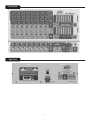
PV™i 8B+
350-Watt, 8-Channel Mixer Amplifier
Operating
Manual
www.peavey.com
Intended to alert the user to the presence of uninsulated “dangerous voltage” within the product’s
enclosure that may be of sufficient magnitude to constitute a risk of electric shock to persons.
Intended to alert the user of the presence of important operating and maintenance (servicing)
instructions in the literature accompanying the product.
CAUTION: Risk of electrical shock — DO NOT OPEN!
CAUTION: To reduce the risk of electric shock, do not remove cover. No user serviceable parts inside.
Refer servicing to qualified service personnel.
WARNING: To prevent electrical shock or fire hazard, this apparatus should not be exposed to rain or
moisture‚ and objects filled with liquids‚ such as vases‚ should not be placed on this apparatus. Before
using this apparatus‚ read the operating guide for further warnings.
Este símbolo tiene el propósito, de alertar al usuario de la presencia de “(voltaje) peligroso” sin
aislamiento dentro de la caja del producto y que puede tener una magnitud suficiente como para
constituir riesgo de descarga eléctrica.
Este símbolo tiene el propósito de alertar al usario de la presencia de instruccones importantes sobre la
operación y mantenimiento en la información que viene con el producto.
PRECAUCION: Riesgo de descarga eléctrica ¡NO ABRIR!
PRECAUCION: Para disminuír el riesgo de descarga eléctrica, no abra la cubierta. No hay piezas útiles
dentro. Deje todo mantenimiento en manos del personal técnico cualificado.
ADVERTENCIA: Para prevenir choque electrico o riesgo de incendios, este aparato no se debe exponer a
la lluvia o a la humedad. Los objetos llenos de liquidos, como los floreros, no se deben colocar encima
de este aparato. Antes de usar este aparato, lea la guia de funcionamiento para otras advertencias.
Ce symbole est utilisé dans ce manuel pour indiquer à l’utilisateur la présence d’une tension dangereuse
pouvant être d’amplitude suffisante pour constituer un risque de choc électrique.
Ce symbole est utilisé dans ce manuel pour indiquer à l’utilisateur qu’il ou qu’elle trouvera d’importantes
instructions concernant l’utilisation et l’entretien de l’appareil dans le paragraphe signalé.
ATTENTION: Risques de choc électrique — NE PAS OUVRIR!
ATTENTION: Afin de réduire le risque de choc électrique, ne pas enlever le couvercle. Il ne se trouve
à l’intérieur aucune pièce pouvant être reparée par l’utilisateur. Confiez I’entretien et la réparation de
l’appareil à un réparateur Peavey agréé.
AVIS: Dans le but de reduire les risques d’incendie ou de decharge electrique, cet appareil ne doit
pas etre expose a la pluie ou a l’humidite et aucun objet rempli de liquide, tel qu’un vase, ne doit
etre pose sur celui-ci. Avant d’utiliser de cet appareil, lisez attentivement le guide fonctionnant pour
avertissements supplémentaires.
Dieses Symbol soll den Anwender vor unisolierten gefährlichen Spannungen innerhalb des Gehäuses
warnen, die von Ausreichender Stärke sind, um einen elektrischen Schlag verursachen zu können.
Dieses Symbol soll den Benutzer auf wichtige Instruktionen in der Bedienungsanleitung aufmerksam
machen, die Handhabung und Wartung des Produkts betreffen.
VORSICHT: Risiko — Elektrischer Schlag! Nicht öffnen!
VORSICHT: Um das Risiko eines elektrischen Schlages zu vermeiden, nicht die Abdeckung enfernen.
Es befinden sich keine Teile darin, die vom Anwender repariert werden könnten. Reparaturen nur von
qualifiziertem Fachpersonal durchführen lassen.
WARNUNG: Um elektrischen Schlag oder Brandgefahr zu verhindern, sollte dieser Apparat nicht
Regen oder Feuchtigkeit ausgesetzt werden und Gegenstände mit Flüssigkeiten gefuellt, wie Vasen,
nicht auf diesen Apparat gesetzt werden. Bevor dieser Apparat verwendet wird, lesen Sie bitte den
Funktionsführer für weitere Warnungen.
2
IMPORTANT SAFETY INSTRUCTIONS
WARNING: When using electrical products, basic cautions should always be followed, including the following:
1.
2.
3.
4.
5.
6.
7.
8.
9.
10.
11.
12.
13.
14.
15.
16.
17.
18.
19.
Read these instructions.
Keep these instructions.
Heed all warnings.
Follow all instructions.
Do not use this apparatus near water.
Clean only with a dry cloth.
Do not block any of the ventilation openings. Install in accordance with manufacturer’s instructions.
Do not install near any heat sources such as radiators, heat registers, stoves or other apparatus (including amplifiers)
that produce heat.
Do not defeat the safety purpose of the polarized or grounding-type plug. A polarized plug has two blades with one
wider than the other. A grounding type plug has two blades and a third grounding plug. The wide blade or third prong is
provided for your safety. If the provided plug does not fit into your outlet, consult an electrician for replacement of the
obsolete outlet.
Protect the power cord from being walked on or pinched, particularly at plugs, convenience receptacles, and the point
they exit from the apparatus.
Only use attachments/accessories provided by the manufacturer.
Use only with a cart, stand, tripod, bracket, or table specified by the manufacturer, or sold with the apparatus. When a
cart is used, use caution when moving the cart/apparatus combination to avoid injury from tip-over.
Unplug this apparatus during lightning storms or when unused for long periods of time.
Refer all servicing to qualified service personnel. Servicing is required when the apparatus has been damaged in any
way, such as power-supply cord or plug is damaged, liquid has been spilled or objects have fallen into the apparatus,
the apparatus has been exposed to rain or moisture, does not operate normally, or has been dropped.
Never break off the ground pin. Write for our free booklet “Shock Hazard and Grounding.” Connect only to a power
supply of the type marked on the unit adjacent to the power supply cord.
If this product is to be mounted in an equipment rack, rear support should be provided.
Note for UK only: If the colors of the wires in the mains lead of this unit do not correspond with the terminals in your
plug‚ proceed as follows:
a) The wire that is colored green and yellow must be connected to the terminal that is marked by the letter E‚ the earth
symbol‚ colored green or colored green and yellow.
b) The wire that is colored blue must be connected to the terminal that is marked with the letter N or the color black.
c) The wire that is colored brown must be connected to the terminal that is marked with the letter L or the color red.
This electrical apparatus should not be exposed to dripping or splashing and care should be taken not to place objects
containing liquids, such as vases, upon the apparatus.
Exposure to extremely high noise levels may cause a permanent hearing loss. Individuals vary considerably in susceptibility to noise-induced hearing loss, but nearly everyone will lose some hearing if exposed to sufficiently intense noise
for a sufficient time. The U.S. Government’s Occupational Safety and Health Administration (OSHA) has specified the
following permissible noise level exposures:
Duration Per Day In Hours
8
6
4
3
2
1 1⁄2
1
1⁄2
1⁄4 or less
Sound Level dBA, Slow Response
90
92
95
97
100
102
105
110
115
According to OSHA, any exposure in excess of the above permissible limits could result in some hearing loss. Ear plugs or protectors to
the ear canals or over the ears must be worn when operating this amplification system in order to prevent a permanent hearing loss, if
exposure is in excess of the limits as set forth above. To ensure against potentially dangerous exposure to high sound pressure levels, it is
recommended that all persons exposed to equipment capable of producing high sound pressure levels such as this amplification system be
protected by hearing protectors while this unit is in operation.
SAVE THESE INSTRUCTIONS!
INSTRUCCIONES IMPORTANTES PARA SU SEGURIDAD
CUIDADO: Cuando use productos electrónicos, debe tomar precauciones básicas, incluyendo las siguientes:
1.
Lea estas instrucciones.
2.
3.
4.
5.
6.
7.
8.
9.
10.
11.
12.
13. 14. 15. 16.
17. 18.
19.
Guarde estas instrucciones.
Haga caso de todos los consejos.
Siga todas las instrucciones.
No usar este aparato cerca del agua.
Limpiar solamente con una tela seca.
No bloquear ninguna de las salidas de ventilación. Instalar de acuerdo a las instrucciones del fabricante.
No instalar cerca de ninguna fuente de calor como radiadores, estufas, hornos u otros aparatos (incluyendo amplificadores)
que produzcan calor.
No retire la patilla protectora del enchufe polarizado o de tipo “a Tierra”. Un enchufe polarizado tiene dos puntas, una de
ellas más ancha que la otra. Un enchufe de tipo “a Tierra” tiene dos puntas y una tercera “a Tierra”. La punta ancha (la
tercera ) se proporciona para su seguridad. Si el enchufe proporcionado no encaja en su enchufe de red, consulte a un
electricista para que reemplaze su enchufe obsoleto.
Proteja el cable de alimentación para que no sea pisado o pinchado, particularmente en los enchufes, huecos, y los puntos
que salen del aparato.
Usar solamente añadidos/accesorios proporcionados por el fabricante.
Usar solamente un carro, pie, trípode, o soporte especificado por el fabricante, o vendido junto al aparato. Cuando se use
un carro, tenga cuidado al mover el conjunto carro/aparato para evitar que se dañe en un vuelco. No suspenda esta caja de
ninguna manera.
Desenchufe este aparato durante tormentas o cuando no sea usado durante largos periodos de tiempo.
Para cualquier reparación, acuda a personal de servicio cualificado. Se requieren reparaciones cuando el aparato ha sido
dañado de alguna manera, como cuando el cable de alimentación o el enchufe se han dañado, algún líquido ha sido
derramado o algún objeto ha caído dentro del aparato, el aparato ha sido expuesto a la lluvia o la humedad, no funciona de
manera normal, o ha sufrido una caída.
Nunca retire la patilla de Tierra.Escríbanos para obtener nuestro folleto gratuito “Shock Hazard and Grounding” (“Peligro
de Electrocución y Toma a Tierra”). Conecte el aparato sólo a una fuente de alimentación del tipo marcado al lado del cable
de alimentación.
Si este producto va a ser enracado con más equipo, use algún tipo de apoyo trasero.
Nota para el Reino Unido solamente: Si los colores de los cables en el enchufe principal de esta unidad no corresponden
con los terminales en su enchufe‚ proceda de la siguiente manera:
a) El cable de color verde y azul debe ser conectado al terminal que está marcado con la letra E‚ el símbolo de Tierra
(earth)‚ coloreado en verde o en verde y amarillo.
b) El cable coloreado en azul debe ser conectado al terminal que está marcado con la letra N o el color negro.
c) El cable coloreado en marrón debe ser conectado al terminal que está marcado con la letra L o el color rojo.
Este aparato eléctrico no debe ser sometido a ningún tipo de goteo o salpicadura y se debe tener cuidado para no poner
objetos que contengan líquidos, como vasos, sobre el aparato.
La exposición a altos niveles de ruido puede causar una pérdida permanente en la audición. La susceptibilidad a la pérdida
de audición provocada por el ruido varía según la persona, pero casi todo el mundo perderá algo de audición si se expone
a un nivel de ruido suficientemante intenso durante un tiempo determinado. El Departamento para la Salud y para la
Seguridad del Gobierno de los Estados Unidos (OSHA) ha especificado las siguientes exposiciones al ruido permisibles:
Duración por Día en Horas
8
6
4
3
2
1 1⁄2
1
1
⁄2
1
⁄4 o menos
Nivel de Sonido dBA, Respuesta Lenta
90
92
95
97
100
102
105
110
115
De acuerdo al OSHA, cualquier exposición que exceda los límites arriba indicados puede producir algún tipo de pérdida en la audición.
Protectores para los canales auditivos o tapones para los oídos deben ser usados cuando se opere con este sistema de sonido para prevenir una pérdida permanente en la audición, si la exposición excede los límites indicados más arriba. Para protegerse de una exposición a
altos niveles de sonido potencialmente peligrosa, se recomienda que todas las personas expuestas a equipamiento capaz de producir altos
niveles de presión sonora, tales como este sistema de amplificación, se encuentren protegidas por protectores auditivos mientras esta unidad esté operando.
GUARDE ESTAS INSTRUCCIONES!
ENGLISH
PV™i 8B+
350-Watt, 8-Channel Mixer Amplifier
The PVi 8B+ powered mixer is easy to use and transport, and is designed with the latest Peavey technology. Constructed with a
rugged metal structure, wood cabinet, vinyl surface and protective corners, the PVi 8B+ is the ideal powered mixer.
From packaging to quality control, we produce a product of maximum quality and efficiency with the same specifications you
see on other, more expensive powered mixers.
Please read this guide carefully to ensure your personal safety as well as the safety of your equipment.
Features
◆ 350 watts into 4-ohm (2 x 8 ohm) speakers
◆ 8 Balanced microphone and line inputs
◆ Tape/CD inputs
◆ Reverb level control on each channel
◆ Line Out for connection to external amplifiers
◆ Monitor output for connection to external amplifiers
◆ Return input for connection of external effects processors
◆ Record Out for taping
◆ RF interference protection on all inputs
◆ Switchable 48 volt phantom power for support of electret microphones
◆ Footswitch jack for enable/disable effects
◆ Effects bus output for connection to external effects processing
Front Panel
Rear Panel
Front Panel
(1) 3-PIN LOW-IMPEDANCE MICROPHONE INPUT
This input is for typical balanced, low-impedance microphones. It will automatically provide
phantom power (15V) for condenser mics or active direct boxes. This has an input impedance
of 1k ohms. The connector is wired as: Pin 1=shield; Pin 2=positive (hot); Pin 3=negative
(cold).
(2) 1/4" LINE/HIGH-IMPEDANCE INPUT
This input may be used as either a high-impedance microphone input or for line-level devices such
as a cassette player, CD player, video projector or laptop. This will also allow connection from an
electric guitar, bass or keyboard. It is a two-conductor input with an impedance of 10k ohms.
2
1
5
(3) PAD
Decreases input sensitivity 20 dB to compensate for high-amplitude input sources.
6
(4) MAIN CONTROL
The main control for each channel sends the signal to the master mix bus. Typical operation is
between 4 and 8 (dependent upon the input devices) but should be lower than the master level.
Please remember that this acts like a preamp, so if you are using a device that has a volume output
control (i.e.: a tape or CD player) you will need to do some level matching by adjusting the main
controls on each unit.
7
(5) HIGH TONE CONTROL
This is used to adjust the overall tone of the individual inputs. Since it is a cut or boost control (+/-15
dB), it will add or diminish presence frequencies in the sound beginning at 8 kHz.
9
8
4
(6) MID TONE CONTROL
This is used to adjust the overall tone of the individual inputs. Since it is a cut or boost control (+/-12
db), it will add or diminish presence frequencies in the sound beginning at 2.5 kHz.
3
(7) LOW TONE CONTROL
This is used to adjust the overall tone of the individual inputs. Since it is a cut or boost control (+/-15 dB),
it will add or diminish bass frequencies in the sound beginning at 100 Hz.
(8) EFFECTS CONTROL
11
This is used as a send control to the effects bus. It controls the amount of reverberation added to
the input signals.
11a
(9) MONITOR LEVEL
This controls the overall volume level of the entire amplifier. Typical operation is between 4 and 8. 10
(10) EFFECTS ECHO
This controls the level of the echo and delay that is added back to the master mix.
13
(11) DIGITAL EFFECTS
LED digital display of the currently selected Digital Effect.
(11a) DIGITAL EFFECTS SELECT
This controls the character of the reverb that is added back to the master mix. Each Digital Effect
selected is analogous with changing the rate at which the reverb echo decays.
(12) EFFECTS OUT
This sends the effects to the Effects Out Jack (15).
14
12
(13) EFFECTS SWITCH
This push button switch enables/disables effects.
(14) PHANTOM POWER SWITCH
This switch allows 48 volt phantom power for support of electret microphones.
(15) EFFECTS OUT JACK
Level of effects controlled by Effects Switch (12).
(16) FOOTSWITCH JACK
This jack provides the connection of the optional remote footswitch. Footswitch is used to enable/
disable reverb effects.
16
15
Front Panel
(17) MONITOR EQ
This is the 7-band EQ with level meter.
17
(18) EFFECTS RETURN/MONITOR
This controls the level of effects applied to the monitors.
(19) MONITOR MIX LEVEL
This controls the monitor output level at the Monitor
Output Jack (29).
18
(20) MAIN EQ
These are used to adjust the overall EQ of the master mix.
Since these cover seven frequency bands (+/-12 dB), they
will add or diminish the level of the sound at the indicated
frequencies, spread across approximately one octave of
frequency range. Most situations should require using no
more than three controls simultaneously. Do not boost
or cut all five at the same time. Excessive boosting will
increase the probability of encountering feedback.
19
20
22
21
(21) EFFECTs RETURN/MAIN
This controls the level of effects applied to the mains.
(22) main level
This controls the main output level.
25
23
28
30
31
26
31
27
(23) AUX 1
This is the AUX input to the main mix using the AUX Input Jack (24).
(24) AUX Input jack
This is the AUX input to main mix with levels controlled by AUX 1 (23).
(25) Tape input
This controls the level of the playback inputs (RCA jacks).
32
24
29
(26) TAPE IN (L/R)
These RCA jacks are for connecting a cassette deck, CD player or other line-level source.
(27) TAPE OUT (L/R)
These RCA output jacks are primarily intended for connecting a tape deck, MP3 player, or other device for the
purpose of recording from the mixer. Both channels are summed into mono for compatibility. The signals are
taken pre-master section, meaning that they are without reverb or the master tone section, and do not include
the Tape-In signal. If you wish to record with the reverb and Tape In signals, use the 1/4" line output (2) with the
proper cable.
(28) monitor output jack
1/4" line-level output of monitor mix, controlled by Monitor EQ (17).
(29) main output jack
1/4" line-level output of main mix, controlled by Mains EQ (20).
(30) power led
Illuminates when power is supplied to the unit.
(31) limiter indicators
Red LED illuminates when unit approaches peak limit.
(32) amplifier function switch
3-way switch:
Top position: MAIN/MONITOR: sends the main mix to mains via Speaker Outputs (1) on rear panel and the
monitor mix to monitors via Monitor Output (3) on rear panel
Mid position: MAIN/MAIN: sends the main mix to mains only via Speaker Outputs (1) and (3) on rear panel
Low position: BRIDGE/MAIN: sends the main mix to mains via Bridged Output (2) on rear panel
NOTE: In the BRIDGE/MAIN mode the monitors are disabled.
Rear Panel
5
4
3
2
1
(1) SPEAKER OUTPUTS
These are four two-conductor 1/4" speaker outputs. Each one is rated at 4 ohms minimum impedance.
Total minimum load for each amplifier channel is 4 ohms, except Bridged which is 8 ohms. You may
connect either one 4-ohm (except Bridged), one 8-ohm or two 8-ohm speakers per output jack. Do not
operate below rated minimum impedance. For maximum power transfer, be sure to use speaker cables
and not instrument cables to connect to the speakers. We recommend the use of 18-gauge or larger
speaker wire.
(2) BRIDGED OUTPUT
Two conductor 1/4" speaker output rated at 8 ohms impedance. Do not operate below minimum rated
impedance.
(3) MONITOR OUTPUT
Two conductor 1/4" speaker output rated at 4 ohms impedance. Also, this serves as one of the main
speaker outputs when in MAIN/MAIN mode. Do not operate below minimum rated impedance.
(4) POWER CONNECTOR
This is a standard IEC cable connector for use with standard voltages from AC wall outlets. Its safety
ground pin is connected to the chassis and should never be removed (or defeated in the line cord) for
any reason. The IEC connector contains an internal fuse holder. The fuse rating is 5 amperes.
(5) POWER SWITCH
This switches the unit on or off.
WARNING
THE ON/OFF SWITCH IN THIS APPARATUS
DOES NOT BREAK BOTH SIDES OF THE MAINS.
HAZARDOUS ENERGY MAY BE PRESENT INSIDE
THE ENCLOSURE WHEN THE POWER SWITCH IS
IN THE OFF POSITION.
PV™i 8B+
SPECIFICATIONS
Output Power:
350 watts / 4 ohms, music power
220 watts / 8 ohms, music power
250 watts / 4 ohms, continuous
150 watts / 8 ohms, continuous
650 watts / 8 ohms, Bridged
Master Graphic Equalization:
63 Hz: +/- 12 dB
160 Hz: +/- 12 dB
400 Hz: +/- 12 dB
2.5 kHz: +/- 12 dB
6.3 kHz: +/- 12 dB
16 kHz: +/- 12 dB
Aux SEND Output:
-10 dBv nominal, 1k ohms
Protection Circuit:
Power on Mute delay time: 2 seconds
Tape REC Output:
-10 dBv nominal, 1k ohms
Power Consumption:
450 watts
Input lmpedance:
Low-Z Mic: 1k ohms
High-Z Line: 10k ohms
Tape Input: 10k ohms
Dimensions (HxWxD):
11.25 in. x 19 in. x 11.25 in.
28.6 cm x 48.3 cm x 28.6 cm
Input Channel Equalization:
Bass Control: 100 Hz
Mid Control: 2,500 Hz (or 2.5Khz)
Treble Control: 8,000 Hz (or 8kHz)
Weight:
39 lbs.
17.7 kg
Logo referenced in Directive 2002/96/EC Annex IV
(OJ(L)37/38,13.02.03 and defined in EN 50419: 2005
The bar is the symbol for marking of new waste and
is applied only to equipment manufactured after
13 August 2005
10
Notes:
11
Features and specifications subject to change without notice.
Peavey Electronics Corporation • 5022 Hartley Peavey Drive • Meridian, MS • 39305
(601) 483-5365 • FAX (601) 486-1278 • www.peavey.com
EX 000050
©2006