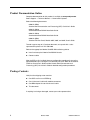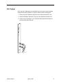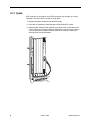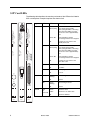
1
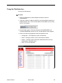
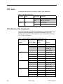
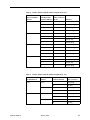
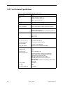
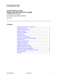
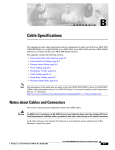
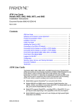
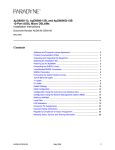
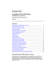
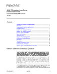
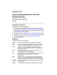
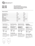
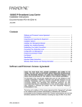
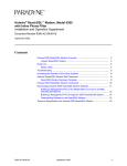
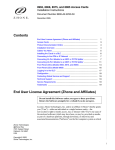
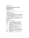
Hotwire® Shelf Concentration and Processing (SCP) Card Installation Instructions Document Number 8400-A2-GZ40-10 October 2003 Hotwire Shelf Concentration and Processing Card A Hotwire® Shelf Concentration and Processing (SCP) card is a circuit card assembly that comprises a parent card with an ATM switch, a backplane interface, a processor, a cell multiplexer/demultiplexer, and an uplink childcard. The childcard determines the type of ATM uplink supported by the SCP card. When the SCP card is used in a Hotwire 8620 or 8820 GranDSLAM chassis, it aggregates DSL traffic from each of the DSL port cards in the chassis on the chassis’s backplane bus and concentrates it onto an ATM interface. The following models are available: SCP Card Model ATM Uplink Childcard 8411-A1-000 DS3 8412-A1-000 OC3/STM1 Multimode Fiber 8413-A1-000 OC3/STM1 Single Mode Fiber Intermediate Reach (15 km) 8414-A1-000 OC3/STM1 Single Mode Fiber Long Reach (40 km) 8416-A1-000 8-Port DS1 IMA (Inverse Multiplexing over ATM) 8417-A1-000 8-Port E1 IMA The SCP card supports the following line cards: 8955 ReachDSL ATM Card 8965 ADSL ATM Card 8985 SHDSL ATM Card With a Management Communications Controller (MCC) card installed in the same chassis, the SCP card also supports Hotwire Time Division Multiplexer (TDM) SDSL and SHDSL cards, Models 8775, 8777, 8779, and 8799. 8400-A2-GZ40-10 October 2003 1 Product Documentation Online Complete documentation for this product is available at www.paradyne.com. Select Support → Technical Manuals → Hotwire DSL Systems. Select the following documents: 8400-A2-GB20 Hotwire Shelf Concentration and Processing (SCP) Card User’s Guide 8620-A2-GN20 Hotwire 8620 GranDSLAM Installation Guide 8820-A2-GN20 Hotwire 8820 GranDSLAM Installation Guide 8900-A2-GB20 Hotwire ATM Line Cards, Models 8955, 8965, and 8985, User’s Guide To order a paper copy of a Paradyne document, or to speak with a sales representative, please call 727-530-2000. Refer to the appropriate Hotwire GranDSLAM installation guide to: Install and set up the Hotwire GranDSLAM chassis Connect cables After the SCP card is installed, there are configuration procedures that must be performed before you can begin to use the DSL port cards. Refer to the Hotwire ATM Line Cards User’s Guide and the Hotwire Shelf Concentration and Processing (SCP) Card User’s Guide for detailed configuration procedures. Package Contents Verify that the shipping carton contains: One SCP card in an anti-ESD bag One 14-foot serial cable with modular connectors One DB9 adapter for use with the serial cable This document If anything is missing or damaged, contact your sales representative. 2 October 2003 8400-A2-GZ40-10 Installing the SCP Card SCP cards can be installed in: Slot A, Slot B, or both, of the 8820 GranDSLAM Slot A of the 8620 GranDSLAM Procedure To install the Hotwire SCP Card in a GranDSLAM chassis: 1. If there is a filler plate covering the slot, remove it. 2. Remove the yellow screw covers. 3. Insert the card into the card guides of the slot on the chassis. Slot A POWER A ALARMS B Fan Major Minor SYS TEM SYST EM OK Alm OK Test Alm Test ETHE RNET ETHER NET TX RX Coll TX SYST EM RX Coll OK DSL PORT Alm Test 1 2 ETHE RNET 3 4 TX RX Coll DSL MCP POWER ENTRY MODULE LEFT UNIT: LINE A RIGHT UNIT: LINE B 48V NEG 48V NEG POWER ENTRY MODULE LEFT UNIT: LINE A RIGHT UNIT: LINE B 48V RTN 48V RTN SCM CLOCK SERIAL AC A MCC ALARM 2 4 6 8 B SERIAL ALARM CLOCK SMCM 1 3 5 7 LAN/WAN SLOT A 10 12 14 16 18 11 13 15 17 WARNING! POWER MUST BE DISCONNECTED AT THE SOURCE BEFORE REMOVING OR INSTALLING THIS PWR ENTRY MODULE WARNING! POWER MUST BE DISCONNECTED AT THE SOURCE BEFORE REMOVING OR INSTALLING THIS PWR ENTRY MODULE 9 B 03-17423 4. Carefully slide the card into the slot until the card meets the connectors on the backplane. Then press in on the insertion/ejection levers until the card is fully seated. 5. Verify that the SYSTEM Active or Standby indicator on the card’s faceplate is cycling off and on. See SCP Card LEDs on page 8. 6. Secure the card by fastening the screws on each end of the faceplate. This is required to maintain proper gasket pressure on the faceplate as well as proper air flow. 7. Attach appropriate connections to the uplink. These are described in the following sections: — DS3 Uplink on page 5 — OC3 Uplink on page 6 — IMA Uplink on page 7 8400-A2-GZ40-10 October 2003 3 Installing Two SCP Cards in the Same DSLAM Two SCP cards may be installed in one DSLAM to provide redundancy or load sharing. There are three basic configurations for paired SCP cards: Y-Cable – The OC3 ports of the two SCP cards are connected to the same uplink device. If the active SCP card fails, the backup SCP card automatically becomes the uplink. See Equipment List on page 15 for available Y-cables. Dual Link – Automatic switching occurs in the event of failure, but the SCP cards are connected to different uplink devices. Load Sharing – Both SCP cards are active, and connected to different uplink devices. In the event of the failure of one of the cards, Dual Link redundancy must be manually enabled. If you use two SCP cards configured for redundancy, and intend to manage the chassis through the active card’s Ethernet port, each card must have its own connection to your hub (through the connector marked LAN Slot A or B). The cable cannot be switched after the backup SCP card becomes the active card. Also, since the two SCP cards share the same MAC address, they cannot both be connected to switch ports on your Ethernet switch. 4 October 2003 8400-A2-GZ40-10 DS3 Uplink SCP cards with a DS3 uplink have two BNC jacks: one for the transmit direction and one for the receive direction. To cable an SCP card with an DS3 uplink: 1. Connect the input cable to the RX jack on the faceplate of the SCP card. 2. Connect the output cable to the TX jack on the faceplate of the SCP card. 3. If the chassis is mounted in a rack, direct the cables toward the nearest rail and fasten them with cable ties. SYS TEM Acti ve Stan dby Alarm Test ETH ERN ET TX RX UPL INK LK 1 TX RX S3 P-D SC 11 84 03-17463 8400-A2-GZ40-10 October 2003 5 OC3 Uplink SCP cards with an OC3 uplink use an SFP transceiver that accepts an LC-type connector. To cable an SCP card with an OC3 uplink: 1. Remove the plastic dustcover from the SFP socket. 2. Insert the LC connector of your fiber optic cable into the SFP socket. 3. Observing the minimum bend radius for your cable, fasten it with cable ties in such a way that it will not be kinked or snagged in the course of other cabling. If you do not know the specifications for your cable, maintain a radius of at least ten times the cable diameter. SY ET ST EM Ac tiv e Sta nd Ala by rm Te st HE RN TX ET RX UP LIN K LK 1 SCP-OC3 8412 03-17419 6 October 2003 8400-A2-GZ40-10 IMA Uplink SCP cards with an IMA uplink have an RJ45M-type 50-position connector with eight Tip/Ring and eight Tip1/Ring1 connections that conforms to ANSI T1.403-1999. The following splitter cables are available: Feature Number 8026-F1-001 for the Model 8416 SCP card terminates in eight 8-pin modular jacks. See Table 2, Feature Number 8026-F1-001 Pin Assignments, on page 12. To connect the SCP card to a switch, attach the modular jacks of the 8026-F1-001 cable to T1/E1 crossover cables, and attach the crossover cables to the switch. Feature Number 8027-F1-001 for the Model 8417 SCP card terminates in 16 BNC jacks. See Table 3, Feature Number 8027-F1-001 Pin Assignments, on page 13. To cable an SCP card with an IMA uplink: 1. Feed the supplied cable tie through the openings in the base of the 50-position connector. SY ST EM 2. Fasten the splitter cable to the connector with the captive panhead screw. ET HE RN TX ET RX UP 3. Wrap the cable tie around the cable and fasten it. If any ferrite chokes are supplied with the SCP card, they must be installed to meet EMI requirements. Install the choke or chokes as close as possible to the 50-position connector. Hold them in place with an adjacent cable tie. Ac tiv e St an d Ala by rm Te st LI NK LK 1 LK 2 LK 3 LK 4 LK 5 LK 6 LK 7 LK 8 Panhead Screw Supplied Cable Tie Mount Cable Tie SCP-IMA 8417 03-17422 8400-A2-GZ40-10 October 2003 7 SCP Card LEDs The following table describes the meaning and states of the LEDs on the Hotwire SCP card faceplate. Example faceplates are shown at left. LED LED is . . . SYSTEM Active Green, This SCP card is the active card Slow-cycling and is functioning normally. Slow-cycling describes a recurring pulse when the LED is on longer than off at a ratio of approximately 10:1. SY Type EM ST y e db tiv an arm st Ac St Al Te SCP card failure. System processing functions have stopped. Off No power to card, or this is the standby SCP card. H ER N ET TX TX TX ET ET N N ER ER H H ET ET Green, On ET y e db tiv tan larm est S A T y e db tiv tan larm est S A T EM Ac EM Ac ST ST SY SY R X X X R R Standby U PL IN K K K IN IN PL PL U U 5 LK 1 LK LK LK 6 LK 2 LK 1 1 This SCP card is the standby card Green, Slow-cycling and is functioning normally. Slow-cycling describes a recurring pulse when the LED is on longer than off at a ratio of approximately 10:1. Green, On SCP card failure. System processing functions have stopped. Off No power to card, or this is the active SCP card. Yellow Alarm is present on the SCP card. Off No alarms. Yellow Test in progress. Off No tests. Green, Blinking Data is being transmitted. Off Inactive. Green, Blinking Data is being received. Off Inactive. Green The link is active. Yellow The link is in an alarm state. Off The link is disabled. 7 LK 3 LK 8 LK 4 LK Alarm Test TX ETHERNET TX RX RX UPLINK SCP-DS3 SCP-OC3 SCP-IMA 8411 8412 8417 03-17464 8 Indicating . . . 03-17420 LK1 or LK1–LK8 03-17421 October 2003 8400-A2-GZ40-10 Using the Default Management Address The SCP card uses Transaction Language 1 (TL1) language for Command Line Interface (CLI) commands and messages. The CLI can be used to configure and maintain the system, but the web interface is recommended. You can access the web interface using the default management address or a network address you specify using the CLI (see Setting the Management Address Using the CLI). Procedure To use the default management address: 1. Connect a PC to the Ethernet port of the SCP card using a crossover cable. 2. Access the web interface by typing the default address 10.10.10.10 into the Location field of your web browser. See Using the Web Interface on page 11. 8400-A2-GZ40-10 October 2003 9 Setting the Management Address Using the CLI The management address can be set using the CLI. Procedure To set the management address of the SCP card using the CLI: 1. Using the supplied cable and DB9 adapter, connect a PC with a terminal emulation program to the SERIAL SCM jack of your GranDSLAM. This gives you access to the CLI. 2. Log in to the SCP card using the ACT-USER command: ACT-USER::SUPERUSER:::ASN#1500 The default password, ASN#1500, will appear as asterisks on your screen. 3. Assign an IP address, netmask, and next-hop router using the ED-IPPORT command. For example: ED-IPPORT::ETH-1:100:MANUAL:IPADDR=135.26.10.37, NETMASK=255.255.255.0,GATEWAY=135.26.10.30:IS The GATEWAY in the ED-IPPORT command specifies a router for the SCP card to use to create a dynamic route upon receipt of a packet from an unknown host on the Ethernet port. To specify a default gateway for the SCP card (for the routing of packets for which there is no appropriate route), use the SET-NE-ALL command. For example: SET-NE-ALL::COM:100:::DEFROUTER=135.26.10.20; 4. Attach the SCP card to your network using the appropriate LAN connection on your GranDSLAM: — On the Model 8820 GranDSLAM, connect to the LAN SLOT A or LAN SLOT B port, depending on where the SCP card is installed. — On the Model 8620 GranDSLAM, connect to the LAN SCM port. You can now access the web interface by typing into the Location field of your web browser the IP address assigned to the Ethernet port. See Using the Web Interface on page 11. In a configuration with two SCP cards, this procedure provides access only to the active SCP card. 10 October 2003 8400-A2-GZ40-10 Using the Web Interface To access the web interface: Procedure 1. Open your web browser. (Internet Explorer Version 6 or above is recommended.) 2. Type http:// and the IP address of the SCP card into the Address field of your browser window. This is 10.10.10.10 by default, or the address you set using the CLI. For example: 3. A login window appears. Enter the default User ID (SUPERUSER) and Password (ASN#1500), and click on OK. The web interface screen appears. 4. Click on the menu tab appropriate to what you would like to do: — Configuration – To configure the system and interfaces — Status – To display statistics, status, and contents of memory — System – To display system information, download firmware, back up configurations, and modify users — Tests – To start and stop tests 8400-A2-GZ40-10 October 2003 11 BNC Jacks The following table shows the connections for BNC jacks (Model 8411). Table 1. BNC Jack Connections Connector Label Connection Description Transmit TX Pin Transmit signal Shell Transmit signal return Pin Receive signal Shell Receive signal return Receive RX IMA Interface Pin Assignments Table 2 lists connector pin assignments for Model 8416, and the Model 8417 when used with modular connectors for a 120-ohm E1 connection. Table 3 lists connector pin assignments for the Model 8417 when used with BNC connectors for a 75-ohm E1 connection. Table 2. Feature Number 8026-F1-001 Pin Assignments (1 of 2) DS1 or 120 Ohm E1 Port 8026-F1-001 50-Position Telco RJ48C Connector Connector Pinouts Pinouts Function Port 1 27 5 Data Out (Tip) 2 4 Data Out (Ring) 26 2 Data In (Tip) 1 1 Data In (Ring) 30 5 Data Out (Tip) 5 4 Data Out (Ring) 29 2 Data In (Tip) 4 1 Data In (Ring) 33 5 Data Out (Tip) 8 4 Data Out (Ring) 32 2 Data In (Tip) 7 1 Data In (Ring) 36 5 Data Out (Tip) 11 4 Data Out (Ring) 35 2 Data In (Tip) 10 1 Data In (Ring) Port 2 Port 3 Port 4 12 October 2003 8400-A2-GZ40-10 Table 2. Feature Number 8026-F1-001 Pin Assignments (2 of 2) DS1 or 120 Ohm E1 Port 8026-F1-001 50-Position Telco RJ48C Connector Connector Pinouts Pinouts Function Port 5 39 5 Data Out (Tip) 14 4 Data Out (Ring) 38 2 Data In (Tip) 13 1 Data In (Ring) 42 5 Data Out (Tip) 17 4 Data Out (Ring) 41 2 Data In (Tip) 16 1 Data In (Ring) 45 5 Data Out (Tip) 20 4 Data Out (Ring) 44 2 Data In (Tip) 19 1 Data In (Ring) 48 5 Data Out (Tip) 23 4 Data Out (Ring) 47 2 Data In (Tip) 22 1 Data In (Ring) Port 6 Port 7 Port 8 Table 3. Feature Number 8027-F1-001 Pin Assignments (1 of 2) 75 Ohm E1 Port Function 50-Position Telco Connector Pinouts BNC Connector Port 1 Data In 1 Shell (Ring) 26 Pin (Tip) 2 Shell (Ring) 27 Pin (Tip) 4 Shell (Ring) 29 Pin (Tip) 5 Shell (Ring) 30 Pin (Tip) Data Out Port 2 Data In Data Out 8400-A2-GZ40-10 October 2003 13 Table 3. Feature Number 8027-F1-001 Pin Assignments (2 of 2) 75 Ohm E1 Port Function 50-Position Telco Connector Pinouts BNC Connector Port 3 Data In 7 Shell (Ring) 32 Pin (Tip) 8 Shell (Ring) 33 Pin (Tip) 10 Shell (Ring) 35 Pin (Tip) 11 Shell (Ring) 36 Pin (Tip) 13 Shell (Ring) 38 Pin (Tip) 14 Shell (Ring) 39 Pin (Tip) 16 Shell (Ring) 41 Pin (Tip) 17 Shell (Ring) 42 Pin (Tip) 19 Shell (Ring) 44 Pin (Tip) 20 Shell (Ring) 45 Pin (Tip) 22 Shell (Ring) 47 Pin (Tip) 23 Shell (Ring) 48 Pin (Tip) Data Out Port 4 Data In Data Out Port 5 Data In Data Out Port 6 Data In Data Out Port 7 Data In Data Out Port 8 Data In Data Out 14 October 2003 8400-A2-GZ40-10 Equipment List The following feature numbers may be used to order SCP cards, line cards, and related cables. Table 4. Feature Numbers Description Feature Number Cards SCP Card: DS3 8411-A1-000 SCP Card: OC3/STM1 Multimode Fiber 8412-A1-000 SCP Card: OC3/STM1 Single Mode Fiber Intermediate Reach 8413-A1-000 SCP Card: OC3/STM1 Single Mode Fiber Long Reach 8414-A1-000 SCP Card: 8-Port DS1 IMA 8416-A1-000 SCP Card: 8-Port E1 IMA 8417-A1-000 MCP GranDSLAM 3.0 8900-B1-211 ADSL2 ATM Line Card 24 ports Annex A 8965-B1-000 ReachDSL 2.2 ATM Line Card 24 ports 8955-B1-000 G.SHDSL ATM Line Card 24 ports 8985-B1-000 Cables 8400-A2-GZ40-10 LC-to-SC Conversion Cable for SCP Multi-Mode Fiber 8400-F1-001 LC-to-SC Conversion Cable for SCP Single Mode Fiber 8400-F1-002 Y-Cable for SCP Redundancy: LC Connections, Multi-Mode Fiber 8400-F1-003 Y-Cable for SCP Redundancy: LC connections, Single Mode Fiber 8400-F1-004 Y-Cable for SCP Redundancy: SC Connections, Multi-Mode Fiber 8400-F1-005 Y-Cable for SCP Redundancy: SC Connections, Single Mode Fiber 8400-F1-006 Y-Cable for SCP Redundancy: DS3 8400-F1-007 50-Position Connector to Eight 8-Pin Modular Jacks Cable 8026-F1-001 50-Position Connector to Sixteen BNC Jacks Cable 8027-F1-001 October 2003 15 SCP Card Technical Specifications Table 5. SCP Card Technical Specifications (1 of 2) Specifications Criteria Size Length: 10.4 inches (26.42 cm) Height: 11.15 inches (28.32 cm) Width: 1.0 inches (2.54 cm) Weight Approximately 1.7 lbs. (0.76 kg) Approvals Safety Certifications Refer to the equipment’s label for approvals on product. Power The SCP card contains a DC-to-DC converter that requires 48V power input. The 48V power is distributed through the Hotwire chassis backplane. Power Dissipation DS3: 32 watts OC3: 29 watts IMA: 32 watts Physical Environment Operating temperature 32° to 140° F (0° to 60° C) Storage temperature –4° F to 158° F (–20° C to 70° C) Relative humidity 5% to 85% (noncondensing) Shock and vibration Withstands normal shipping and handling. DS3 Uplink Specifications 16 Number of ports 1 DS3 Connector Type Two 75-ohm BNC jacks Standards Supported Operations, violations, alarm states, perrformance statistics: ANSI T1.107-1995, ANSI T1.646-1995 Output jitter: ITU G.709, ITU G.783 DS3 electrical specifications: ITU G.709 DS3/ATM physical layer interface: ATM Forum af-phy-0054.000 HEC generation, calculation, error detection: ANSI T1.646, ITU T1.646 Frame Formats PLCP, Direct Line Type B3ZS Data Rates Supported 44.736 Mbps October 2003 8400-A2-GZ40-10 Table 5. SCP Card Technical Specifications (2 of 2) Specifications Criteria OC3 Uplink Specifications Number of ports 1 OC3 Connector Type Duplex LC Socket Standards Supported ANSI T1.105.06-94 Jitter, ANSI T1.105.09 94 Jitter, ANSI T1.117.06-91, ITU-T G.957 7/95 Frame Formats OC3 or STM-1 Operation, Direct Mode only Line Type Non-Return to Zero Data Rates Supported 155.52 Mbps Facility Datalink Protocol ANSI T1.105 Format, ANSI T1.646 HEC, ITU-T I.432 Scrambler Cable Distance Model 8412 (MMF) Model 8413 (SMFIR) Model 8414 (SMFLR) 2 Km (6561.7 feet) 15 Km (49,212.6 feet) SMF fiber 40 Km (131,234 feet) SMF fiber IMA Uplink Specifications Number of ports 8 T1 or E1 Connector Type RJ45M-type (50-pin telco) Standards Supported RFC 495, ANSI T1.403, ITU G.703/G.704 Frame Formats T1: Superframe, extended Superframe E1: E1, E1-CRC Line Type T1: B8ZS E1: HDB3 Data Rates Supported T1: 1.544 Mbps per T1 (max. 8 T1) E1: 2.048 Mbps per E1 (max. 8 E1) Facility Datalink Protocol ANSI T1.403 Cable Distance T1/E1 (short haul): 200 meters (656 feet) (LBO=0, –7, –15, –22 dB) T1/E1 (long haul): 2000 meters (6561.7 feet) Important Safety Instructions The OC3 configuration of the SCP circuit card has provisions for the customer to install Class 1 laser transceivers to provide optical coupling to the telecommunications network. Once a Class 1 laser is installed, the equipment is considered to be a Class 1 laser product (Appareil à Laser de Classe 1). If the Class 1 laser device is not purchased from Paradyne Corp., the customer is responsible to insure that the Class 1 AEL (Allowable Emissions Limit) per EN/IEC 60825 is not exceeded after the laser transceivers have been installed. Do not install laser products whose class rating is greater than 1. Refer to the important safety instructions that accompany the transceiver prior to installation. Only laser Class 1 devices certified for use in the country of installation by the cognizant agency are to be utilized with this product. Also, laser warnings are to be provided in accordance with IEC 60825-1 and its Amendments 1 and 2, as well as 21 CFR 1010 and 1040.10(g). 8400-A2-GZ40-10 October 2003 17 Warranty, Sales, Service, and Training Information Contact your local sales representative, service representative, or distributor directly for any help needed. For additional information concerning warranty, sales, service, repair, installation, documentation, training, distributor locations, or Paradyne worldwide office locations, use one of the following methods: Internet: Visit the Paradyne World Wide Web site at www.paradyne.com. (Be sure to register your warranty at www.paradyne.com/warranty.) Telephone: Call our automated system to receive current information by fax or to speak with a company representative. — Within the U.S.A., call 1-800-870-2221 — Outside the U.S.A., call 1-727-530-2340 Document Feedback We welcome your comments and suggestions about this document. Please mail them to Technical Publications, Paradyne Corporation, 8545 126th Ave. N., Largo, FL 33773, or send e-mail to [email protected]. Include the number and title of this document in your correspondence. Please include your name and phone number if you are willing to provide additional clarification. Trademarks Hotwire and MVL are registered trademarks of Paradyne Corporation. All other products and services mentioned herein are the trademarks, service marks, registered trademarks, or registered service marks of their respective owners. . *8400-A2-GZ40-10* Copyright © 2003 Paradyne Corporation. Printed in U.S.A. 18 October 2003 8400-A2-GZ40-10