1
TABLE
OF CONTENTS
Table of Contents
31
Safety Instructions ...............................................
2 Installation ...........................................................
Set-Top
Box
Connection
to
Panasonic
D-VHS
VCR
..................
31
Information on Digital Television ........................ 4
Digital Television ...........................................................................
Digital Broadcasting and Cable TV ...............................................
Receiving Digital Broadcasts .........................................................
Digital Picture Formats ..................................................................
Digital Audio ..................................................................................
Information
4
4
4
5
5
on the Set-Top Box .......................... 6
Panasonic Digital STB model TU-DST51 ..................................... 6
DTV-Compatible Monitor/Receiver Compatibility .......................... 6
Congratulations
....................................................
7
Customer Record ..................................... ;.................................... 7
Care and Cleaning ........................................................................ 7
Specifications ................................................................................
7
Important
Notes ....................................................
Front and Rear View of the Set-Top Box .......... 10
Features of the Set-Top Box ..............................
Channel and Program Tuning .....................................................
Channel Tuning Using Certain Panasonic Televisions ...............
Channel Banner ..........................................................................
Unavailable Channel Selection ...................................................
ATSC Display Formats................................................................
Display Format Selection ............................................................
Aspect Ratio Selection ................................................................
Digital Interface for Panasonic D-VHS VCR ................................
Dofby Digital (AC-3) Audio ..........................................................
Getting Started ....................................................
Step t. Connect AC Power Cord ................................................
Step 2. Set-Top Box Connection to DTV-Compatible TV ...........
Step 2a, Set-Top Box Connection to Conventional TV ...............
Step 3. Antenna!Cable Connection .............................................
Step 3a. Digital TV/Standard TV Reception with
DTV-Compatible TV ....................................................................
Step 3b. DigitalW/Standard TV Reception with
Conventional TV ..........................................................................
10
10
3g. NTSC Analog Cable Connection ............................
4. Turning STB On ..............................................................
5. Switching to DTV Mode ..................................................
6. Roller Guide Menu TM ......................................................
6a. ACTION/Navigation Button ...........................................
7. TV/Cab{e Mode ...............................................................
8. Programming Available Channels ..................................
Remote Control Guide ........................................
Remote Control Functional Key Chart ........................................
Battery Installation and Precautions ............................................
Special Remote Buttons ..............................................................
Programming the Remote Control ..............................................
Remote Control Component Codes ............................................
Roller Guide Menu TM ..........................................
33
34
35
37
38
41
42
46
Navigation / ACTION Button ....................................................... 44
Antenna/Cable Mode ..................................................................
49
Channel Mapping ........................................................................ 50
Programming Available Channels ............................................... 51
Clock ...........................................................................................
52
Closed Caption ....................................................................
D-VHS VCR ................................................................................
Timer 1 and 2 ..............................................................................
NTSC Tuner Operations .............................................................
11 Troubleshooting
Table .......................................
53
54
56
58
62
11
11
12
13
14
14
15
18
18
19
19
19
20
20
21
22
Step 3c, Digital TV/Cable Reception with DTV-Compatible TV .. 23
Step 3d, Digitat TV/Cable Reception with Conventional TV ........ 24
Step 3e. Digital 8VSS Cable/Analog Cable Reception with
DTV-Compatible TV .............................................................
25
Step 3f. Digital 8VSB Cable/Analog Cable Reception with
Conventional TV ...................................................................
26
Step
Step
Step
Step
Step
Step
Step
.........................................
Set-Top Box Connection to Dolby Digital AC-3 Decoder ............ 33
Roller Guide Feature Chart ................................ 47
8 Special Features ................................................. 49
STB Location ................................................................................. 8
Connecting Cables ........................................................................ 8
AC Power Supply Cord ................................................................. 8
Antenna Installation and Orientation ............................................. 8
Antenna/Cable Connection ........................................................... 9
Front Panel ..................................................................................
Rear Panel ..................................................................................
Set-Top Box Connection to VCR ................................................ 32
Optional Connections
27
28
28
28
29
29
30
Read these
operating.
instructions
completely
before
Contents are subject to change without notice or
obligation.
Copyright 1999 by Matsushita Electric Corporation of
America. All rights reserved. Unauthorized copying and
distribution is a violation of law.
Panasonic Consumer Electronics
Division Of Matsushita
Company,
EleCtric Corporation of America
One Panasonic Way
Secaucus, New Jersey 07094
[]
SAFETY
INSTRUCTIONS
SAFETY INSTRUCTIONS
WARNING
_VARNING:
To reduce
Llser-serviceable
the risk of electric
parts inside.
Refer
The lightning flash with arrow
head within a triangle is intended
to tell the user that parts inside
the product are a risk of electric
shock to persons.
Note To CATV System Installer:
shock
servicing
do not
to qualified
remove
service
cover
or back.
No
personnel.
The exclamation point within a triangle is
inter_led to tell the user that impodant
operating and servicing instructions are
in the papers with the appliance.
This reminder is provided to cali the CATV system installer's attention to article 820-40 of
the National Electric Code that provides guidelines for proper grounding and, in particular, specifies that the cable ground shall be
connected to the grounding system of the building, as close to the point of cable entry as practical
Safety Instructions
For Digital Television
Decoder
1.
2.
3.
4.
5.
6.
6a.
7.
8.
9.
t 0.
11.
12.
13.
Ii
Read and apply the operating instructions provided with your Digital Television Decoder.
Read all of the instructions given here and retain them for later use.
Unplug this Digital Television Decoder from the wall outlet before cleaning. Do not use liquid or aerosol cleaners. Use a damp
cloth for cleaning.
Do not use attachments not recommended by the Digital Television Decoder manufacturer as they may cause hazards.
Do not use this Digital Television Decoder near water. For example: Avoid placing it near a bathtub, washbowl, kitchen sink, or
laundry tub, in a wet basement, or near a swimming pool, etc.
Do not place this Digital Television Decoder on an unstable cart, stand, or table, The Digital Television Decoder may fall,
causing serious injury to a child or adult and serious damage to the appliance. Use only with a cart or stand recommended by
the manufacturer, or sold with the Digital Television Decoder,
Wall or shelf mounting should follow the manufacturer's
instructions, and should use a mounting kit approved by the manufacturer.
An appliance and cart combination should be moved with care. Quick stops, excessive force, and uneven
surfaces may cause the appliance and cart combination to overturn.
Slots and openings in the cabinet and the back or bottom are provided for ventilation, and to insure reliable
operation of the Digital Television Decoder and to protect it from overheating.
These openings must not be
blocked or covered. The openings should never be blocked by placing the Digital Television Decoder on a bed,
sofa, rug or other similar surface. This Digital Television Decoder should never be placed near or over a radiator or heat
register. This Digital Television Decoder should not be placed in a built-in installation such as a bookcase unless proper
ventilation is provided.
Operate only from the type of power source indicated on the marking label. If you are not sure of the type of power supplied to
your home consult your television dealer or local power company. For Digital Television Decoders designed to operate from
battery power, refer to the operating instructions.
This Digital Television Decoder is equipped with a polarized alternating-current line plug (a plug having one blade wider than
the other). This plug will fit into the power outlet only one way. This is a safety feature. If you are unable to insert the plug fully
into the outlet, try reversing the plug. If the plug should still fail to fit, contact your electrician to replace your obsolete outlet. Do
not defeat the safe purpose of the polarized plug,
Do not allow anything to rest on the power cord. Do not locate this Digital Television Decoder where the cord will be abused by
persons walking on it.
Follow all warnings and instructions marked on the Digital Television Decoder.
Do not overload wall outlets and extension cords as this can result in fire or electric shock.
Never push objects of any kind in to this Digital Television Decoder through cabinet slots as they may touch dangerous voltage
points or short out parts that could result in a fire or e_ectric shock. Never spill liquid of any kind on the Digital Television
Decoder.
SAFETY
EXAMPLE OF ANTENNA GROUNDING_AS
PER NATIONAL ELECTRICAL CODE (NEC_._.._
INSTRUCTIONS
ANTENNA,
LEAD-IN
_p-_-
W_RE
GROUND
DISCHARGE
[NEC
UNIT
SECTION
810-20
/
ELECTRIC
SERVICE
GROUNDING
CONDUCTORS
POWI:: R SERVICE
GROUNDING
EUECTRODE
SYSTEM
(NEC ART 250, PART H)
14.
15.
16.
17.
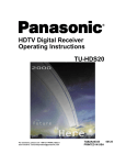
If an outside antenna is connected to the decoder equipment, be sure the antenna system is grounded so as to provide some
protection against voltage surges and built up static charges. In the U.S. Section 810 of the National Electrical Code, ANSI/
NFPA 70, and in Canada Part 1 of the Canadian Electrical Code provides information with respect to proper grounding of the
mast and supporting structure, grounding of the lead-in wire to an antenna discharge unit, size of grounding conductors,
location of antenna-discharge unit, connection to grounding electrodes, and requirements for the grounding electrode. See
Figure.
For added protection for this Digital Television Decoder during a lightning storm, or when it is left unattended and unused for
long periods of time, unplug it from the wall outlet and disconnect the antenna, This will prevent damage to the decoder due to
lightning and power-line surges.
An outside antenna system should not be located in the vicinity of overhead power lines or other electric light or power circuits,
or where it can fall into such power lines or circuits. When installing an outside antenna system extreme care should betaken to
keep from touching such power lines or circuits as contact with them might be fatal.
Unplug this Digita{ Television Decoder from the wall outlet, and refer servicing to qualified service personnel under the following
conditions:
a.
b.
c.
d.
18.
19.
When the power cord or plug is damaged or frayed.
If liquid has been spilled into the Digital Television Decoder.
If the Digital Television Decoder has been exposed to rain or water.
If the Digital Television Decoder does not operate normally by following the operating instructions.
Adjust only those
controls that are covered by the operating instructions as improper adjustment of other controls may result in damage
and will often require extensive work by a qualified technician to restore the Digital Television Decoder to normal
operation.
e.
If the Digital Television Decoder has been dropped or the cabinet has been damaged,
f.
When the Digital Television Decoder exhibits a distinct change in performance - this indicates a need for service.
Do not attempt to service this Digital Television Decoder yourself as opening or removing covers may expose you to dangerous
voltage or other hazards. Refer all servicing to qualified service personnel.
When replacement parts are required, be sure the service technician has used replacement parts specified by the manufacturer
that have the same characteristics as the original part. Unauthorized substitutions may result in fire, electric shock, or other
hazards.
20.
Upon completion of any service or repairs to this Digital Television Decoder, ask the service technician to perform routine safety
checks to determine that the decoder is in safe operating condition.
21.
WARNING: To prevent fire or shock hazard, do not expose this appliance to rain or moisture.
22.
CAUTION: TO PREVENT ELECTRIC SHOCK DO NOT USE THIS (POLARIZED) PLUG WITH A RECEPTACLE OR OTHER
OUTLET UNLESS THE BLADES CAN BE FULLY INSERTED TO PREVENT BLADE EXPOSURE.
NOTE: This equipment is designed to operate in the U.S.A. Canada and other countries where the broadcasting system and AC
house current is exactly the same as in the U.S.A. and Canada.
[]
INFORMATION ON DIGITAL TEL E VISION
Information
on Digital Television
Digital Television
In April 1997, the Federal Communications Commission (FCC) announced that by
2006, all television broadcasting will be digital. However, television stations are
required to continue broadcasting regular TV signals along side the digital signals until
2006. Cable and satellite TV are not affected by the FCC ruling.
According to the FCC, digital broadcasting must be available in the top 30 markets,
covering 50% of households, by the end of 1999.
The FCC has allocated to each of the broadcasters a fixed amount of transmitting
"space" for digital programming. At the highest resolution, High Definition (HDTV),
one (1) or two (2) programs can be transmitted within this "space." At lower
resolutions, Standard Definition (SDTV), several programs can be simultaneously
transmitted.
Broadcasters will choose their own broadcast formats. For example,
they may choose to broadcast day programs in SDTV and night sports and movies in
HDTV.
Digital Television (DTV) broadcasting will deliver crystal-clear pictures,
approaching the quality of 35mm movies, and compact disc (CD) sound.
HDTV (High Definition Television)
HDTV signal formats are 1080i (interlaced scan) and 720p (progressive scan). HDTV
provides the highest resolution picture and audio in either stereo or 5.1 channel
surround sound.
SDTV (Standard Definition Television)
SDTV signal formats are 480p and 460i. SDTV provides lower resolution, yet
presents a very sharp clear picture. Lower resolution allows broadcasters to transmit
multiple programs per channel.
Digital Broadcasting
and Cable TV
The FCC has not mandated any standards for cable operators or satellite
broadcasters at the time this manual is printed. Some cable companies have
announced plans to introduce digital cable boxes into their markets. They may
choose, however, to use the digital capability to increase the number of channels
available or to provide data capability, such as high speed modem rather than transmit
HDTV programming.
Contact your local cable provider to determine if digital cable is available and
whether a cable box is needed for converting the signals.
Receiving
Digital Broadcasts
Most households will be able to receive a digital broadcast by regular antenna with
VHF/UHF reception capability. However, like regular TV signals, it will depend on
location, terrain and environmental factors. Outdoor or attic antennas will generally be
more effective than a set-top antenna. For cable, check with your local cable provider
to find out if they will carry the DTV signal in your area.
[]
INFORMATION ON DIGITAL TELEVISION
Digital Picture
Formats
DTV supports eighteen (18) Advanced Television Systems Committee (ATSC)' display
formats, which are variations of the four (4) following formats: 1080i (interlaced), 720p
(progressive), 480p (progressive) and 480i (interlaced). The larger the number, the
higher the resolution of the picture.
Interlaced Scan
For interlaced pictures, the odd number lines (picture information) are scanned,
creating field 1, then the even number lines are scanned, creating field 2. The two
fields are interlaced to provide the entire image (one frame). This process takes 1/30th
of a second and is invisible to the human eye.
Progressive Scan
For progressive pictures, all lines in an entire frame are scanned sequentially in 1/60 th
of a second. With progressive scan, you will generally not see the thin black horizontal
scan lines (venetian blind effect) associated with an interlaced picture.
Digital Audio
For all HDTV formats, Dolby** Digital surround sound (also commonly referred to as
AC-3** or DD 5.1) is the audio standard. AC-3 will provide CD-quality sound. The
system provides 3 separate audio channels for the front speakers (left, center, right), 2
channels for the rear surround sound speakers, plus one channel for subwoofer
sound.
You will need an external audio system capable of decoding the AC-3
encoded sound to get the full surround sound effect. Otherwise, it can be connected
directly to your TV or audio system using only the stereo (left/right) audio outputs.
Note:
The stereo audio outputs are Dolby Surround compatible. You can connect a Dolby
Surround Pro Logic** decoder (not included) to the stereo audio outputs and receive
surround sound.
*The ATSC is responsible for digital television development and standards.
*'Manufactured
under license from Dolby Laboratories.
"Dolby", "AC-3", "Pro Logic" and the double-D
symbol are trademarks of Dolby Laboratories.
[]
INFORMATION ON THE SET-TOP BOX
Information
Panasonic
on the Set-Top Box
Digital Set-Top Box model TU-DST51
Current Conventional Televisions
Panasonic's digital set-top box (STB) model TU-DST51 uses specially developed
chips which allow current televisions (with A/V inputs) to display digitally broadcast
programs. The STB, which receives digital signals, has the ability to convert the
digital broadcast into National Television System Committee (NTSC)* signals (480i)
that a conventional television can display. The picture and sound quality will be
similar to small dish digital satellite systems today. Most conventional televisions will
not be able to display HDTV programs in their original format.
DTV-Compatible Televisions
The STB, by using component video connections, will allow DTV-compatible
televisions to produce pictures with incredible resolution. Component video consists
of three (3) primary color signals:
red, green and blue that together convey all
necessary picture information. The three (3) component signals have been translated
into luminance (Y) and two color difference signals (PB, PR), each on a separate wire.
The STB, depending on the capabilities of the DTV-compatible television, will give you
the choice of HDTV or SDTV format.
Audio/Visual Features
The STB contains two vital links to the future of TV. The optical Dolby Digital (AC-3)
output connection provides the highest quality surround sound when attached to an
external AC-3 decoder/receiver. A digital interface connection allows the STB to be
attached to a Panasonic digital VHS (D-VHS) VCR.
DTV-Compatible
Monitor/Receiver
Capability
HDTV-Compatible (1080i/720p)
HDTV-compatible TV models process and display high definition output from the
Panasonic STB as a 1080i or 720p format. When DTV broadcasts are available in
your viewing area, your HDTV monitor/receiver will be compatible using the STB. It
will display the 16:9 wide screen aspect ratio format.
SDTV-Compatible (480p/480i)
SDTV-compatible TV models process and display standard definition output from the
Panasonic STB as a 480p or 480i format. When DTV broadcasts are available in your
viewing area, your SDTV monitor/receiver will be compatible using the STI3. It will
display the incoming SDTV format.
[]
*NTSC is the current television system used in the U.S. It uses analog (non-digital) signals.
CONGRA TULA T/ON,£
Congratulations
Your Panasonic digital set-top box (STB) features state-of-the-art technologyfor high-quality
picture and sound with complete audio/video output jacks for your home theater system.
D'TV signals are displayed in either an interlacedor progressive format, providinga clear,
crisp picture. When connected to the STB, your HDTV-compatible monitor/receiver can
display high-definition(HD'I'V) 1080i or 720p format and standard definition (SD'FV) 480p or
480i format. This STB also has a separate NTSC tuner to provideanalog signals. Your new
STB is designed to give you many years of enjoyment.
Customer
Record
The model and serial number of this product are located on the back of the STB. You
should note the model and serial number in the space provided and retain as a
permanent record of your purchase, This will aid in identification in the event of theft
or loss. Product registration is available on-line at: www.prodreg.com\panasonic.
Model
Number
Serial
Number
Care and Cleaning
Set-Top Box (Turn STB Off)
[] For STB, avoid excessive moisture and wipe dry.
[] Avoid bumping or scraping the STB.
Remote Control
[]
[]
For Remote Control, use a soft cloth dampened with water or a mild detergent
solution. Avoid excessive moisture and wipe dry.
Do not use benzene, thinner or other petroleum based products.
Specifications
Power Source
120V AC, 60Hz
Channel Capability - NTSC and DTV
VHF/UHF + 2-69"
CATV - 1-125"
Digital Interface
TO Panasonic D-VHS VCR only
rtlgltal Audio Output
AC-3 Fiber Optic
Video Output Jacks
Specifications
1 Vpop,
75 Ohm, Phono Jack Type
Audio Output Jacks
0-2.0V rms 4+7k Ohm
NTSC Video output jack
1Vp.p, 75 Ohm, Phono Jack Type
NTSC Audio output Jeoke
0-2.0V rms 4,7k Ohm
D'FV Output (Y, Pc, PR)
75 Ohm, Phono Jack Type
are subject to change without notice or obligation.
*The digital tuning system allows channel numbers up to 999 to be displayed.
however, remains as stated.
The total channel capability,
m
IMPORTANT
NOTES
Important
Notes
STB Location
This unit can be used as part of an entertainment
center.
Consult your dealer for
available options.
£3 Avoid excessive sunlight or bright lights.
O Keep away from excessive heat or moisture.
Inadequate ventilation may cause internal
component failure.
{3 Fluorescent lighting may reduce Remote Control transmitting range.
Connecting
Cables
Component
video cables (Y, PB, PR) are provided for connection to a DTV-compatible
monitor/receiver. Shielded audio and video cables (not provided) should be used for all
other connections between components. For best results:
O Use 75 Ohm coaxial shielded cables.
£3
O
AC Power Supply
Check type of output and input connectors on your components.
Determine required cable lengths.
Cord
CAUTION: TO PREVENT ELECTRIC SHOCK, MATCH WIDE BLADE
OF PLUG TO WIDE SLOT OF AC OUTLET AND FULLY INSERT. DO
NOT USE A PLUG WITH A RECEPTACLE OR OTHER OUTLET
UNLESS THE BLADE CAN BE FULLY INSERTED TO PREVENT
BLADE EXPOSURE.
Antenna
Installation
Yag_
Log Periodic
Reflector
Plug
and Orientation
In many areas, an indoorantenna can be used to received DTV signals. Certain conditions,
however, may create a situation where an outdoor antenna is required, Tall buildings, large
metal objects (e.g., a water tower) or hills may block the line-of-sight to the TV station and
interfere with DTV signal reception. Keep the following in mind when installing and orienting
your outdoor antenna. For additional information about antennas, see the Consumer
Electronics Manufacturing Association (CEMA) website at www.cemacity.org or ask your
local dealer.
{3
Choose an antenna with directional receiving characteristics such as a Yagi, log periodic, or
reflector antenna. Avoid loop, wire bowtie, rabbit-ear and omni-directional antennas.
Use good grade 75 Ohm coax (round) cable to connect the antenna to the STB. Do not use
300 Ohm flat twin-lead cable.
{3
Place the antenna away from large metal objects. If using an indoor antenna, remember
that aluminum siding and foil-covered insulation can greatly reduce the signal strength
inside your house.
Point the antenna in the direction of the TV station. Allow a 4-6 second delay in tuning.
Watch for a program to appear on the TV. If the signal indicator is "NOT FOUND" or if a
program comes and goes, try a slightly different position for the antenna. Slowly raising or
lowering the antenna by a few feet may help.
Avoid standing in front of the antenna while adjusting its position. Move a few feet to the
rear to avoid changing the signal characteristics.
If you are located in an area serviced by two (2) different DTV stations in different directions,
you may need an antenna rotator to receive signals from both stations.
£3
®°
]
Polarized
{3
IMPORTANT
Antenna/Cable
NOTE,_
Connection
For proper reception, an antenna or cable connection is required.
Antenna
Connection
For proper reception of VHF/UHF
previous page). For best reception,
Procedure
channels, a directional antenna is required (see
an outdoor antenna is recommended.
Connect the antenna cable from your antenna.
O
Select ANTENNA, in the Roller Guide Menu "ra* SET UP Menu under Input (see Getting
Started section, Step 7).
Incoming
Home
Cable from
Antenna
75 Ohm ATSC/DTV input
on back of STB
Cable
Connection
Before connecting your cable to the STB, contact your local cable provider and ask
the following questions:
Is DTV available through your cable service?
What type of cable do you have? Standard Cable TV Signals (Cable STD), Harmonic Related
Carrier (Cable HRC) or Incremental Related Carrier (Cable IRC).
Do you need a separate cable box to receive DTV signals?
Procedure
{3
Connect the cable wire provided by your local cable provider.
{3
Select one of the following in the Roller Guide Menu TM SET UP Menu under Input (see
Getting Started section, Step 7).
Cable STD - Standard Cable TV Signals
Cable HRC - Harmonic Related Carrier
Cable IRC - Incremental Related Carrier
Incoming Cable from
Cable Provider
75 Ohm ATSC/DTV input
on back of STB
Note:
The Panasonic DTV set-top box is able to receive DTV signals from your local cable
provider only if they are transmitted in the 8VSB modulation format approved by the
FCC for DTV transmission.
Also, your cable provider may elect to transmit in the
8VSB format for only a limited period of time. Please contact your cable provider to
determine ff 8VSB modulation is available.
* Roller Guide Menu is a trademark of Panasonic Consumer Electronics Company.
U.S. Patent Pending.
[]
FRONT
ANO
REAR
VIEW
OF
THE
SET-ToP
BOX
Front and Rear View of the Set-Top
Box
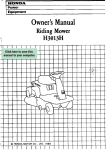
Front Panel
The following is a labeled illustration of the front panel of the STB.
Press to select Roller Guide
Menu
Remote Control Signal Sensor
Press to access and exit
Power Indicator (LED)
/
Press to select
_
NTSC channel
Panasonic
Pullto open
I
I
,I
'°w'"
{
] P_ower
I
Button
Press to navigate in menus
Set-To
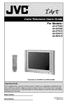
Rear Panel
The following is a labeled illustration of the rear panel of the STB.
ATSC/DTV
DTV Video and Audio
Output Jacks
NTSC Input Jack
Input Jack
AC Power Cord
/
NTSC Video and
Audio Output Jacks
Panasonic"
NTSC
iNPUT
it _'
-o©
Q
©
jT
SEPIA[ NO
_
AC t2_V _aH,
_pS
MAX
S_
-- 480 _
L
L.....____I
Dolby
Digital(Optical)
(AC-3)
Connection
Digital Interface for Panasonic
VCR
Note:
IW
D-VHS
Display F[ 'nat Selection Switch
Refer to the Table of Contents for page numbers.
FEATURES
Features
Channel
of the Set-Top
and Program
OF THE SET-ToP
BOX
Box
Tuning - DTV
Channel and program tuning in digital television is very different from current
conventional television. In DTV, up to six (6) multiple programs can exist within a
single 6 MHz channel. These programs behave as subchannels within the single
channel. When tuning to a channel, the STB will also tune to a program. Your STB
will indicate the channel and program through the on-screen Channel Banner display.
Channel and Program Tuning
The STB allows channel and program selection in the following ways:
C3 Direct Tuning (0 ~ 9 keys) - Tunes directly to a channel or program.
O Channel Up/Down Tuning (A or • buttons) - Tunes to the next or previous available
channel or program.
[3 Next Program Tuning (PROG button) - Tunes to the next program within a single 6 MHz
channel.
_1 Rapid Tuning (R-TUNE button) - Switches between the last two remembered channels or
programs.
Next Program Tuning
The PROG button on the remote control allows you to select programs within a single
6 MHz channel. Each time the PROG button is pressed, the STB will move to the next
available program within the channel.
Note:
Channel
Only programs within the current 6 MHz channel can be selected using the PROG
button. If only one (1) program appears, it indicates only one (1) program is available.
Tuning Using Certain
Panasonic
Televisions
Some Panasonic television models* will automatically switch between using the STB
or the TV to tune channels.
DTV
When the remote control is in DTV mode and either the 0 ~ 9 numeric keypad or the
Channel Up/Down (A or • buttons) is used, the television will automatically switch to
DTV input. Channel tuning will be done through the STB.
TM
When the remote control is in TV mode and either the 0 ~ 9 numeric keypad or the
Channel Up/Down (A or • buttons) is used, the television will automatically switch to
TV input. Channel tuning will be done through the TV.
*Such as CT-32XF56,
CT-36DV61,
PT-56WXF95
and other future models.
m
FEATURES
Channel
OF
THE
SET-TOP
BOX
Banner
The Channel Banner is used by all tuning methods; DTV (Native, 1080i/480p and
480p) and TV (NTSC) mode to show you which channel and program you are
currently viewing or selecting. The banner will appear in the upper right hand side of
your TV screen.
Channel Banner DTV mode
Logo indicates
Digital TV
The bar indicates 5 possible
programs to choose from, with
the 3rd program selected.
Channel
box displays
the Channel name*
Program box displays the
number followed
by the program number.
Im_
Format Info Ban_a
Aspect Ratio
DTV format and the aspect ratio
of DTV output of the STB. The
Format
Info Banner
can
be
removed via the Display Menu,
Channel
Banner
TV (NTSC)
Format
Mode
Logo indicates
DigitalTV
The bar indicates 5 possible
,s to choose from, with
program selected.
Channel
box displays
the Channel name"
Program box displays the
channel number followed
by the program number.
Aspect Ratio
Format Info Banner displays the
TV format and the aspect ratio of
TV (NTSC) output of the STB, The
Format
Info Banner
can
be
removed via the Display Menu.
*Channel box with Channel name may not appear in all situations.
FEATURES
Unavailable
Channel
OF THE SET-TOP
BOX
Selection
The unavailable channel selection screen is displayed when you select an unavailable
channel.
The following is a list of some possible
situations
where an unavailable
channel selection may occur.
[3
Tuning to a channel that is not transmitting any programs.
Tuning to a channel that stopped broadcasting programs.
The signal strength of the RF signal is insufficient to obtain consistent error free data.
Found
or Not Found
Input
The unavailable
channel
found or not found.
[3
[3
Signals
selection
screen
also indicates
whether
the input signal
is
Found signal (FOUND) - The tuner has found a signal, however, insufficient and/or
erroneous data is being received.
Not Found signal (NOT FOUND) - The tuner has not found a signal, therefore, data cannot
be received.
Displays the channel number.
A channel name and program
number are not displayed.
indicates
Indicates an
unavailable
channel was
selected and
the
signal
is
found or not
found.
STB Identification Number,
service calls.
(The number
example only).
Note:
Needed for
shown is an
The screen remains displayed for 60 seconds, then is replaced by a blank screen.
[]
FEATURES OF THE SET-TOP BOX
ATSC Display Formats
The STB converts all eighteen (18) ATSC display formats available in DTV into
viewable programming. The display formats are variations on the four (4) formats,
1080i, 720p, 480p and 480i. The following table shows the four (4) formats, their
resolutions and aspect ratios.
Display Format
1080i
720p
High Definition
16:9
480p
480i
Standard Definition
16:9 or 4:3
Selection
The STB allows you to choose a display format based on the capability of your TV or
monitor. To select the appropriate display format, use the OUTPUT MODE switch on
the rear panel of the STB.
Note: This section applies toDTV-compatib/etelevisions only
All ATSC Formats
If your TV is capable of displaying all four (4) formats, 1080i, 720p, 480p and 480i,
then set the OUTPUT MODE switch to NATIVE MODE.
1080i
1080i
720p
720p
480p
480p
480i
480i
480p, 1080i
If your TV is capable of displaying 1080i and 480p formats, then set the OUTPUT
MODE switch to 480p, 1080L
[]
1080i
1080i
720p
480p
480i
480p
FEATURES OF THE SET-TOP BOX
480p
If your TV is capable of displaying 480p format only, then set the OUTPUT MODE
switch to 480p.
1080i
720p
480p
480i
480p
NTSC Mode
If your TV is capable of displaying NTSC format only, then set the OUTPUT MODE
switch to NTSC.
1080i
720p
480p
480i
Note:
480i
When the mode switch is in the NTSC position,
(component) and 480i (composite).
the output format will be 480i
Aspect Ratio Selection
The STB changes the normal aspect ratio (picture display shape) in response to the
source signal and monitor format of your TV. You can also change the aspect ratio for
your personal viewing preference. To select an aspect ratio, press the ASPECT
button on your remote control and the STB will cycle to the next available aspect ratio
choice. The following table shows the available aspect ratios.
Source Signal
16:9
Full - Zoom - Letbox (Letterbox) Shrink
4:3
Full(No Scaling)
Full Aspect
16:9 or 4:3 picture will be displayed in the center of the viewing screen at full screen
width and height.
Zoom Aspect
The picture will be expanded uniformly (width and height) to fill the viewing screen.
The picture will be cropped, either horizontally or vertically to fit the viewing screen.
The cropped portion of the original picture will be lost from view.
Note:
To properly view Closed Captioning, the STB may, in some cases, change the aspect
ratio from Zoom to Full.
Letbox (Letterbox) Aspect
Video formats with aspect ratios greater than 16:9 will be displayed at the proper
width, so no video information is lost. Bars will appear above and below the picture.
El
FEATURES OF THE SET-TOP BOX
Shrink Aspect
The source aspect ratio will be maintained and the picture will shrink into full view on
the screen.
Sidebar Aspect
4:3 pictures will be viewed on a wide aspect TV screen with vertical bars on both sides
of the picture.
Expand Aspect
4:3 pictures will be viewed on a wide aspect TV screen with the picture digitally
"stretched" to fill the screen,
Note:
[]
See following page for illustrations of the various aspect ratios.
ASPECT RATIO FORMATS
Source
Signal
FULL
ZOOM
SIDEBAR
EXPAND
ZOOM
LETTERBOX
SHRINK
4
T
The 16:9 and 4:3 pictures
represent the incoming
source signals received
by the STB.
These pictures show the different aspect ratios
available with a 16:9 monitor format.
These pictures show the different aspect ratios
available with a 4:3 monitor format.
The top picture shows the 16:9 monitor
format available when the STB receives a
16:9 source signal.
The bottom pictures show the 16:9 monitor
formats available when the STB receives a
The top pictures show the 4:3 monitor
formats available when the STB receives a
4:3 source signal.
4:3 source signal.
t6:9 source signal.
The bottom picture shows the 4:3 monitor
format available when the STB receives a
_o
rn
B
FEATURES OF THE SET*TOP BOX
Digital Interface
for Panasonic
D-VHS VCR
The digital interface on the STB allows the transfer high speed digital data between
devices. With the digital interface, there is no need to first convert digital data into
analog, eliminating the loss of data integrity. The digital interface on the STB allows
you to connect a Panasonic digital VHS (D-VHS) VCR only.
Digital VHS (D-VHS)
The D-VHS VCR records digital data directly onto tape without digital-to-analog
conversion. The recorded data from the tape then needs to be decoded for playback
through the STB. The STB provides everything necessary to use a Panasonic D-VHS
VCR. The digital interface allows the STB to control the D-VHS VCR and can even
turn it on and simultaneously start recording through the TIMER feature.
Dolby Digital (AC-3) Audio
Dolby Digital (AC-3) 5.1 channel surround sound delivers CD-quality sound. AC-3
provides five discrete full-bandwidth channels for front left, front right, center, surround
left and surround right, plus a LFE (Low Frequency Effect) subwoofer channel.
External Dolby Decoder (Optional)
For a full Home Theater sound experience, an external AC-3 decoder and
multichannel amplifier must be connected to the STB.
Stereo Output
The internal decoder converts compressed audio data, up to 5.1 channels, into two
CD-quality stereo audio outputs, delivering stereo sound.
Note:
[]
The stereo audio outputs are Dolby Surround compatible.
You can connect a Dolby
Surround Pro Logic decoder (not included) to the stereo audio outputs and receive
surround sound.
GETTING
STARTED
Getting Started
Step 1. Connect
AC Power Cord
Plug the AC power cord into a grounded outlet.
have finished making all necessary connections.
Step
2. Set-Top
Box Connection
to DTV-Compatible
Do not turn on any devices
until you
TV
Follow this diagram when connecting the STB to a DTV-compatible TV.
DTV-COMPATIBLE
TV
Incoming signal
from antenna or
cable
i
i
STB
NOTE: AUDIO CABLES
NOT INCLUDED
DTV-COMPATIBLE
TV SETUP
Procedure
Connect video cables from the Y, PB, PR digital TV video output jacks on the STB to the Y,
PB, PR digital TV video input jacks on the DTV-compatible TV.
Connect audio cables from the left and right digital TV audio output jacks on the STB to the
left and right digital TV audio input jacks on the TV.
Note:
There are three video inputs, Y, PB, PFt. Separate component video inputs provide
luminance and color difference signals.
[]
GETTING
STARTED
Step 2a. Set-Top
Box Connection
Follow this diagram
to Conventional
when connecting
TV
the STB to a conventional
TV.
NOTE: VIDEO AND AUDIO
CABLES NOT INCLUDED
TV
Incoming signal
from antenna or
Connect the
cab1i
VIDEO
_
_
k/Rvide°audioand
I
oa0,os
"_
STB
Panason
ATSC/DTV
_
c®
_
_
NTS_
.......
,NPUT
_,.ua=l_r*du,_*,i,e.,el,o=_=_,b,,,_=r,s
_:
:_//
I
R.
UDIO
IOEO
DIGITAL
fAC 3)
©,9_; ,997D_,=_L,_or,_,r,,_=n,_='r_"t,r,,,r,,_
UT
g
INTERFACE
CONVENTIONAL
N ATW5
1080 i 4B0p
NTSC
4B0p
TV SETUP
Procedure
Move the output mode switch to the NTSC position.
Connect video cable from the video output jack on the STB to the video input jack on the
TV.
Connect audio cables from the left and right audio output jacks on the STB to the left and
right audio input jacks on the TV
Step 3, Antenna/Cable
Connection
Connect the antenna or cable wire to the ATSC/DTV
the STB.
Incoming signal
from antenna or
cable
STB
Panasonio ®
t
m
J
INPUT jack on the rear panel of
GETTING
Step 3a. Digital TV/Standard
TV Reception
with DTV-Compatible
STARTED
TV
Follow this diagram if you have a DTV-compatible TV, no cable service and you want
to receive digital channels through the STB and standard channels through the TV. An
additional antenna may be required depending on which frequencies your current
antenna can receive.
NOTE: ANTENNA, SPLITTER, RF CABLES
AND AUDIO CABLES NOT INCLUDED
DTV-Compatible
TV
SPLITTER
DIGITAL TV/STANDARD
TV RECEPTION
SETUP
WITH DTV-COMPATIBLE
TV
Procedure
Connect the antenna cable to a splitter,
Connect the splitter outputs to the STB and DTV-compatible
standard RF cables with coaxial connectors.
TV ANT (antenna) jacks using
Follow directions in Getting Started section to connect the STB to a DTV-compatible
TV.
[]
GETTING
STARTED
Step 3b. Digital TV/Standard
TV Reception
with Conventional
TV
Foltow this diagram if you have a conventional TV, no cable service and you want to
receive digital channels through the STB and standard channels through the TV. An
additional antenna may be required depending on which frequencies your current
antenna can receive.
NOTE:
ANTENNA,
CABLES, VIDEO AND
NOT INCLUDED
SPLITTER,
RF
AUDIO CABLES
"IV
SPLITTER
I
INPUT
i--k
AUDI o
_
[
ANT
IN
STB
NTSCINPUT
r_
Io¢o
i-UOOL
,0,o
FITS€OUTPUT
DIGITAL TV/STANDARD
IN_
LE
i
oo,,L
(AC.3}
AUDIOOUT
TV RECEPTION
SETUP
.....
ouT.uT
N ATIVE
1080i480p,_JL,
sE
......
NTSC k
_ 480p
WITH CONVENTIONAL
TV
Procedure
Move the output mode switch to the NTSC position,
Connect the antenna cable to the splitter.
Connect the splitter outputs to the STB and TV ANT (antenna) jacks using standard RF
cables with coaxial connectors.
Follow directions in Getting Started section to connect the STB to a conventional TV.
[]
GETTING
Step 3c. Digital TV/Cable
Reception
with DTV-Compatible
STARTED
TV
Follow this diagram if you have a DTV-compatible
TV, cable service and you want to
receive digital channels through the STB and cable channels through the cable box
(or through the TV if you have no cable box),
Optional Cable Box
NOTE:
ANTENNA, CABLE BOX, RF CABLE
AND AUDIO CABLES NOTINCLUDED
DTV-Compatible
TV
DIGITALTV
INPUT
NTSC INPUT
DIGITALTV/CABLE
RECEPTION WITH DTV-COMPATIBLETV
SETUP
Procedure
Connect the antenna cable to the STB ATSC/DTV INPUT jack.
If using a cable box, connect the cable wire from the wall jack to the cable box ANT
(antenna) IN jack using a standard RF cable with a coaxial connector. Connect the cable
box ANT (antenna) OUT jack to the DTV-compatible TV ANT (antenna) IN jack using a RF
cable.
If not using a cable box, connect the cable wire from the wall jack to the DTV-compatible TV
ANT (antenna) IN jack using a RF cable (not shown).
Follow directions in Getting Started section to connect the STB to a DTV-compatible TV.
[]
GETTING
STARTED
Step 3d. Digital TV/Cable
Reception
with Conventional
TV
Follow this diagram if you have a conventional TV, cable service and you want to
receive digital channels through the STB and cable channels through the cable box
(or through the TV if you have no cable box.
Optional Cable Box
ANT
IN
ANT
OUT
NOTE:
ANTENNA,
CABLE BOX, RF
CABLE, VIDEO AND AUDIO CABLES NOT
INCLUDED
TV
DIGITAL TV/CABLE
RECEPTION
WITH CONVENTIONAL
TV SETUP
Procedure
Move the output mode switch to the NTSC position.
Connect the antenna cable to the STB ATSC/DTV input jack.
If using a cable box, connect the cable wire from the wall jack to the cable
(antenna) IN jack using a standard RF cable with coaxial connector. Connect the
ANT (antenna) OUT jack to the TV ANT (antenna) IN jack using a RF cable.
If not using a cable box, connect the cable wire from the wall jack to the TV ANT
IN jack using a RF cable (not shown).
Follow directions in Getting Started section to connect the STB to a conventional
[]
box ANT
cable box
(antenna)
TV.
GETTING
Step 3e. Digital
8VSB Cable/Analog
Cable with DTV-Compatible
STARTED
TV
Follow this diagram if you have a DTV-compatible TV, cable service providing 8VSB
digital cable and you want to receive digital cable channels through the STB and
analog cable channels through the cable box (or through the TV if you have no cable
box).
Note:
The STB is able to receive DTV signals from your local cable provider only ff they are
transmitted in the 8VSB modulation format approved by the FCC for DTV
transmission. Also, your cable provider may elect to transmit in the 8VSB format for
only a limited period of time. Please contact your cable provider to determine ff
8VSB modulation is available
Optional Cable Box
ANT
IN
ANT
11
NOTE:
ANTENNA,
SPLITTER,
CABLE
BOX, RF CABLES AND AUDIO CABLES
NOTINCLUDED
OUT
II
DTV-CompatibleTV
8VSB SLgnal
SER'*LNO
^C12DV_OHZ MAX
_PS
[ M°°lL_°
I
DIGITAL 8VSB CABLE/ANALOG
CABLE RECEPTION
DTV-COMPATIBLE TV SETUP
I
WITH
Procedure
Connect the cable from the wall jack to the splitter using a standard RF cable with coaxial
connectors.
Connect one splitter output to the STB ATSC/DTV input jack using a RF cable.
If using a cable box, connect the other splitter output to the cable box ANT (antenna) IN
jack using a RF cable. Connect the cable box ANT (antenna) OUT jack to the DTVcompatible TV ANT (antenna) IN jack using a RF cable.
If not using a cable box, connect the other splitter output to the DTV-compatible TV ANT
(antenna) IN jack using a RF cable (not shown).
Follow directions in Getting Started section to connect the STB to a DTV-compatible TV.
[]
GETTING
STARTED
Step 3f. Digital 8VSB Cable/Analog
Cable with Conventional
TV
Follow this diagram if you have a conventional TV, cable service providing 8VSB
digital cable and you want to receive digital cable channels through the STB and
analog cable channels through the cable box (or through the TV if you have no cable
box).
Note:
The STB is able to receive DTV signals from your local cable provider
transmitted in the 8VSB modulation format approved by the
transmission. Also, your cable provider may elect to transmit in the
only a limited period of time. Please contact your cable provider
8VSB modulation is available
Analog Signal
only ff they are
FCC for DTV
8VSB format for
to determine ff
Optional Cable Box
I
I
ANT
I
ANT
NOTE: ANTENNA, SPLITTER, CABLE BOX, RF
CABLES, VIDEO AND AUDIO CABLES NOT
INCLUDED
TV
SPLITTER
8VSB Signal
INPUT
A
-
///sTo
0
,...........................
,
DIGITAL 8VSB CABLE/ANALOG
CONVENTIONAL
-
CABLE RECEPTION
TV SETUP
WITH
Procedure
Connect the cable from the wall jack to the splitter using a standard RF cable with coaxial
connectors.
Connect one splitter output to the STB ATSC/DTV input jack using a RF cable.
If using a cable box, connect the other splitter output to the cable box ANT (antenna) IN
jack using a RF cable. Connect the cable box ANT (antenna) OUT jack to the TV ANT
(antenna) IN jack using a RF cable.
If not using a cable box, connect the other splitter output to the TV ANT (antenna) iN jack
using a RF cable (not shown).
Follow directions in Getting Started section to connect the STB to a conventional TV.
[]
GETTING
Step 3g. NTSC Analog
STARTED
Cable Connection
Follow this diagram
if you want to monitor
the NTSC analog signal.
NOTE: RF CABLES, VIDEO AND AUDIO CABLES
NOT INCLUDED
Analog Signal
ANALOG
CABLE
CONVENTIONAL
RECEPTION
WITH
MONITOR SETUP
Procedure
•
Connect the cable from the analog signal source to the NTSC input,
Connect the Set Top Box NTSC video and left/right audio output to the Monitor
video and left/right audio input.
Monitor the analog signal.
[]
GETTING STARTED
Step 4. Turning
STB On
Procedure
•
•
Pressthe Remote Control DTV mode button _.
Press the POWER button.
Note:
Step 5. Switching
Monitor/'l-Vshould also be turned on.
to DTV Mode (Panasonic
TV models)
Press the Remote Control TV/VIDEO button until DTV or Component Video input
appears on the MonitorFFVscreen. Select the same mode that the STB is connected
to.
Note:
Non.Panasonicbrandtelevisionsrequire switching to the componentvideoinput.
Step 6. Roller Guide Menu
TM
Press the MENU button to display the Roller Guide Menu*. Press the • or • arrow
on the ACTION button to rotate the Roller Guide. Press the • arrow on the ACTION
button to exit the Roller Guide Menu.
r"
1
ROLLER GUIDE
MENU SELECTIONS
DISPLAY
SET UP
SET UP
/
TIMER
.J
Note:
To exit the Roller Guide Menu, press the •
MENU button.
arrow on the ACTION button or press the
*Roller Guide Menu is a trademark of Panasonic Consumer Electronics Company.
Patent Pending.
D
U.S.
GETTING
Step 6a. ACTION / Navigation
Button
Press the ACTION button to select main menu items.
highlight sub menus.
Remote
Step 7. Antenna/Cable
Press the • or • arrows to
Press the • arrow to select features. Press the • or • arrows
to scroll through options within a feature.
items.
Note:
STARTED
Press the •
ACTION
arrow to return to main menu
/ Navigation
Be careful to press ACTION in the middle of the button.
middle of the button, the arrow buttons may be activated.
Button
If you do not press in the
Mode
Select either Antenna or Cable mode, depending
are using. Cable must be 8VSB format.
on the type of incoming signal
you
Procedure
[3
In SET UP Menu, select INPUT to choose either ANTENNA or Cable.
{3
Press the • arrow, then the • and • arrows to select ANTENNA, Cable STD, Cable HRC
or Cable IRC.
ANTENNA - VHF/UHF
Cable STD - StandardCable TV Signals
Cable HRC - Harmonic Related Carrier
Cable IRC - IncrementalRelatedCarrier
Note:
Contact your local cable provider ff you are not sure which setting to use.
£1 Press the ACTION button to make your selection.
{3
Press the •
Note:
arrow to exit back to Roller Guide.
Whenever the antenna or cable mode is changed, Timer 1and Timer 2 will revert back
to default settings.
SOURCE
CH MAP
ANTENNA
ON
[]
GETTING
STARTED
Step 8. Programming
Available
Channels
YOU MUST PERFORM
THE AUTOMATIC
CHANNEL
PROGRAMMING
BEFORE
MANUALLY
ADDING AND DELETING
CHANNELS
BECAUSE
OF THE DIGITAL
TUNING
SYSTEM
USED BY THE STB.
THIS METHOD
WILL ENSURE
THAT
EVERY AVAILABLE CHANNEL
IS CAPTURED
AND STORED INTO MEMORY.
Automatic Channel Programming
The STB will scan for all available channels
normally take several minutes to complete.
Procedure
C3
£3
O
O
[3
and store them in memory.
In SET UP Menu, select PROGRAM to choose AUTO to automatically scan and store all
channels with a signal.
Press the • arrow to select AUTO.
Press the ACTION button to start the auto scan.
Press the ACTION button to cancel the auto scan or exit back to SET UP Menu after the
auto scan is complete.
Press the •
Note:
arrow once to exit back to Roller Guide.
As more digital channels
become
available
in your area, the AUTO
feature must be selected to store the new digital channels into memory.
Manual Channel Programming
After programming
all available
channels,
selectively add or delete channels.
Procedure
O
In SET UP Menu, select PROGRAM
channels.
£3
O
Press the • arrow twice to select MANUAL.
Press the ACTION button to edit channels.
you
can
use
the
MANUAL
Use the 4 and •
arrowbuttons to delete or add channels.
£3
Press the ACTION button to exit back to SET UP Menu.
O
Press the •
arrow once to exit back to Roller Guide.
AUTO
._'_ J/Ff
Automatic
feature
to
to choose MANUAL to manually add or delete
Use the A, _ arrow buttons and numeric keypad to select a channel.
Channel
MANUAL
Programming
The AUTO feature must be selected first to ensure that all
available channels are captured and stored into memory.
[]
The scan will
INSTALLA
TION
Installation
Set-Top Box Connection
to Panasonic
Follow this diagram
D-VHS VCR
when connecting
Incoming signal from antenna or cable
the STB to a D-VHS
VCR.
D-VHS VCR
DTV-Compatible
PANASONIC
TV
D-VHS VCR SETUP
Procedure
•
Connect digital interface cable from the digital interface output connection on the STB t
the digital interface input connection on the D-VHS VCR.
Note:
The STB works with a Panasonic D-VHS VCR only.
•
If using a DTV-compatible TV, follow directions in Getting Started section to connect th
STB to a DTV-compatible TV.
•
If using a conventional TV, follow directions in Getting Started section to connect the STB t
a conventional TV.
la
INSTALLATION
Set-Top
Box Connection
to VCR
Follow this diagram
when connecting
the STB to a standard
VCR.
NOTE; VIDEO AND AUDIO
NOT INCLUDED
CABLES
Incoming signal
from antenna or
TV
STB
1
I
VCR SETUP
Procedure
Move the output mode switch to the NTSC position.
Connect video cable from the video output jack on the STB to the video input jack on the
VCR.
•
Q
Connect audio cables from the left and right audio output jacks on the STB to the left and
right audio input jacks on the VCR.
Connect video cable from video output jack on the VCR to video input jack on TV.
Connect audio cables from the left and right audio output jacks on the VCR to the left and
right audio input jacks on the TV.
OPTIONAL CONNECTIONS
Optional Connec_ons
Set-Top
Box Connection
to Dolby
Digital
AC-3
Decoder
Follow this diagram to connect the STB to a Dolby Digital AC-3 decoder,
Incoming signal
from antenna or
Dolby Digital
AC-3 Dedoder
cable
STB
DTV-Compatlble
NOTE: AC-3 DECODER AND DIGITAL
AUDIO CABLE NOT INCLUDED
DOLBY DIGITAL AC-3 DECODER
TV
DIG_ALTV
INPUT
SETUP
Procedure
•
•
Connect Digital Audio cable from the Digital Audio Out connection on the STB to the Digital
Audio In connection on the Dolby Digital AC-3 decoder.
If using a D'l'V-compatible "IV, follow directions in Getting Started section to connect the
STB to a DTV-compatible TV.
It using a conventional TV. follow directions in Getting Started section to connect the STB to
a conventional TV.
[]
REMOTE CONTROL
Remote Control
ASPECT (Ratio)
EUR511157
*To conserve batt_y _le, the LIGHT func_n
can be disabled/er_bled by presszngR-TUNE
and RECALL simultaneously.
[]
REMOTE CONTROL FUNCTIONAL KEY CHART
Remote Control Functional
Key Chart
Turn €ompofterlbl
On and Off
LIGHT
Illuminate bnttona
MUTE
©
Mute audio
W/VIDEO
©
ASPECT
©
Switch between €o_sent
and "W
Change picture shape to fit format:
Full -Normal
picture shape (16:9
or 4",3)
Zoom - Expand picture unltormJy
Lstbox (Lnttorbox) - Black hats
above and b_ow picture
Shrink - Picture will $hrhlk to full
view
Eidebar/4:3 - 4:3 picture
on wide
aspect screen with vertical hats
on both sides
Expand/Just - 4:3 picture dlghaliy
"stretched"
to fill wide aspect
screefl
Component mode selection for
Remote Control
Up navlgntlon
Down navigation
Left and right navl_dlon
Exit Roller Guide Idenu
Select and adjust features
O
MENU
Roller Guide Menu
Main menu selections
Menu
ENTER
Roller Guide Menu
Menu
FROG
Select program within a channel
[]
REMOTE CONTROL FUNCTIONAL KEY CHART
Remote Control Functional
VOLUME
Key Chart
TVvolumedownand
up
Cable volume downand up
Recelvervolume
down and up
CHANNEL
GUIOE
C_
EXIT
VCR REC
Record
MOVE
REW
Move PIP
Skip I Search Rewind
Searc:h Rewind
Oecmase surround
Rewind
SEARCH
STOP
PIP channeleearch
Stop
SiZE
pLAY
Change PIP size
Play
PiP
FF
FtP
Skip/Search Fast Forward
Search Fast Forward
Incmeee Sound
Fast Fonnrd
FREEZE
"WNCR
Freeze PIP
Switch between "rv and VCR
Open / Close
OPEN/CLOSE
SWAP
PAUEE
(_)
Switch Main Picture and PiP
Still I Pause
Pause
STILL
PIP CHANNEL
VCPJDBSCH
SLOW
[]
PiP channel upI down
i Channel up / down
Center channd sound up/ down (+/-)
Slow+/RupestI Rar_lom
i SldeA/B
REMOTE CONTROL FUNCTIONAL KEY CHART
Remote Control Functional
1%"CBL DeS
OTV
DVD
LD
R-TUNE
O
TV VCR DV_LD
Off screen display
Set-top box on screen display
Time format
DBS
DTV
€o (AUX)•
O
®®
®®
@®
@
Previous channel
previous channel or program
Title
AB repeat
Next disc
Deck A/B
CD (AUX)
AUX (Cassette Deck)
RECALL
O
TY DTV
VCR
c° (Au)9
CABLE
Key Chart
DB_
Selects
Selects
channel
code
Selects chapter
Selects track
Keys 1, 2, 3, and 4 selects
Inputs,
5 = CD, 6 = Tuner, 7 =
Phono, 8 = Cassette Deck, 9 = Aux
Battery Installation
Incorrect installation can cause battery leakage and corrosion that will damage the
Remote Control
Use two AA batteries:
Remove the battery cover by pushing in near the arrow and sliding the cover
back.
Install batteries matching (+) and (-) polarity signs.
Replace the battery cover.
Precautions
•
•
•
Replace batteries in pairs.
Do not mix battery types (zinc carbon with alkaline).
Do not recharge, short-circuit, heat, burn, or disassemble batteries,
[]
SPECIAL REMOTE BUTTONS
Special Remote Buttons
ASPECT
Aspect Ratio Selections
_)
The ASPECT button changes the aspect ratio (picture display shape) in response to
the source signal and monitor format. You can also change the aspect ratio for your
personal viewing preference. Each time the ASPECT button is pressed, the STB will
cycle to the next available aspect ratio choice.
Full Aspect
16:9 or 4:3 picture will be displayed in the center of the viewing screen at full screen
width and height.
Zoom Aspect
The picture will be expanded uniformly (width and height) to fill the viewing screen.
The picture will be cropped, either hodzontally or vertically to fit the viewing screen.
The cropped portion of the odginal picture will be lost from view.
Note:
To properly display Closed Captioningin some cases; the aspect ratio shouldbe
changedfromZoom to Full.
Letbox (Letterbox) Aspect (4:3 Monitor)
Video formats with aspect ratios greater than 16:9 will be displayed at the proper
width, so no video information is lost. Black or gray bars will appear above and below
the picture.
Shrink Aspect (4:3 Monitor)
The source aspect ratio will be maintained and the picture will shrink into full view on
the screen.
Sidebar Aspect (16:9 Monitor)
4:3 pictures will be viewed on a wide aspect "IV screen with vertical bars on both sides
of the picture.
Expand Aspect (16:9 Monitor)
4:3 pictures will be viewed on a wide aspect TV screen with the picture digitally
"stretched" to fill the screen.
Note:
[]
See following page for illustrations of the various aspect ratios.
ASPECT RATIO FORMATS
Source
Signal
ZOOM
SIDEBAR
EXPAND
FULL
ZOOM
LETFERBOX
SHRINK
16
4
T
T
The 16:9 and 4:3 pictures
represent the incoming
source signals received
by the STB.
B
These pictures show the different aspect ratios
available with a 16:9 monitor format.
The top picture shows the 16:g monitor
format available when the STB receives a
These pictures show the different aspect ratios
available with a 4:3 monitor format.
The top pictures show the 4:3 monitor
formats available when the STB receives a
16:9 source signal.
The bottom pictures show the 16:9 monitor
formats available when the STB receives a
16:9 source signal.
The bottom picture shows the 4:3 monitor
format available when the STB receives a
4:3 source signal.
4:3 source signal.
SPECIAL REMOTE BUTTONS
TV/VIOEO
TV/Video
C)
The W/VIDEO button allows you to select the mode of your TV. Each time the TV/
VIDEO button is pressed, the TV will cycle through Channel, Video 1, Video 2, Video 3
and D'iV modes.
Note:
Menu
Not all television models will display all the modes.
MENU
O
The MENU button allows you to access and exit the Roller Guide Menu. Each time
the MENU button is pressed, the Roller Guide will appear on and disappear from the
viewing screen.
Next Program
PROG
O
The PROG button allows you to select programs within a single 6 MHz channel. Each
time the PROG button is pressed, the STB will move to the next available program
within the channel.
Note:
Rapid Tuning
Only programs within the current 6 MHz channel can be selected using the PROG
button. If only one (1) program appears, it indicates only one (1) program is available,
R-TUNE
O
The R-TUNE button quickly switches between two channels or programs. The STB
will attempt to immediately tune to the last channel or program in its memory. If
programs are no longer transmitting on the channel, the Unavailable Channel Screen
will display and the STB will automatically select the first program available on the
channel.
Recall RECALL
The RECALL button displays the Recall Screen for 6 seconds or until you press any
button (which automatically exits the Recall mode).
[]
PROGRAMMING
Programming
THE REMOTE CONTROl
the Remote Control
The Universal Remote Control can be programmed to operate many manufacturers'
components using the component function buttons for VCR, DVD, AUX (RCVR, CD,
TAPE, CASSETTE DECK and LD), CBL, D'I-V, TV, or DBS. Follow the procedures for
programming your Remote Control with and without codes for the component.
Determine the manufacturer of the component and look in the table for the code.
Note:
Programming
Be carefulto press ACTION in the middle of the button,ff you do not press in the
middle of the button, the arrow buttonsmay be activated. This will interruptyour
programming.
With Code
•
•
Confirm that the external component is plugged in and is turned on.
Turn the component off.
•
Press the ACTION and POWER button, together, for at least 5 seconds. All
mode buttons will flash, then let go of the buttons.
•
Press appropriate component button (VCR, CBL, etc.) on the Remote
Control. The pressed button will illuminate steadily. All other buttons will go
out.
•
Enter the 3-digit component code using the Remote Control numeric keypad
(0 ~ 9 buttons). If a proper code was entered, the mode button will blink twice
and go out.
Press the Remote Control POWER button to test the component. If the
procedure was successful, the component will turn on.
•
If the component does not operate with the Remote Control,
repeat the procedure using another code. (Some brands have
multiple codes.)
If an incorrect code is entered, or ff the procedure takes longer
than 30 seconds, the programming will fail.
Programming
Without
Code
This procedure searches all codes and is called the "sequence method".
•
Confirm that the external component is plugged in and is turned on.
•
Turn the component off.
*
Press the ACTION and POWER button, together, for at least 5 seconds. All
mode buttons will flash, then let go of the button.
•
Press appropriate component button on the Remote Control. The pressed
button will illuminate. All other buttons will go out.
•
Press the D, button to move forward to the next code. Press the <1 button to
move backward.
•
Note:
Press the Remote Control POWER button to test the component. If the
procedure was successful,the component willturn on.
Repeat the preceding two steps until the component code is found. It may take many attempts
before the correct code is found.
•
After the code is found, press the ACTION button to store the code.
[]
COMPONENT CODES
Component
Codes
The Universal Remote Control is capable of operating many component brands after entering a code.
Some components may not operate because memory is limited• The Universal Remote Control does not
control all features in all models.
Codes for TV
110
Panasonic
112
Pioneer
222
Oae_o
120
Proscan
230
Emerson
141 143 144
:_uasar
1or, 103
F_adioshack
240
_entunen
Rsher
i
1100, 101,102
250.255
GE/Panasonic/
Quasar
101
H_tachi
180
Sharp
Magnavox
210, 212
Zenith/Intaq
Samsung
SeaP_"OSNI_
.
260
I
265
270
Marantz
:
290,291
:
Codes for Cable Box
Archer
531 544
Pusar
544
Citizen
005 522
Regal
130, 350, 720, 730, 731,900
Diamond
530 531 544
Rembrandt
005, 544, 702
Eastem
560
Scientific Atlanta
122, 130, 131
Gemini
522
Sprucer
OO5, 121
Teleview
001,005
,
_ent/Jerro!d
Hamlin
_
._
.
:_,_
130, 350, 720, 730, 731,900
Hitachi
810 .......
Tocom
Macom
003, 004, 005
Memorax
542
Movietime
005, 544
Oak
0_2, 702, 710
Vidaoway
OO6
Panasonic
120, 121, 132
VieWstar
541,542
Philips
006, 541,542
Zenith
000, 280
Pioneer
001,260
Zen!_rak_
Satellite
o00
K=l
004
_nika
P
700, 701
531,544
:
_
_
,
COMPONENT CODES
Codes for VCR
Admiral
Aiwa
137,160
Orion
081,136
Aka!
0!4, 015, 0J6 142
Panasonic
100, I0),125, 130
Audio Dynamic
011,240
Pentax
000, 011,300
005 013
Ph,co
081 !25_130 136 137 i50
081,136
Philips
125, 130, 150
Cenon
125, 135
Pioneer
125
Citizen
006
Proscan
000, 001,002,
Broksonic
005, 006 i41
Curtis Mathes
.....
100 i01
130, 137, 300
o0i 130,250
_
_,
.
DBX
010, 011,240
Emerson
003, 080, 081,135,
Funai
081,136,
Go Video
220, 512
i,
125,130, 150, 300, 310
!
125 1t30
!
Radio Shack
005, 009, 130, 137, 170, 210, 241
RCA
o0o,
_! o02_251_o_+_7o_ 0oi_O
Realistic
005, 009, 130, 137, 210, 241
+ *
Samsqng
Hitachi
J.C. Penney
JVC
LXI
Mamntz
Memorex
136, 243, 250
137
Multitech
san_q
005+ O_
Scott
001,002, 004, 009,081,136,
330, 340
'
05O
Signature 2000
137, 200
Sony
140,141,142
Sylvania
125, 130, 137, 150
Tashim
006
Teac
010, 01t, 137, 240
i,
I
000, 005, 010, 011,130,
010, 011,190,
240, 520
Shaintom
000, 125, 300
_',;_iL ,
!
240
............
010, 011,240
009,
230, 241,
240, 300
000, 005, 006, 007, 008, 009, 137
•
lo0:10_i25 130 :
1130
Teknika
130, 137
_! _
004,137,330
011, t90 _40
_......... _(_+
•
000, 300
_lO,
Olympic
081,136,
o0o0o5,oo_,:oo7
000
_30; 24i; 24
Minolta
Sansui
+'_ _ i__
.....
Vector Research
011
Yamah_
00510! 0,011 ;240
Zenith
290
÷
125,130
[]
:
COMPONENT CODES
Codes for CD
_erver
550
P_
500, 501,530
Denon
600
Philips
550
Fisher
405
Pioneer
430
HarmardKardon
Quasar
500, 501,530
459, 460, 462
Sansul
432
JVC
590, 591,670
Sanyo
405
Kenwood
400, 401,450, 670
Sharp
600
Magnavox
550
Sherwood
459
Marantz
550
Mclntosh
Optimus
460 ;
430, 459
sony
s4o
Technics
500, 501,530
Victor
Codes for DVD
Saba
110
150
Thomson
110
120
_'amaba
100
Ferguson
110
N_lde
11Q
Mitsubishi
Pioneer
Codes for Cassette Deck
Technics
500, 530
Codes for DBS
Pdmestar
391
GE
170
RCA
Hitachi
050
Sony
390
Panasonic
100
Toshiba
000
001,002
Uniden
001,002
Philips
[]
:
170
COMPONENT CODES
Codes for Laser Disc
Codes for Receiver/Amplifier
710
Optimus
603, 762, 770, 771
760, 761
Panasonic
700, 701, 730
800,801,802
Philips
750
Fisher
604
Pioneer
630, 632
Garrard
655
Quasar
700,701,730
Admiral
Aiwa
Denon
Harman
657,750
_CA
Jansen
764
Sansui
603, 6531920
JVC
790,791
Sharp
800,803
Sony
740
Soundesign
82O
Teac
653, 6541 655
Technics
700, 701,730
;enwood
600
Magnavox
162
MaJrahtz
751
Mclntosh
650
658
_m_h
771
Victor
_ 631
Onkyo
603,' 630,762,770,
_'amaha
651,656
601,602
Write the code numbers for your components in the space provided below. This will serve as a
reference when you need to reprogram your remote control.
CABLE
VCR
RCVR
Cable Box
Video
Receiver or Amplifier
Laser Disc Player
co
°vo
Cassette
Recorder
DBS
Direct Broadcast
Satellite
Television
Compact
Other
Other
Ot_. _
Components
Components
Disc Player
Digital Videodisc
Other Components
[]
ROLLER GUIDE MENU
TM
Roller Guide Menu
TM
Press the MENU button on the Remote Control to display the Roller Guide Menu,
Press the • or • arrow to rotate the Roller Guide. Press the • arrow to exit the
Roller Guide Menu.
ROLLER
GUIDE MENU SELECTIONS
DISPLAY
M
SET UP
SET UP
TIMER
L
Note:
ACTION
/ Navigation
To exit the Roller Guide Menu, press the •
MENU button,
arrow on the ACTION button or press the
Button
Press the ACTION button to select main menu items, Press the • or • arrows to
highlight sub menus. Press the • arrow to select features. Press the • or • arrows
to scroll through options within a feature. Press the • arrow to return to main menu
items.
Remote
Note:
[]
ACTION ! Navigation
Button
Be careful to press ACTION in the middle of the button,
middle of the button, the arrow buttons may be activated,
If you do not press in the
ROLLER
GUIDE
FEATURE
CHART
Roller Guide Feature Chart
Roller Guide Feature Chart
g
SET UP
SET UP
f3
"
I
NPUT
SOURCE - Select one of the following:
•
ANTENNA (default setting) - VHF/UHF
•
Cable STD - Standard Cable TV
Signals
•
Cable
HRC - Harmonic
Related
Carrier
Cable IRC - Incremental
Related
Carrier
Note:
O
Contact your local cable provider if you
are not sure which setting to use.
CH Map - Select one of the following.
•
On - For automatic channel mapping
function.
Off - If you experience difficulty
receiving some digital TV stations•
O
O
AUTO - Automatically program channels
having a signal into memory.
MANUAL
Manually
add or delete
channels from memory.
CLOCK - Set time for the STB system
clock. TIME will display on screen after
pressing the POWER button, RECALL
button, or when changing channels. (Clock
must be set to use the Timer feature)•
;1/_}
O
......
in
p
:
CC (If available)
NONE - no closed captioning services.
CCl-CC4
- for closed captioning
services.
T1-T4 for text services.
!_
D SPLAY
DISPLAY
17
MONITOR
TYPE
•
•
16:9 (default setting) for wide screen•
4:3 for conventional TV screen.
[]
ROLLER
GUIDE
FEATURE
CHART
Roller Guide Feature Chart (Cont.)
O
BACKDROP
BACKDROP
Black (not recommended)
Gray (default setting)
[]
INFO
INFO - Select ON or OFF for the Format
Info Banner,
D-VHS
_,ONTROLS
MINIMIZE
/
[3
CONTROLS - Select to display D-VHS
VCR Control Panel buttons and status box.
[]
MINIMIZE - Select to minimize D-VHS
VCR Control Panel buttons to a title bar.
•
i
ill
TIMER
TIMER
[]
DAY - Select the day of the week to
activate timer.
START - Select time for timer to start.
STOP - Select time for timer to stop.
[]
CHANNEL - Select the channel for STB to
tune to at appropriate time•
£3 MODE - Select one of the following:
OFF (defaultseWng)to d_ble lJmer.
VIEW to turn on STB only. (Must tom "IV
on toview the event).
RECORD to turnon STB and startD-VHS
VCR recordingmode.
Note:
[]
Whenever the antenna or cable mode
is changed, Timer I and Timer 2 wifl
revert back to default settings.
SPECIAL FEATURES
Special Features
SET UP
Antenna/Cable
Mode
Select either Antenna or Cable mode, depending on the type of incoming signal you
are using. Cable must be 8VSB format for DTV reception.
Procedure
£]
In SET UP Menu, select iNPUT.
£3
Press the Ib arrow twice, then the • and • arrows to select ANTENNA, Cable STD, Cable
HRC or Cable IRC.
ANTENNA - VHF/UHF
Cable STD - StandardCable TV Signals
Cable HRC - HarmonicRelatedCarder
Cable IRC - Incremental Related Carrier
Note:
Contact your local cable provider ff you are not sure which setting to use.
_1 Press the ACTION button to make your selection.
O
Press the 41 arrow to exit back to Roller Guide.
Note:
Whenever the antenna or cable mode is changed, Timer I and Timer 2 will revert back
to default settings.
SET UP
SOURCE
CH MAP
ANTENNA
ON
[]
SPECIAL FEATURES
Channel Mapping
Select ON for automatic channel mapping functions. The Channel Mapping feature
allows the STB to match the actual DTV broadcast channel (assigned to your local TV
station) to the channel number that the station uses to identify itself. For example,
local channel 4 may actually be broadcasting digital programming on channel 60. The
STB will automatically tune to channel 60 and the readout will display as channel 4.
The user must input channel 4 in order to receive this channel.
Select OFF if you experience difficulty in receiving some digital TV stations. In this
case, the STB will display the actual DTV broadcast channel number assigned by the
FCC (Federal Communications
Commission). Using the example above, local
channel 4 may be broadcasting digital programming on 60. The STB will tune to
channel 60 and the readout will display channel 60. The user must input channel 60
in order to receive this channel,
Note:
In order for the Channel Mapping function to work properly, Auto Programming must
be performed after selecting Channel Mapping ON or OFF.
Procedure
[]
[]
O
[]
OI
O
[]
Press
Press
Select
Press
Press
Press
Press
the MENU button on the remote control to display the Roller Guide Menu.
A•
arrows to rotate the Roller Guide.
SET UP in Roller Guide Menu.
the ACTION button to display the main menu items.
the • arrow, then press the • arrow to select CH Map.
the • arrow,
A• arrows to select ON or OFF.
[]
[]
Press the ACTION button to enter your selection,
Press MENU button to exit the Roller Guide Menu.
SET UP
SOURCE
CH MAP
[]
ANTENNA
ON
SPECIAL
FEATURES
Programming
Available Channels
You must perform the automatic channel programming before manually adding and
deleting channels because of the digital tuning system used by the STB. This method
will ensure that every available channel will be captured and stored into memory.
Automatic Channel Programming
The STB will scan for all available channels
normally take several
Procedure
£3
O
O
[3
[3
minutes
and store them in memory.
The scan wilt
to complete.
In SET UP Menu, select PROGRAM to choose AUTO to automatically scan and store all
channels with a signal.
Press the • arrow to select AUTO.
Press the ACTION button to start the auto scan.
Press the ACTION button to cancel the auto scan or exit back to SET UP Menu after the
auto scan is complete.
Press the •
Note:
arrow once to exit back to Roller Guide.
As more digital channels
become available
in your area, the AUTO
feature must be selected to store the new digital channels into memory.
Manual Channel Programming
After programming
all available
channels,
selectively add or delete channels.
you
can
use
the MANUAL
feature
to
Procedure
[3
In SET UP Menu, select PROGRAM
channels.
to choose MANUAL to manually add or delete
O
O
Press the • arrow twice to select MANUAL.
Press the ACTION button to edit channels.
Use the A, • arrowbuttonsandnumerickeypadto selecta channel.
Use the •
and • arrowbuttonsto delete or addchannels.
Press the ACTION button to exit back to SET UP Menu,
O
Press the •
arrow once to exit back to Roller Guide,
SET UP
AUTO
MANUAL
The AUTO feature must be selected first to ensure that all
available channels are captured and stored into memo_j.
[]
SPECIAL
FEATURES
Clock
Set the time for the STB system clock. TIME will display on screen after pressing the
POWER button, RECALL button, or when changing channels. (Clock must be set to
use the "Rmer feature).
o
In SET UP Menu, select CLOCK to set the STB clock.
O
Press the I_ arrow twice to move to the day field.
O
Use the • and • arrowsto selectthe day.
Press the ACTION button.
O
Press the • arrow once, then the lip arrow once to move to the time field.
O
Press the I_ arrow once to move to the minutes.
Usethe •
Use the •
and • arrowsto selectthe hour.
and • arrowsto selectthe minutes.
Note:
The time field must be completely entered before the time can be stored.
O Press the ACTION button to store the time.
O
Press the •
arrow twice to return to Roller Guide.
DAY
TIME
[]
- :__
SPECIAL FEATURES
(Closed Captioned)
The STB contains a built-in decoder that is capable of providing a visual display of the
audio portion, The program viewed must provide Closed Captioning (CC) for the
television to display it. CC is displayed in the form of text across the screen (white or
colored letters on black background). It allows the viewer to read the dialogue of a
television program or other information.
[]_ Mode
£3 In SET UP Menu, selectCC (ClosedCaption) MODE
£3
Press the •
arrow to select _
£3
Press the •
arrow, then the •
MODE
or •
arrow
to select NONE,
CC1, CC2,
CC3,
CC4, Tt,
"1"2,
T3 or T4.
CAPTION NONE - Use when Closed Caption is not desired.
CAPTION CC1 - For video related information that can be displayed (up to 4 lines of script
on the screen, where ft does not obstruct relevant parts of the picture). Script can be in any
language.
CAPTION CC2 - Another mode used for video related information.
CAPTION CC3 and CC4 - Other modes used for video related information.
TEXT T1 - Blanks out a large portion of the picture on the television screen, and displays
program guide or any other information currently being transmitted.
TEXT T2, T3 & T4 - Other Modes that display information and blank out a large portion of
the picture on the television screen.
£3
Press ACTION
once, then the 4
arrow to return to Roller Guide.
SET UP
Notes:
To properly display Closed
changed from Zoom to Full
Caption,
in some cases, the aspect
ratio should be
Do not set Close Caption on STB and TV at the same time. This will prevent captioning
from superimposing.
[]
SPECIAL
FEATURES
D-VHS
D-VHS VCR Control Panel
The STB allows you to control a Panasonic D-VHS VCR through the digital interface.
The on-screen panel of D-VHS VCR control buttons in the D-VHS menu lets you
record and playback digital programs.
Note: The STB mustbe on whenD-VHS VCR is recording.
Control Panel
O In D-VHS Menu,selectControls.
[] Useq, Ib, • and • arrowbuttonsto selecta command.
_1 Pressthe ACTION buttonto executethecommand.
[] Press • arrowtwiceto exitto Roller Guide.
Note:
A status box will appear in the upper dght comer describing the command being
executed.
Minimizing Control Panel
The STB also allows you to minimize the D-VHS VCR control panel into a title bar, to
reduce the portion of the picture blocked by the control panel.
Title Bar
O
[3
In D-VHS Menu, select Minimize.
Press the ACTION button to minimize the control panel into a title bar.
[]
[]
Use • and Ib arrow buttons to select a command,
Press the ACTION button to execute the command.
E3
O
Select A, then press the ACTION button to maximize the control panel.
Press • arrow once to exit to Roller Guide.
Note:
[]
The title bar will appear at the bottom of the screen.
SPECIAL FEATURES
D-VHS VCR Status Messages
The STB will report status information about the D-VHS VCR in the status box. The
following table is a list of possible status messages.
Command or Event
Status Message
REW
ReWinding
STOP
Stop
FF
FastForwarding
pLAY
Playing
PAUSE _
_I
REC
Recording
D-vHs empty
_
Play: Fast Forward
Forward Searching
Play: Fast Rewind
Reverse Searching
_No_'_bt¢
Analog tape loaded
AnalogTape
D-VHS reported error
Error
....
m
SPECIAL
FEATURES
TIMER
Timer
I and Timer 2
The STB contains two timers that are capable of turning the STB on and off at
selected times, on selected channels and on selected days. You can also set your
STB to simultaneously turn your D-VHS VCR on to recording mode.
Timer
[3
Set up
In TIMER Menu, press the •
Note:
and •
arrows to select either TIMER 1 or TIMER 2.
TIME must be entered in CLOCK to operate TIMER features.
O
Press the • arrow twice to move to the day field.
O
Use the • and • arrowsto selectthe day.
Press the ACTION button to move to the first time field (start time).
[3
Press the •
[3
Press the ACTION button to move to the second time field (stop time).
Use the •
and•
arrowsto selectthe hour.
arrow to move to the minutes.
Use the •
and • arrowsto selectthe minutes.
Use the • and • arrowsto selectthe hour.
O
Press the • arrow to move to the minutes.
O
Usethe • and • arrows to selectthe minutes.
Press the ACTION button.
[3
Press the • arrow to move to the channel field.
[3
Usethe • and • arrowsto selectthe channel.
Press the ACTION button.
[3
[3
Press the •
Press the • and • arrows to select the mode.
OFF - Disablesthe timer.
VIEW - Turnson STB only. (MustturnTV onto viewthe event).
RECORD - Turnson STB and startsD-VHS VCR recordingmode.
Note:
[3
arrow once, then the • arrow once.
All data fields must be entered prior to selecting a mode.
Press ACTION once, then the •
arrow twice, to return to Roller Guide.
DAY
CHANNEL
MODE
Note:
[]
Times cannot overlap between the timers. The first entered timer (either Timer 1 or
Timer 2) will override the second entered timer.
SPECIAL FEATURES
The TIMER is active when the STB is OFF or ON.
The STB wilr switch to the selected channel at the
selected time set in the TIMER,
Timer Error Messages
The STB will scan the timer data fields and notify you of any problems before letting
you set the Mode. The following is a table of possible error messages.
Error Condition
Error Message
The start time was not entered
NOTICE:
Start time must be entered
The stop time conflicts with start time
NOTICE:
Stop conflicts with start time
[]
SPECIAL FEATURES
NTSC TUNER
OPERATIONS
This STB has a separate NTSC tuner. The NTSC output can be displayed on a
monitor with composite video inputs,
Main Menu
Press the NTSC button on the Remote control, Press the ACTION button on the
remote control to display the MAIN MENU. Press the • or • arrow to navigate in the
MAIN MENU. To exit the MAIN MENU, select EXIT and press the ACTION button.
"t+_
f-'tl_.l hV+l=l_LI
"...............
AUTO PROGRAM
Choose AUTO PROGRAM to automatically program all the available NTSC channels
with signals into the memory.
Procedure
{3 Press the NTSC buttonon the remotecontrol.
{3 Press the ACTION buttonto displaythe MAIN MENU.
[31 Press • or • arrowon the remotecontrolto select AUTO PROGRAM.
{3 Pressthe ACTION buttonto startAutoProgram.
Note:
When the auto programming is completed,the MAIN MENU will be displayedwith
MANUAL PROGRAM highlighted.
"LVJr±II_IIkV+l_ll"
[]
SPECIAL FEATURES
MANUAL PROGRAM
After programming all available channel, you can use the MANUAL PROGRAM
feature to selectively add or delete channels.
Procedure
O
In MAIN MENU select MANUAL PROGRAM.
O
£3
£3
Press the ACTION button on the remote control to display the menu features.
Use the • or • arrow or the numeric keypad to select a channel,
Press the • arrow to add a channel.
_3
O
Press the • arrow to delete a channel. The surrounding arrows will disappear.
Press the ACTION button twice to exit the menu.
CLOSED CAPTIONING
The NTSC tuner has a built-in decoder that is capable of providing a visual display of
the audio portion. The program viewed must provide Closed Captioning (CC) for the
monitor to display it. The closed caption is displayed in the form of text across the
screen (white or colored letters on black background). It allows the viewer to read the
dialogue of a television program or other information.
Procedure
O In MAIN MENU, select CLOSED CAPTION.
D
Press the ACTION button on the remote control to display the menu features.
_1 Press • or • arrows to select OFF, C1 or C2.
CAPTION OFF - Use when Closed Caption is not desired.
CAPTION C1 - For video related information that can be displayed (up to 4 lines
of script on the screen, where it does not obstruct relevant parts of the picture).
Script can be in any language.
CAPTION C2 - Another mode used for video related information.
C3 Press the ACTION button twice to exit.
II Jl
ill.=.
_ _u_l_.l==U
,1_.,I _ dto]i.........
[]
SPECIAL FEATURES
ANTENNA SOURCE
Select TV or CABLE depending on the incoming signal source.
Procedure
_3 In MAIN MENU, selectANTENNA SOURCE.
£3 Pressthe ACTION buttonon the remote controltodisplaythemenu features.
£3 Pressthe • or • arrowto selectTV or CABLE.
O Pressthe ACTION buttontwiceto exit.
CHANNEL CAPTION (LABEL)
Program channel captions (station labels) for 30 stations using up to four characters.
Procedure
£3
[3
£3
O
£3
£3
In MAIN MENU, select CHANNEL CAPTION.
Press the ACTION button on the remote control to display the menu features.
Use 4 or • arrows or numeric keypad on the remote control to select a channel to add a
caption (label).
Press the • arrow to enter the caption field.
Press • or • arrows to choose the desired character.
Press the • arrow to move to the next character.
£3
Repeat this process until all desired characters are entered.
Press the ACTION button twice to exit.
.........
[]
-
Ii.......
SPECIAL FEATURES
AUDIO SETUP
Select STEREO, SAP or MONO,
STEREO - For two channel audio reception.
SAP - (Second Audio Program). Tunes to the alternate audio channel, if
available (bilingual or descriptive audio).
MONO - One channel audio. Use when stereo signal is weak.
Procedure
[_
In MAIN MENU, select AUDIO SETUP.
£3 Press the ACTION button on the remote control to display the menu features.
C1 Press • or • arrow to select STEREO, SAP or MONO.
£3 Press the ACTION button twice to exit.
[]
TROUBLESHOOTING
Troubleshooting
Before requesting service for this unit, check the table below for a possible cause of the problem you are
experiencing. Some simple checks or a minor adjustment on your part may eliminate the problem and
restore proper operation.
If you are in doubt about some of the check points, or if the remedies indicated in the table do not solve the
problem, consult your dealer or call 1.888-VIEW-PTV (843-9788) for assistance.
No power
Check that the AC power plug is securely plugged into the power outlet.
•Check
•Check
•Check
i *Make
No reception
that
that
that
sure
equipment is connected properly.
antenna is properly installed and oriented.
the antenna or cable wire is connected properly.
the proper mode (antenna or cable) is selected.
•Make sure your local cable provider is transmitting
format.
No digital cable
in 8VSB modulation
•Make sure the proper cable mode is selected.
"Check that equipment is connected properly.
•Check if the channel is available.
.Rerun the Automatic Channel Programming to make sure all available
No picture
channels are captured and stored into memory.
•Rerun the Automatic Channel Programming to make sure all available
channels are captured and stored into memory.
Available channels are missing
Picture is distorted
.Make sure the proper display format is selected.
•Make sure the proper aspect ratio is selected.
Zoom aspect cannot be selected
•Make sure the Closed Caption feature is turned off.
.Make sure the remote control is in DTV mode.
No sound
Check that equipment is connected properly.
Wrong audio and Normal video
Check audio is set to stereo, mono, not SAP.(NTSC mode only)
The remote control is not responding
•Check that the batteries are installed with the correct polarities (+ and -).
•The batteries are depleted: Replace them with new ones.
•Point the remote control unit at the remote control sensor and operate.
.Operate the remote control unit at a distance of not more than 23 feet (7
meters) from the remote control sensor.
•Remove any obstacles between the remote control unit and remote
control sensor.
The remote control is operational,
the STB is not responding
but
The remote control is operational, but
other component(s) are not responding
[]
"Check that the AC power prug is securely plugged into the power outlet.
.Make sure the STB is on.
•Make sure the remote control is in DTV or NTSC mode.
•Check that the AC power plug is securely plugged into the power outlet.
•Make sure the component(s) are on.
-Reprogram the remote control to make sure it is programmed properly
to operate the component(s).
•Make sure the remote control is in the proper component mode (i.e. TV,
CBL, AUX, etc.).
TROUBLESHOOTING
The ACTION button is not responding
.Make sure to press ACTION in the middle of the button.
•Make sure the remote control is in DTV or NTSC mode.
No key operation (by the unit and/or
the remote control)is effective,
Set the POWER button to OFF and then back to ON. Alternatively, turn
off the power, disconnect the power plug and then reconnect it. (The STB
may not be operating propedy due to lightning, static electricity or some
other external factor).
D-VHS VCR is not responding
•Check that the AC power plug is securely plugged into the power outlet.
.Check that equipment is connected properly.
•Make sure it is a Panasonic D-VHS VCR.
D-VHS VCR does not record
Make sure STB is on.
VCP./S-Video VCR is not responding
•Check that the AC power plug is securely plugged into the power outlet.
,,Check that equipment is connected properly.
•Make sure remote control is in VCR mode.
AC-3 decoder is not responding
•Check that the AC power plug is seourely plugged into the power outlet.
.Check that equipment is connected properly.
•Make sure the clock is set.
"Check to see whether the timers have ovedapping times programmed.
.Check if the timer did not reset to default settings (antenna/cable mode
33mer does not work
was changed).
Product
Service
Do not attempt to remove the cover or repair
the unit yourself. Refer servicing to qualified
)ersonnel only.
Product
Information
For product service, product information or
assistance with product operation, consult your
dealer or call 1-888-VIEW-PTV (843-9788).
I Please have your Set-Top Box Identification
Number (ID#) available when you call. The
ID# is displayed on your TV screen when the
STB is tuned to any unavailable channel.
If you ship the product
Carefully
pack and
send it prepaid,
adequately insured and preferably in the
original carton.
Attach a postage-affixed
letter, detailing the complaint, to the outside of
the carton. DO NOT send the product to the
Executive or Regional Sales offices. They are
NO3 equipped to make repairs.
II
For servii
assistance, please call:
I
I1 888 VIEW PTV (843-9788). I
El
NOTES
[]