1
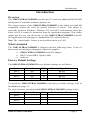
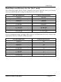
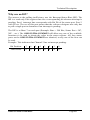
User’s Guide
Shop online at
www.omega.com
e-mail: [email protected]
OMG-ULTRACOMM422
Automatic Four Port ISA RS-422/485
Interface Board
OMEGAnet ® Online Service
www.omega.com
Internet e-mail
[email protected]
Servicing North America:
USA:
ISO 9001 Certified
Canada:
One Omega Drive, P.O. Box 4047
Stamford CT 06907-0047
TEL: (203) 359-1660
e-mail: [email protected]
976 Bergar
Laval (Quebec) H7L 5A1, Canada
TEL: (514) 856-6928
e-mail: [email protected]
FAX: (203) 359-7700
FAX: (514) 856-6886
For immediate technical or application assistance:
USA and Canada: Sales Service: 1-800-826-6342 / 1-800-TC-OMEGA®
Customer Service: 1-800-622-2378 / 1-800-622-BEST®
Engineering Service: 1-800-872-9436 / 1-800-USA-WHEN®
TELEX: 996404 EASYLINK: 62968934 CABLE: OMEGA
Mexico:
En Espan˜ol: (001) 203-359-7803
FAX: (001) 203-359-7807
e-mail: [email protected]
[email protected]
Servicing Europe:
Benelux:
Postbus 8034, 1180 LA Amstelveen, The Netherlands
TEL: +31 (0)20 3472121
FAX: +31 (0)20 6434643
Toll Free in Benelux: 0800 0993344
e-mail: [email protected]
Czech Republic:
Frystatska 184, 733 01 Karviná, Czech Republic
TEL: +420 (0)59 6311899
FAX: +420 (0)59 6311114
Toll Free: 0800-1-66342
e-mail: [email protected]
France:
11, rue Jacques Cartier, 78280 Guyancourt, France
TEL: +33 (0)1 61 37 29 00
FAX: +33 (0)1 30 57 54 27
Toll Free in France: 0800 466 342
e-mail: [email protected]
Germany/Austria: Daimlerstrasse 26, D-75392 Deckenpfronn, Germany
TEL: +49 (0)7056 9398-0
Toll Free in Germany: 0800 639 7678
e-mail: [email protected]
United Kingdom:
ISO 9002 Certified
FAX: +49 (0)7056 9398-29
One Omega Drive, River Bend Technology Centre
Northbank, Irlam, Manchester
M44 5BD United Kingdom
TEL: +44 (0)161 777 6611
FAX: +44 (0)161 777 6622
Toll Free in United Kingdom: 0800-488-488
e-mail: [email protected]
It is the policy of OMEGA to comply with all worldwide safety and EMC/EMI regulations that
apply. OMEGA is constantly pursuing certification of its products to the European New Approach
Directives. OMEGA will add the CE mark to every appropriate device upon certification.
The information contained in this document is believed to be correct, but OMEGA Engineering, Inc. accepts
no liability for any errors it contains, and reserves the right to alter specifications without notice.
WARNING: These products are not designed for use in, and should not be used for, patient-connected applications.
Contents
INTRODUCTION..........................................................................1
OVERVIEW................................................................................................ 1
W HAT ’S INCLUDED ................................................................................ 1
FACTORY DEFAULT SETTINGS ............................................................ 1
CARD SETUP ..............................................................................2
A DDRESS SELECTION............................................................................. 2
JUMPER SELECTIONS............................................................................. 4
IRQ Selection........................................................................................ 4
INTERRUPT M ODES................................................................................ 5
RS-485 ENABLE M ODES......................................................................... 6
Interface Mode Examples J1D – J4D................................................. 7
Interface Mode Examples J1D – J4D (continued)........................... 8
LINE TERMINATION ............................................................................... 9
CLOCK M ODES ...................................................................................... 10
BAUD RATES AND DIVISORS FOR THE ‘DIV1’ MODE ...................... 11
BAUD RATES AND DIVISORS FOR THE ‘DIV2’ MODE ...................... 12
INSTALLATION ........................................................................13
OPERATING SYSTEM INSTALLATION ............................................... 13
For Windows Users .......................................................................... 13
Other Operating Systems ................................................................. 13
TECHNICAL DESCRIPTION .......................................................14
FEATURES .............................................................................................. 14
INTERRUPTS .......................................................................................... 15
W HY USE AN ISP?................................................................................. 16
CONNECTOR PIN A SSIGNMENTS........................................................ 17
DB-9 Pin Assignments...................................................................... 17
DB-37 Connector Pin Assignments ................................................ 17
SPECIFICATIONS ......................................................................18
ENVIRONMENTAL SPECIFICATIONS.................................................. 18
M ANUFACTURING ................................................................................ 18
POWER CONSUMPTION........................................................................ 18
M EAN TIME BETWEEN FAILURES (MTBF) ..................................... 18
PHYSICAL DIMENSIONS........................................................................ 18
APPENDIX A - TROUBLESHOOTING .........................................19
APPENDIX B - HOW TO GET ASSISTANCEERROR! BOOKMARK NOT
DEFINED.
APPENDIX C - ELECTRICAL INTERFACE...................................22
RS-422..................................................................................................... 22
RS-485..................................................................................................... 22
APPENDIX D - ASYNCHRONOUS COMMUNICATIONS ...............23
APPENDIX E - SILK-SCREEN ....................................................24
APPENDIX F - COMPLIANCE NOTICES .....................................25
FEDERAL COMMUNICATIONS COMMISSION STATEMENT ............ 25
EMC DIRECTIVE STATEMENT ........................................................... 25
Figures
Figure 1 - Available Address Combinations......................................................2
Figure 2 - Address Selection Table ....................................................................3
Figure 3 - Port to Connector Table.....................................................................3
Figure 4 - Header J1A, Normal IRQ Mode........................................................5
Figure 5 - Header J1A & J2A, Shared IRQ Mode ...........................................5
Figure 6- Headers J1D- J4D, RS-422................................................................7
Figure 7 - Headers J1D- J4D, RS-485 ‘Auto’ Enabled, with ‘No Echo’ .......7
Figure 8 - Headers J1D- J4D, RS-485 ‘Auto’ Enabled, with ‘Echo’ .............7
Figure 9 - Headers J1D- J4D, RS-485 ‘RTS’ Enabled, with ‘No Echo’........8
Figure 10 - Headers J1D- J4D, RS-485 ‘RTS’ Enabled, with ‘Echo’ ...........8
Figure 11 - Headers J1E - J4E, Line Termination...........................................9
Figure 12 - Clocking Mode 'Divide By 4’........................................................10
Figure 13 - Clocking Mode 'Divide By 2’........................................................10
Figure 14 - Clocking Mode 'Divide By 1’........................................................10
Figure 15 - Asynchronous Communications Bit Diagram ..........................23
Introduction
Introduction
Overview
The OMG-ULTRA-COMM422 provides the PC with four additional RS-422/485
serial ports for terminals, modems, printers, etc.
The unique feature of the OMG-ULTRA-COMM422 is the ability to be RS-485
compatible without the need for special software or drivers. This ability is
especially useful in Windows, Windows NT, and OS/2 environments where the
lower level I/O control is abstracted from the application program. This ability
means that the user can effectively use the OMG-ULTRA-COMM422 in an RS485 application with existing (i.e. standard RS-232) software drivers.
Note: The ‘Auto Enable’ feature is not available on the p/n 3441.
What’s Included
The OMG-ULTRA-COMM422 is shipped with the following items. If any of
these items are missing or damaged, contact the supplier.
•
•
•
OMG-ULTRA-COMM422 Serial I/O Adapter
DB-37 to four DB-9 ‘Spider Cable’
Software
Factory Default Settings
The OMG-ULTRA-COMM422 factory default settings are as follows:
Port #
Port 1
Port 2
Port 3
Port 4
Base Address
280
288
290
298
IRQ
10
5
10
5
Electrical Specification
RS-422
RS-422
RS-422
RS-422
To install the OMG-ULTRA-COMM422 using factory default settings, refer to
Installation on page 13.
For your reference, record installed OMG-ULTRA-COMM422 settings below:
Port #
Port 1
Port 2
Port 3
Port 4
Base Address
OMG-ULTRA-COMM422
IRQ
Electrical Specification
Page 1
Card Setup
Card Setup
The OMG-ULTRA-COMM422 contains several jumper straps, which must be
set for proper operation.
Address Selection
Each port on the OMG-ULTRA-COMM422 occupies eight consecutive I/O
locations. A DIP-switch is used to set the base address for these locations.
The OMG-ULTRA-COMM422 has a unique addressing scheme that allows it to
be completely compatible with older four port RS-422/485 interface adapter (p/n
3067) and provide for the ability to select address combinations more commonly
used.
The first addressing scheme allows the OMG-ULTRA-COMM422 to select the
addresses for its ports from a table of available address combinations.
The following table shows the addressing combinations available. If different
address combinations are required, please contact Technical Support about a
custom PAL option.
Switch
6
On
On
On
Off
Off
Off
Off
On
Switch
7
On
Off
Off
On
On
Off
Off
On
Switch
8
Off
On
Off
On
Off
On
Off
On
Port
Port
Port
Port
1
2
3
4
3F8
2F8
3E8
2E8
2F8
3E8
2E8
2E0
3E8
2E8
280
288
500
508
510
518
580
588
590
598
1500
1508
1510
1518
3220
3228
4220
4228
Addresses set up by switches 1-5
Figure 1 - Available Address Combinations
Note: Each COM: port in the system should have a unique address. Typically
COM1: - COM4: addresses are 3F8, 2F8, 3E8 and 2E8 Hex.
Refer to Appendix A for common address contentions.
OMG-ULTRA-COMM422
Page 2
Card Setup
The second mode of address selection provides the compatibility mode. In this
mode the DIP-switch sets the base address and the adapter occupies 32
consecutive I/O locations. The following table illustrates the location of each
port and its relationship to the other ports.
Note: For switches 1 - 5 to become active, switches 6, 7 & 8 must be set in the
‘On’ or ‘Up’ position.
Address lines à
Address Selected
280-29F
2A0-2BF
380-39F
1A0-1BF
2E0-2FF
A9
1
Off
Off
Off
On
Off
Switch Settings
A8
A7
A6
2
3
4
On
Off
On
On
Off
On
Off Off
On
Off Off
On
On
Off
Off
A5
5
On
Off
On
Off
Off
Figure 2 - Address Selection Table
The following illustration shows the correlation between the DIP-switch setting
and the address bits used to determine the base address. In the example below,
address 2E0 is selected as a base. Address 2E0 in binary is XX 10 111X XXXX
where X = a non-selectable address bit.
A9
A5
ON
OFF
Port #
1
2
3
4
1 2 3 4 5 6 7 8
Connector Location
1
2
3
4
Address
Base+0
Base+8
Base+16
Base+24
Example (Base=2E0)
2E0-2E7
2E8-2EF
2F0-2F7
2F8-2FF
Figure 3 - Port to Connector Table
OMG-ULTRA-COMM422
Page 3
Card Setup
Jumper Selections
For ease of configuration, the headers are grouped by port. Port one headers
have a ‘J1’ prefix; Port two headers have the ‘J2’ prefix, etc. For example, the
header that controls the Port one IRQ selection is J1B; the header that controls
the Port 2 IRQ selection is J2B. The silk-screen also provides information for
configuring the adapter without the use of the manual. This is particularly useful
in field re-configuration.
IRQ Selection
Headers J1B through J4B select the interrupt request for each serial port. If
COM1: is selected, the corresponding jumper must be on the IRQ4 setting. If
COM2: is selected, the corresponding jumper must be on IRQ3.
3 4 5 6 7 9 10 11 12 15
Figure 4 – Headers J1B – J4B, IRQ Selection
Note: Most communications software applications default COM3: to IRQ4 and
COM4: to IRQ3. This requires the sharing of interrupts between COM1:
and COM3:, and between COM2: and COM4:. While this is the default, it
is not always the preferred setting. Check your software configuration
instructions to determine the most appropriate IRQ selection.
Any two or more ports can share a common IRQ by placing the jumpers on the
same IRQ setting and setting the appropriate selections at J1A through J4A.
Consult your particular software for IRQ selection. If no interrupt is desired,
remove the jumper.
OMG-ULTRA-COMM422
Page 4
Card Setup
Interrupt Modes
Headers J1A through J4A select the interrupt modes for each port. Each port
must be set in the correct mode to insure proper operation.
‘N’ indicates the (N)ormal, single interrupt per port mode. ‘S’ Indicates the
(S)hared interrupt mode, which allows more than one port to access a single IRQ.
‘M’ indicates the inclusion of a 1K ohm pull-down resistor required on one port
when sharing interrupts.
J1A
N S M
Figure 4 - Header J1A, Normal IRQ Mode
Set the jumpers to ‘S’ for shared interrupt mode on all blocks sharing an IRQ
except one. Set that port block for ‘M’. This provides the pull-down resistor
circuit that makes sharing IRQs possible. If you are using more than one OMGULTRA-COMM422 or a compatible adapter in a bus you should only have one
port set to ‘M’. The following example shows two ports sharing a single IRQ.
J1A
N S M
J2A
N S M
Figure 5 - Header J1A & J2A, Shared IRQ Mode
Set the jumper to ‘S’ if you are using more than one OMG-ULTRA-COMM422 in
a bus or to completely remove the pull-down resistor for hardware compatibility.
Setting the adapter in this configuration when it is not accompanied by a pulldown resistor will prevent the ports from triggering an interrupt.
OMG-ULTRA-COMM422
Page 5
Card Setup
RS-485 Enable Modes
RS-485 is ideal for multi-drop or network environments. RS-485 requires a tri-state
driver (not dual-state) that will allow the electrical presence of the driver to be
removed from the line. The driver is in a tri-state or high impedance condition
when this occurs. Only one driver may be active at a time and the other driver(s)
must be tri-stated. The output modem control signal Request To Send (RTS) is
typically used to control the state of the driver. Some communication software
packages refer to RS-485 as RTS enable or RTS block mode transfer.
One of the unique features of the OMG-ULTRA-COMM422 is the ability to be
RS-485 compatible without the need for special software or drivers. This ability is
especially useful in Windows, Windows NT, and OS/2 environments where the
lower level I/O control is abstracted from the application program. This ability
means that the user can effectively use the OMG-ULTRA-COMM422 in an RS485 application with existing (i.e. standard RS-232) software drivers.
Headers J1D through J4D are used to control the RS-485 mode functions for the
driver circuit. The selections are ‘RTS’ enable (silk-screen ‘RT’) or ‘Auto’ enable
(silk-screen ‘AT’). The ‘Auto’ enable feature automatically enables/disables the
RS-485 interface. The ‘RTS’ mode uses the ‘RTS’ modem control signal to
enable the RS-485 interface and provides backward compatibility with existing
software products.
Position 3 (silk-screen ‘NE’) of J1D through J4D is used to control the RS-485
enable/disable functions for the receiver circuit and determine the state of the
RS-422/485 driver. The RS-485 ‘Echo’ is the result of connecting the receiver
inputs to the transmitter outputs. Every time a character is transmitted, it is also
received. This can be beneficial if the software can handle echoing (i.e. using
received characters to throttle the transmitter) or it can confuse the system if the
software does not. To select the ‘No Echo’ mode select silk-screen position ‘NE’.
For RS-422/530/449 compatibility remove the jumpers at J1D through J4D.
Examples on the following pages describe all of the valid settings for J1D - J4D.
OMG-ULTRA-COMM422
Page 6
Card Setup
AT
RT
NE
Interface Mode Examples J1D – J4D
AT
RT
NE
Figure 6- Headers J1D- J4D, RS-422
AT
RT
NE
Figure 7 - Headers J1D- J4D, RS-485 ‘Auto’ Enabled, with ‘No Echo’
Figure 8 - Headers J1D- J4D, RS-485 ‘Auto’ Enabled, with ‘Echo’
OMG-ULTRA-COMM422
Page 7
Card Setup
AT
RT
NE
Interface Mode Examples J1D – J4D (continued)
AT
RT
NE
Figure 9 - Headers J1D- J4D, RS-485 ‘RTS’ Enabled, with ‘No Echo’
Figure 10 - Headers J1D- J4D, RS-485 ‘RTS’ Enabled, with ‘Echo’
OMG-ULTRA-COMM422
Page 8
Card Setup
Line Termination
Typically, each end of the RS-485 bus must have line terminating resistors
(RS-422 terminates at the receive end only). A 120-ohm resistor is across each
RS-530/422/485 input in addition to a 1K ohm pull-up/pull-down combination that
bias the receiver inputs. Headers J1E through J4E allow the user to customize this
interface to their specific requirements. Each jumper position corresponds to a
specific portion of the interface. If multiple OMG-ULTRA-COMM422 adapters
are configured in an RS-485 network, only the boards on each end should have
jumpers T, P & P ON. Refer to the following table for each position’s operation:
Name
P
P
T
L
L
Function
Adds or removes the 1K ohm pull-down resistor in the
RS-422/RS-485 receiver circuit (Receive data only).
Adds or removes the 1K ohm pull-up resistor in the RS-422/RS485 receiver circuit (Receive data only).
Adds or removes the 120 ohm termination.
Connects the TX- to RX- for RS-485 two wire operation.
Connects the TX+ to RX+ for RS-485 two wire operation.
P
P
T
L
L
Figure 11 - Headers J1E - J4E, Line Termination
OMG-ULTRA-COMM422
Page 9
Card Setup
Clock Modes
The OMG-ULTRA-COMM422 employs a unique clocking option that allows the
end user to select from divide by 4, divide by 2 and divide by 1 clocking modes.
These modes are selected at Headers J1C through J4C.
DIV1
DIV2
DIV4
To select the Baud rates commonly associated with COM: ports (i.e. 2400, 4800,
9600, 19.2, … 115.2K Bps ) place the jumper in the divide by 4 mode (silk-screen
DIV4).
Figure 12 - Clocking Mode 'Divide By 4’
DIV1
DIV2
DIV4
To double these rates up to a maximum rate for 230.4K bps place the jumper in
the divide by 2 (silk-screen DIV2) position.
Figure 13 - Clocking Mode 'Divide By 2’
DIV1
DIV2
DIV4
To select the maximum data rate (460.8K bps) place the jumper in the divide by 1
(silk-screen DIV1) position.
Figure 14 - Clocking Mode 'Divide By 1’
OMG-ULTRA-COMM422
Page 10
Card Setup
Baud Rates and Divisors for the ‘Div1’ mode
The following table shows some common data rates and the rates you should
choose to match them if using the adapter in the ‘Div1’ mode.
For this Data Rate
1200 bps
2400 bps
4800 bps
9600 bps
19.2K bps
57.6 K bps
115.2 K bps
230.4K bps
460.8K bps
Choose this Data Rate
300 bps
600 bps
1200 bps
2400 bps
4800 bps
14.4K bps
28.8K bps
57.6 K bps
115.2 K bps
If your communications package allows the use of Baud rate divisors, choose the
appropriate divisor from the following table:
For this Data Rate
1200 bps
2400 bps
4800 bps
9600 bps
19.2K bps
38.4K bps
57.6K bps
115.2K bps
230.4K bps
460.8K bps
OMG-ULTRA-COMM422
Choose this Divisor
384
192
96
48
24
12
8
4
2
1
Page 11
Card Setup
Baud Rates and Divisors for the ‘Div2’ mode
The following table shows some common data rates and the rates you should
choose to match them if using the adapter in the ‘Div2’ mode.
For this Data Rate
1200 bps
2400 bps
4800 bps
9600 bps
19.2K bps
38.4K bps
57.6 K bps
115.2 K bps
230.4 K bps
Choose this Data Rate
600 bps
1200 bps
2400bps
4800 bps
9600 bps
19.2K bps
28.8K bps
57.6 K bps
115.2 K bps
If your communications package allows the use of Baud rate divisors, choose the
appropriate divisor from the following table:
For this Data Rate
1200 bps
2400 bps
4800 bps
9600 bps
19.2K bps
38.4K bps
57.6K bps
115.2K bps
230.4K bps
OMG-ULTRA-COMM422
Choose this Divisor
192
96
48
24
12
8
4
2
1
Page 12
Installation
Installation
The OMG-ULTRA-COMM422 can be installed in any of the PC expansion slots.
The OMG-ULTRA-COMM422 contains several jumper straps for each port that
must be set for proper operation.
1.
2.
3.
4.
5.
6.
7.
8.
Turn off PC power. Disconnect the power cord.
Remove the PC case cover.
Locate an available slot and remove the blank metal slot cover.
Gently insert the OMG-ULTRA-COMM422 into the slot. Make sure that the
adapter is seated properly.
Replace the screw.
Install the “Spider” Cable
Replace the cover.
Connect the power cord.
Installation is complete.
Operating System Installation
For Windows Users
Start by choosing Install Software at the beginning of the CD. Choose
Asynchronous COM: Port Software, SeaCOM.
Other Operating Systems
Refer to the appropriate section of the Serial Utilities Software.
OMG-ULTRA-COMM422
Page 13
Technical Description
Technical Description
The OMG-ULTRA-COMM422 utilizes the 16550 UART. This chip features
programmable baud rates, data format, interrupt control and a 16-byte input and
output FIFO. Also available as options are the Startech 16C650 and the Texas
Instruments 16C750 UARTs, that provide deeper FIFOs (32 bytes) and enhanced
clocking features.
A second version of the OMG-ULTRA-COMM422, p/n 3441 is available without
the auto enable feature for a reduced price. If point to point RS-422 or RTS
enabled RS-485 operations are desired, this option should be considered.
Features
•
•
•
•
•
•
•
•
Automatic RS-485 driver enable/disable allows card to appear to be RS-232
requiring no additional drivers
‘PAL’ option allows for unique OEM address selection
‘Shareable’ IRQs allow more than one port to share a single IRQ
IRQs 2/9-7, 10, 11, 12, 15 supported
16550 buffered UARTs standard, 16650 and 16750 UARTS available
16 Bit address decode allows for easier integration
Speeds up to 460.8 K bps available
Multiple clocking modes insuring compatibility with existing software
products
Modem Control Signal Considerations
Some software packages require the use of the modem handshake signals such
as RTS or CTS. Refer to your application software manual to determine the
requirements for modem control signals. If no requirements are mentioned, a safe
configuration is to tie RTS to CTS. This configuration will typically satisfy the
modem control signal requirements for most communications software.
OMG-ULTRA-COMM422
Page 14
Technical Description
Interrupts
A good description of an interrupt and it’s importance to the IBM PC can be
found in the book ‘Peter Norton’s Inside the PC, Premier Edition’:
“ One of the key things that makes a computer different from any other kind of
man-made machine is that computers have the capability to respond to the
unpredictable variety of work that comes to them. The key to this capability is a
feature known as interrupts. The interrupt feature enables the computer to
suspend whatever it is doing and switch to something else in response to an
interruption, such as the press of a key on the keyboard.”
A good analogy of a PC interrupt would be the phone ringing. The phone ‘bell’
is a request for us to stop what we are currently doing and take up another task
(speak to the person on the other end of the line). This is the same process the
PC uses to alert the CPU that a task must be preformed. The CPU upon receiving
an interrupt makes a record of what the processor was doing at the time and
stores this information on the ‘stack’; this allows the processor to resume its
predefined duties after the interrupt is handled, exactly where it left off. Every
main sub-system in the PC has it’s own interrupt, frequently called an IRQ (short
for Interrupt ReQuest)..
In these early days of PC’s it was decided that the ability to share IRQs was an
important feature for any add-in I/O card. Consider that in the IBM XT the
available IRQs were IRQ0 through IRQ7. Of these interrupts only IRQ2-5 and
IRQ7 were actually available for use. This made the IRQ a very valuable system
resource. To make the maximum use of these system resources an IRQ sharing
circuit was devised that allowed more than one port to use a selected IRQ. This
worked fine as a hardware solution but presented the software designer with a
challenge to identify the source of the interrupt. The software designer
frequently used a technique referred to as ‘round robin polling’. This method
required the interrupt service routine to ‘poll’ or interrogate each UART as to it’s
interrupt pending status. This method of polling was sufficient for use with
slower speed communications, but as modems increased their through put
abilities this method of servicing shared IRQs became inefficient.
OMG-ULTRA-COMM422
Page 15
Technical Description
Why use an ISP?
The answer to the polling inefficiency was the Interrupt Status Port (ISP). The
ISP is a read only 8-bit register that sets a corresponding bit when an interrupt is
pending. Port 1 interrupt line corresponds with Bit D0 of the status port, Port 2
with D1 etc. The use of this port means that the software designer now only has
to poll a single port to determine if an interrupt is pending.
The ISP is at Base+7 on each port (Example: Base = 280 Hex, Status Port = 287,
28F… etc.). The OMG-ULTRA-COMM422 will allow any one of the available
locations to be read to obtain the value in the status register. All four status
ports on the OMG-ULTRA-COMM422 are identical, so any one of the four can
be read.
Example: This indicates that Channel 2 has an interrupt pending.
Bit Position:
Value Read:
7
0
6
0
OMG-ULTRA-COMM422
5
0
4
0
3
0
2
0
1
1
0
0
Page 16
Technical Description
Connector Pin Assignments
DB-9 Pin Assignments
Signal
GND
TX +
TXRTS+
RTSRX+
RXCTS+
CTS-
Name
Ground
Transmit Data Positive
Transmit Data Negative
Request To Send Positive
Request To Send Negative
Receive Data Positive
Receive Data Negative
Clear To Send Positive
Clear To Send Negative
Pin #
5
4
3
6
7
1
2
9
8
Mode
Output
Output
Output
Output
Input
Input
Input
Input
DB-37 Connector Pin Assignments
Port #
GND
TXRTSTX+
RXCTSRTS+
RX+
CTS+
1
33
35
17
34
36
16
18
37
15
OMG-ULTRA-COMM422
2
14
12
30
13
11
31
29
10
32
3
24
26
8
25
27
7
9
28
6
4
5
3
21
4
2
22
20
1
23
Page 17
Specifications
Specifications
Environmental Specifications
Specification
Temperature Range
Humidity Range
Operating
0º to 50º C
(32º to 122º F)
10 to 90% R.H.
Non-Condensing
Storage
-20º to 70º C
(-4º to 158º F)
10 to 90% R.H.
Non-Condensing
Manufacturing
•
IPC 610-A Class-III standards are adhered to with a 0.1 visual A.Q.L. and
100% Functional Testing.
•
All Printed Circuit boards are built to U.L. 94V0 rating and are 100%
electrically tested. These printed circuit boards are solder mask over bare
copper or solder mask over tin nickel.
Power Consumption
Supply line
3440 Rating
3441 Rating
+5 VDC
600 mA
570 mA
Mean Time Between Failures (MTBF)
Greater than 150,000 hours. (Calculated)
Physical Dimensions
Board length
Board Height including Goldfingers
Board Height excluding Goldfingers
OMG-ULTRA-COMM422
8.0 inches
4.2 inches
3.9 inches
(20.32 cm)
(10.66 cm)
(9.91 cm)
Page 18
Appendix A - Troubleshooting
Appendix A - Troubleshooting
A Serial Utility Diskette is supplied with the adapter and will be used in the
troubleshooting procedures. By using this diskette and following these simple
steps, most common problems can be eliminated without the need to call
Technical Support.
1.
Identify all I/O adapters currently installed in your system. This includes
your on-board serial ports, controller cards, sound cards etc. The I/O
addresses used by these adapters, as well as the IRQ (if any) should be
identified.
2.
Configure your adapter so that there is no conflict with currently installed
adapters. No two adapters can occupy the same I/O address.
3.
Make sure the adapter is using a unique IRQ. While the adapter does allow
the sharing of IRQs, many other adapters (i.e. SCSI adapters & on-board
serial ports) do not. The IRQ is typically selected via an on-board header
block. Refer to the section on Card Setup for help in choosing an I/O
address and IRQ.
4.
Make sure the adapter is securely installed in a motherboard slot.
5.
When running DOS or Windows 3.x refer to the Serial Utilities disk 1 and
the User Manual to verify that the adapter is configured correctly. The
supplied diskette contains a diagnostic program ‘SSD’ that will verify if an
adapter is configured properly. This diagnostic program is written with the
user in mind and is easy to use. Refer to the ‘README’ file on the supplied
diskette for detailed instructions on using ‘SSD’.
6.
For Windows 95 and Windows NT, the diagnostic tool ‘WinSSD’ is
installed in the Omega Engineering folder on the Start Menu during the
setup process. First find the ports using the Device Manager, then use
‘WinSSD’ to verify that the ports are functional.
7.
Always use the diagnostic software when troubleshooting a problem. This
will eliminate any software issues from the equation.
OMG-ULTRA-COMM422
Page 19
Appendix A - Troubleshooting
8.
The following are known I/O conflicts:
•
•
•
•
•
•
9.
The 278 and 378 settings may conflict with your printer I/O adapter.
3B0 cannot be used if a Monochrome adapter is installed.
3F8-3FF is typically reserved for COM1:
2F8-2FF is typically reserved for COM2:
3E8-3EF is typically reserved for COM3:
2E8-2EF is typically reserved for COM4:
Please refer to your included diskette for any post production manual
updates and application specific information.
10. Always use the diagnostic software when Troubleshooting a problem. This
will eliminate the software issue from the equation.
OMG-ULTRA-COMM422
Page 20
Appendix B - How To Get Assistance
Please refer to Troubleshooting Guide prior to calling Technical Support.
1.
Begin by reading through the Trouble Shooting Guide in Appendix
A. If assistance is still needed please see below.
2.
When calling for technical assistance, please have your user
manual and current adapter settings. If possible, please have the
adapter installed in a computer ready to run diagnostics.
3.
Omega Engineering maintains a Home page on the Internet. Our
home page address is www.omega.com. The latest software
updates, and n ewest manuals are available via our FTP site that can
be accessed from our home page.
4.
Technical support is available Monday to Friday from 8:30 a.m. to
6:00 p.m. eastern time. Technical support can be reached at 1-800DAS-IEEE.
RETURN AUTHORIZATION MUST BE OBTAINED FROM OMEGA BEFORE
RETURNED MERCHANDISE WILL BE ACCEPTED. AUTHORIZATION CAN
BE OBTAINED BY CALLING OMEGA CUSTOMER SERVICE AND
REQUESTING AN AUTHORIZED RETURN (AR) NUMBER.
OMG-ULTRA-COMM422
Page 21
Appendix C - Electrical Interface
Appendix C - Electrical Interface
RS-422
The RS-422 specification defines the electrical characteristics of balanced voltage
digital interface circuits. RS-422 is a differential interface that defines voltage
levels and driver/receiver electrical specifications. On a differential interface,
logic levels are defined by the difference in voltage between a pair of outputs or
inputs. In contrast, a single ended interface, for example RS-232, defines the logic
levels as the difference in voltage between a single signal and a common ground
connection. Differential interfaces are typically more immune to noise or voltage
spikes that may occur on the communication lines. Differential interfaces also
have greater drive capabilities that allow for longer cable lengths. RS-422 is rated
up to 10 Megabits per second and can have cabling 4000 feet long. RS-422 also
defines driver and receiver electrical characteristics that will allow 1 driver and up
to 32 receivers on the line at once. RS-422 signal levels range from 0 to +5 volts.
RS-422 does not define a physical connector.
RS-485
RS-485 is backwardly compatible with RS-422; however, it is optimized for
partyline or multi-drop applications. The output of the RS-422/485 driver is
capable of being Active (enabled) or Tri-State (disabled). This capability allows
multiple ports to be connected in a multi-drop bus and selectively polled. RS-485
allows cable lengths up to 4000 feet and data rates up to 10 Megabits per second.
The signal levels for RS-485 are the same as those defined by RS-422. RS-485 has
electrical characteristics that allow for 32 drivers and 32 receivers to be
connected to one line. This interface is ideal for multi-drop or network
environments. RS-485 tri-state driver (not dual-state) will allow the electrical
presence of the driver to be removed from the line. Only one driver may be active
at a time and the other driver(s) must be tri-stated. RS-485 can be cabled in two
ways, two wire and four wire mode. Two wire mode does not allow for full duplex
communication, and requires that data be transferred in only one direction at a
time. For half-duplex operation, the two transmit pins should be connected to the
two receive pins (Tx+ to Rx+ and Tx- to Rx-). Four wire mode allows full duplex
data transfers. RS-485 does not define a connector pin-out or a set of modem
control signals. RS-485 does not define a physical connector.
OMG-ULTRA-COMM422
Page 22
Appendix D - Asynchronous Communications
Appendix D - Asynchronous Communications
Serial data communications implies that individual bits of a character are
transmitted consecutively to a receiver that assembles the bits back into a
character. Data rate, error checking, handshaking, and character framing
(start/stop bits) are pre-defined and must correspond at both the transmitting
and receiving ends.
Asynchronous communications is the standard means of serial data
communication for PC compatibles and PS/2 computers. The original PC was
equipped with a communication or COM: port that was designed around an 8250
Universal Asynchronous Receiver Transmitter (UART). This device allows
asynchronous serial data to be transferred through a simple and straightforward
programming interface. Character boundaries for asynchronous communications
are defined by a starting bit followed by a pre-defined number of data bits (5, 6, 7,
or 8). The end of the character is defined by the transmission of a pre-defined
number of stop bits (usual 1, 1.5 or 2). An extra bit used for error detection is
often appended before the stop bits.
Idle state of
line
5 to 8 Data Bits
Odd, Even
or
Unused
Remain Idle or
next start bit
1
P
BIT
STOP
0
1
1.5
2
Figure 15 - Asynchronous Communications Bit Diagram
This special bit is called the parity bit. Parity is a simple method of determining if
a data bit has been lost or corrupted during transmission. There are several
methods for implementing a parity check to guard against data corruption.
Common methods are called (E)ven Parity or (O)dd Parity. Sometimes parity is
not used to detect errors on the data stream. This is refereed to as (N)o parity.
Because each bit in asynchronous communications is sent consecutively, it is
easy to generalize asynchronous communications by stating that each character
is wrapped (framed) by pre-defined bits to mark the beginning and end of the
serial transmission of the character. The data rate and communication parameters
for asynchronous communications have to be the same at both the transmitting
and receiving ends. The communication parameters are baud rate, parity, number
of data bits per character, and stop bits (i.e. 9600,N,8,1).
OMG-ULTRA-COMM422
Page 23
Appendix E - Silk-Screen
Appendix E - Silk-Screen
4.2"
8.0"
3.9"
OMG-ULTRA-COMM422
Page 24
Appendix F - Compliance Notices
Appendix F - Compliance Notices
Federal Communications Commission Statement
FCC - This equipment has been tested and found to comply with the limits for
Class A digital device, pursuant to Part 15 of the FCC Rules. These limits are
designed to provide reasonable protection against harmful interference when the
equipment is operated in a commercial environment. This equipment generates,
uses, and can radiate radio frequency energy and, if not installed and used in
accordance with the instruction manual, may cause harmful interference to radio
communications. Operation of this equipment in a residential area is likely to
cause harmful interference in such case the user will be required to correct the
interference at his own expense.
EMC Directive Statement
Products bearing the CE Label fulfill the requirements of the
EMC directive (89/336/EEC) and of the low-voltage directive
(73/23/EEC) issued by the European Commission.
To obey these directives, the following European standards must be met:
•
EN55022 Class A - “Limits and methods of measurement of radio
interference characteristics of information technology equipment”
•
EN55024-‘Information
technology
equipment
characteristics Limits and methods of measurement.
Immunity
•
EN60950 (IEC950) - “Safety of information
equipment, including electrical business equipment”
technology
Warning
This is a Class A Product. In a domestic environment this product may cause
radio interference in which case the user may be required to take adequate
measures.
Always use cabling provided with this product if possible. If no cable is
provided or if an alternate cable is required, use high quality shielded cabling to
maintain compliance with FCC/EMC directives.
OMG-ULTRA-COMM422
Page 25
WARRANTY/DISCLAIMER
OMEGA ENGINEERING, INC. warrants this unit to be free of defects in materials and workmanship for a
period of 13 months from date of purchase. OMEGA’s WARRANTY adds an additional one (1) month
grace period to the normal one (1) year product warranty to cover handling and shipping time. This
ensures that OMEGA’s customers receive maximum coverage on each product.
If the unit malfunctions, it must be returned to the factory for evaluation. OMEGA’s Customer Service
Department will issue an Authorized Return (AR) number immediately upon phone or written request.
Upon examination by OMEGA, if the unit is found to be defective, it will be repaired or replaced at no
charge. OMEGA’s WARRANTY does not apply to defects resulting from any action of the purchaser, including but not limited to mishandling, improper interfacing, operation outside of design limits,
improper repair, or unauthorized modification. This WARRANTY is VOID if the unit shows evidence of
having been tampered with or shows evidence of having been damaged as a result of excessive corrosion;
or current, heat, moisture or vibration; improper specification; misapplication; misuse or other operating
conditions outside of OMEGA’s control. Components which wear are not warranted, including but not
limited to contact points, fuses, and triacs.
OMEGA is pleased to offer suggestions on the use of its various products. However,
OMEGA neither assumes responsibility for any omissions or errors nor assumes liability for any
damages that result from the use of its products in accordance with information provided by
OMEGA, either verbal or written. OMEGA warrants only that the parts manufactured by it will be
as specified and free of defects. OMEGA MAKES NO OTHER WARRANTIES OR
REPRESENTATIONS OF ANY KIND WHATSOEVER, EXPRESS OR IMPLIED, EXCEPT THAT OF TITLE,
AND ALL IMPLIED WARRANTIES INCLUDING ANY WARRANTY OF MERCHANTABILITY AND
FITNESS FOR A PARTICULAR PURPOSE ARE HEREBY DISCLAIMED. LIMITATION OF
LIABILITY: The remedies of purchaser set forth herein are exclusive, and the total liability of
OMEGA with respect to this order, whether based on contract, warranty, negligence,
indemnification, strict liability or otherwise, shall not exceed the purchase price of the
component upon which liability is based. In no event shall OMEGA be liable for
consequential, incidental or special damages.
CONDITIONS: Equipment sold by OMEGA is not intended to be used, nor shall it be used: (1) as a “Basic
Component” under 10 CFR 21 (NRC), used in or with any nuclear installation or activity; or (2) in medical
applications or used on humans. Should any Product(s) be used in or with any nuclear installation or
activity, medical application, used on humans, or misused in any way, OMEGA assumes no responsibility
as set forth in our basic WARRANTY/ DISCLAIMER language, and, additionally, purchaser will indemnify
OMEGA and hold OMEGA harmless from any liability or damage whatsoever arising out of the use of the
Product(s) in such a manner.
RETURN REQUESTS/INQUIRIES
Direct all warranty and repair requests/inquiries to the OMEGA Customer Service Department. BEFORE
RETURNING ANY PRODUCT(S) TO OMEGA, PURCHASER MUST OBTAIN AN AUTHORIZED RETURN
(AR) NUMBER FROM OMEGA’S CUSTOMER SERVICE DEPARTMENT (IN ORDER TO AVOID
PROCESSING DELAYS). The assigned AR number should then be marked on the outside of the return
package and on any correspondence.
The purchaser is responsible for shipping charges, freight, insurance and proper packaging to prevent
breakage in transit.
FOR WARRANTY RETURNS, please have the
following information available BEFORE
contacting OMEGA:
1. Purchase Order number under which the product
was PURCHASED,
2. Model and serial number of the product under
warranty, and
3. Repair instructions and/or specific problems
relative to the product.
FOR NON-WARRANTY REPAIRS, consult OMEGA
for current repair charges. Have the following
information available BEFORE contacting OMEGA:
1. Purchase Order number to cover the COST
of the repair,
2. Model and serial number of the product, and
3. Repair instructions and/or specific problems
relative to the product.
OMEGA’s policy is to make running changes, not model changes, whenever an improvement is possible. This affords
our customers the latest in technology and engineering.
OMEGA is a registered trademark of OMEGA ENGINEERING, INC.
© Copyright 2002 OMEGA ENGINEERING, INC. All rights reserved. This document may not be copied, photocopied,
reproduced, translated, or reduced to any electronic medium or machine-readable form, in whole or in part, without the
prior written consent of OMEGA ENGINEERING, INC.
Where Do I Find Everything I Need for
Process Measurement and Control?
OMEGA…Of Course!
Shop online at www.omega.com
TEMPERATURE
Thermocouple, RTD & Thermistor Probes, Connectors, Panels & Assemblies
Wire: Thermocouple, RTD & Thermistor
Calibrators & Ice Point References
Recorders, Controllers & Process Monitors
Infrared Pyrometers
PRESSURE, STRAIN AND FORCE
Transducers & Strain Gages
Load Cells & Pressure Gages
Displacement Transducers
Instrumentation & Accessories
FLOW/LEVEL
Rotameters, Gas Mass Flowmeters & Flow Computers
Air Velocity Indicators
Turbine/Paddlewheel Systems
Totalizers & Batch Controllers
pH/CONDUCTIVITY
pH Electrodes, Testers & Accessories
Benchtop/Laboratory Meters
Controllers, Calibrators, Simulators & Pumps
Industrial pH & Conductivity Equipment
DATA ACQUISITION
Data Acquisition & Engineering Software
Communications-Based Acquisition Systems
Plug-in Cards for Apple, IBM & Compatibles
Datalogging Systems
Recorders, Printers & Plotters
HEATERS
Heating Cable
Cartridge & Strip Heaters
Immersion & Band Heaters
Flexible Heaters
Laboratory Heaters
ENVIRONMENTAL
MONITORING AND CONTROL
Metering & Control Instrumentation
Refractometers
Pumps & Tubing
Air, Soil & Water Monitors
Industrial Water & Wastewater Treatment
pH, Conductivity & Dissolved Oxygen Instruments
M3184/0303