1
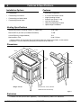
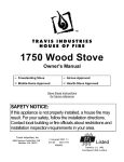
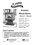
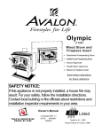
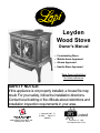
Leyden Wood Stove Owner's Manual • Freestanding Stove • Mobile-Home Approved • Alcove Approved • Hearth-Stove Approved Save these instructions for future reference SAFETY NOTICE: If this appliance is not properly installed, a house fire may result. For your safety, follow the installation directions. Contact local building or fire officials about restrictions and installation inspection requirements in your area. Copyright 2007, T.I. $10.00 100-01177 4060802 4800 Harbour Pointe Blvd. SW Mukilteo, WA 98275 Listed Tested to: U.L. 1482 Test Report # 028-S-75-2 2 Introduction Introduction We welcome you as a new owner of a Leyden wood-burning stove. In purchasing a Leyden you have joined the growing ranks of concerned individuals whose selection of an energy system reflects both a concern for the environment and aesthetics. The Leyden is one of the finest appliances the world over. This manual will explain the installation, operation, and maintenance of this appliance. Please familiarize yourself with the Owner's Manual before operating your appliance and save the manual for future reference. Included are helpful hints and suggestions which will make the installation and operation of your new appliance an easier and more enjoyable experience. We offer our continual support and guidance to help you achieve the maximum benefit and enjoyment from your appliance. Important Information No other Lopi Leyden appliance has the same serial number as yours. The serial number is stamped onto the label on the back of the appliance. Register your warranty online at: This serial number will be needed in case you require service of any type. Or, mail your warranty card to: Model: traviswarranty.com Travis Industries House of Fire 4800 Harbour Pointe Blvd. SW Mukilteo, WA 98275 Lopi Leyden Save Your Bill of Sale. Serial Number: Purchase Date: Purchased From: © Travis Industries To receive full warranty coverage, you will need to show evidence of the date you purchased your heater. Do not mail your Bill of Sale to us. We suggest that you attach your Bill of Sale to this page so that you will have all the information you need in one place should the need for service or information occur. 100-01177 4060802 Table of Contents 3 Operating Your Appliance (continued) General Information Introduction & Important Information...................... 2 Ash Removal.................................................... 24 Safety Precautions ............................................ 4 Ashpan Removal .......................................... 24 Features & Specifications.................................... 6 Blower Operation .............................................. 25 Re-Loading the Stove......................................... 25 Stove Installation Overnight Burn ................................................. 25 Planning the Installation...................................... 7 Normal Operating Sounds ................................... 25 Preparation for Installation .............................. 7 Hints for Burning ............................................... 26 Stove Installation Considerations ..................... 7 Selecting Wood................................................. 26 Floor Protection Requirements ............................. 8 Why Dry Wood is Key.................................... 26 Stove Placement Requirements ........................... 8 Wood Cutting and Storage.............................. 26 Clearances ...................................................... 8 Troubleshooting ................................................ 27 Top View - Straight Installation ........................ 9 Top View - Corner Installation ......................... 9 Maintaining Your Appliance Bypass Handle Installation .................................. 10 Daily Maintenance (while stove is in use) ............... 28 Rear Vent Configuration ..................................... 10 Remove Ash (if necessary) ............................. 28 Chimney Connector Requirments ......................... 11 Clean the Glass (if necessary)......................... 28 Chimney Requirements ...................................... 12 Monthly Maintenance (while appliance is in use) ...... 29 Chimney Termination Requirements...................... 13 Door and Glass Inspection.............................. 29 Outside Air Requirements ................................... 13 Creosote - Formation and Need for Removal...... 29 Alcove Installation Requirements .......................... 14 Yearly Maintenance ........................................... 30 Mobile Home Requirements ................................ 15 Touch Up Paint ............................................ 30 INSTALLATION DIAGRAMS Cleaning the Air Duct and Blower (if applicable) .. 30 Standard Ceiling with a Factory Built Chimney .... 16 Door Parts ....................................................... 31 Cathedral Ceiling with a Factory Built Chimney ... 16 Replacing the Glass ...................................... 31 Hearth Stove Positive Connection .................... 17 Replacing the Door Gasket ............................. 31 Hearth Stove Direct Connection....................... 17 Replacing the Loading Lid Gasket .................... 31 Interior or Exterior Masonry Chimney ................ 18 Replacing the Door Handle ............................. 31 Firebox Parts.................................................... 32 Operating Your Appliance Brick Removal & Replacement ........................ 32 Safety Notice.................................................... 19 Combustor Removal & Replacement ................ 32 Operating the Stove when it is Hot ................... 19 Before Your First Fire ......................................... 19 Warranty Curing the Paint ........................................... 19 Over-Firing the Stove .................................... 19 Warranty ......................................................... 34 Listing Information Opening the Doors ............................................ 20 Listing Information ............................................. 35 Bypass Operation.............................................. 21 Loading Lid Operation ........................................ 21 Optional Equipment Rear Blower Installation ...................................... 36 Starting a Fire................................................... 22 Adjusting the Burn Rate ...................................... 23 Index Approximate Air Control Settings ..................... 23 © Travis Industries 100-01177 Index .............................................................. 38 4060802 4 Safety Precautions The viewing door must be closed and latched during operation. Gas Never block free airflow through the air vents on this appliance. This appliance is designed and approved for the burning of cord wood only. Do not attempt to burn any other type of fuel other than cord wood in this appliance, it will void all warranties and safety listings. Do not touch the appliance while it is hot and educate all children of the danger of a hightemperature appliance. Young children should be supervised when they are in the same room as the appliance. ASHES Inspect the chimney connector and chimney at least twice monthly and clean if necessary. Creosote may build up and cause a house fire. Do not connect this appliance to any chimney serving another appliance. © Travis Industries 100-01177 Ok Type HT Ashes must be disposed in a metal container with a tight lid and placed on a noncombustible surface well away from the home or structure. Keep furniture, drapes, curtains, wood, paper, and other combustibles a minimum of 36" away from the front of the appliance. 36" This appliance must be properly installed to prevent the possibility of a house fire. The instructions must be strictly adhered to. Do not use makeshift methods or compromise in the installation. Gasoline or other flammable liquids must never be used to start the fire or "Freshen Up" the fire. Do not store or use gasoline or other flammable liquids in the vicinity of this appliance. Clay Liner Contact your local building officials to obtain a permit and information on any installation restrictions or inspection requirements in your area. Notify your insurance company of this appliance as well. This appliance must be connected to a listed high temperature (UL 103 HT) residential type chimney or an approved masonry chimney with a standard clay tile, or stainless steel liner. 4060802 Safety Precautions Mobile Home When installed in a mobile home, this appliance must be bolted to the floor, have outside air, and not be installed in the bedroom (Per H.U.D. requirements). Check with local building officials. Never try to repair or replace any part of this appliance unless instructions are given in this manual. All other work must be done by a trained technician. A A A A 5 Do not place clothing or other flammable items on or near this appliance. Do not make any changes or modifications to an existing masonry fireplace or chimney to install this appliance. Do not make any changes to the appliance to increase combustion air. Allow the appliance to cool before carrying out any maintenance or cleaning. Maintain the door and glass seal and keep them in good condition. Overfiring the appliance may cause a house fire. If a unit or chimney connector glows, you are overfiring. Do not use a grate or other device to elevate the fire off of the firebox floor. Burn the fire directly on the bricks. Avoid placing wood against the glass when loading. Do not slam the door or strike the glass. This Manual © Travis Industries Do not throw this manual away. This manual has important operating and maintenance instructions that you will need at a later time. Always follow the instructions in this manual. 100-01177 Travis Industries, Inc. grants no warranty, implied or stated, for the installation or maintenance of your appliance, and assumes no responsibility of any consequential damage(s). 4060802 6 Features & Specifications Installation Options Features • Freestanding • Freestanding in an Alcove • Freestanding in a Mobile Home • Freestanding Hearth Stove • • • • • • • EPA Phase II Approved 2.3 Cubic Foot Firebox Volume Single Operating Control Accepts Logs Up to 21” Long Cast Iron Construction Heavy Duty Refractory Firebrick Optional High-Tech Blower Heating Specifications Approximate Maximum Heating Capacity (in square feet)* Up to 2,000 Maximum BTU's per Hour (Cord Wood Calculation) 73,100 Overall Efficiency (Oregon Method) 70 % Maximum Burn Time Up to 12 Hours * Heating capacity will vary depending on the home's floor plan, degree of insulation, and the outside temperature. It is also affected by the quality and moisture level of the fuel. Dimensions 27-1/4" 22-7/8" 2-5/8" 17" 6-3/4" 28-3/4" 25-1/4" NOTE: Weight: 375 Lbs. Measure side, corner, and back clearances from the stove top. Figure 1 Emissions 2.4 Grams Per Hour (EPA Phase II Approved) – Tests conducted by OMNI-Test Laboratories. © Travis Industries 100-01177 4060802 Stove Installation (for qualified installers only) 7 SAFETY NOTICE: Please read this entire manual before you install and use your new room heater. Failure to follow instructions may result in property damage, bodily injury, or even death. Contact local building or fire officials about restrictions and installation inspection requirements in your area. Always use gloves when operating a hot stove. The door handles, loading lid, bypass handle, and other components become very hot during normal use. Planning The Installation We suggest that you have an authorized Travis Industries dealer install your stove. If you install the stove yourself, your authorized dealer should review your installation plans. Check with local building officials for any permits required for installation of this stove and notify your insurance company before proceeding with installation. Preparation for Installation • Check for damage to the exterior of the stove. • Check the interior of the firebox (replace cracked firebrick and make sure baffle is in place). The stove can be lightened for transportation by removing the doors, loading lid, and firebricks. Replace these components before operation. • Install the bypass handle (included in the owner’s pack - see page 10). Stove Installation Considerations The table below details the six most common types of installations and the considerations for each type. Alternative methods of installation are available if they comply with local building codes. Installation Type Considerations Standard Ceiling with a Factory Built Chimney (Page 16) • • Requires ceiling and roof penetration Provides best draft Cathedral Ceiling with a Factory Built Chimney (Page 16) • • Cathedral style chimney support required Provides best draft Hearth Stove Positive Connection (Page 17) • Utilizes existing masonry fireplace (not approved for zero clearance (metal) fireplaces) Provides good draft due to full reline Easier to clean than direct or horizontal hearth stove Utilizes existing masonry fireplace (not approved for zero clearance (metal) fireplaces) Requires construction of a "block-off plate" Draft reduced due to elbows & chimney cross section Utilizes existing masonry chimney (not approved for zero clearance (metal) fireplaces) Hearth Stove Direct Connection (Page 17) Interior Masonry Chimney (Page 18) © Travis Industries • • • • • • 100-01177 4060802 8 Stove Installation (for qualified installers only) Floor Protection Requirements • Floor protection must extend 6" to the sides and rear of the stove and 16" to the front of the stove 39.25” wide by 44.875" deep - see Figure 2 and Figure 3). • Floor protection must be non-combustible and at least .018" thick (26 guage). Stove Placement Requirements Clearances may be reduced by methods specified in NFPA 211, listed wall shields, pipe shields, or other means approved by local building or fire officials. • Stove must be placed so that no combustibles are within, or can swing within (e.g. drapes, doors), 36" of the front of the stove • Must maintain the clearances to combustibles listed below (drywall, furniture, etc.): Clearances • The following clearances must be met (see Figure 2 and Figure 3) Minimum Clearance Singlewall Connector Singlewall Connector with Pipe Shield** Reduced Clearance* A Sidewall to stove 18.00” 18.00” 18.00” B Backwall to stove 27.25” 17.25” 20.75” C Cornerwall to stove 19.00” 14.00” 14.00” D Connector to sidewall 28.75” 28.75” 28.25” E Connector to backwall 21.00” 11.00” 14.00” F Connector to cornerwall 23.00” 18.00” 17.50” *Reduced clearance installations require one of the chimneys and connectors listed below: AMERI-TEC model DCC connector with AMERI-TEC UL 103 HT chimney DURAVENT model DVL connector with DURAVENT UL 103 HT chimney GSW Super Chimney Twenty-One connected directly to appliance I.C.C. Excel HP connector with I.C.C. UL 103 HT chimney METALFAB model DW connector with METALFAB UL 103 HT chimney OLIVER MACLEOD PROVENT model PV connector with OLIVER MACLEOD UL 103 HT chimney SECURITY model DP connector with SECURITY UL 103 HT chimney SELKIRK model DSP connector with SELKIRK UL 103 HT chimney Standard Masonry Chimney with any one of the above listed connectors NOTE: Reduced clearance connectors may not connect to the flue collar – an appliance adapter may be required. NOTE: Mobile Home installations must use the reduced clearance connector and clearances listed above. NOTE: Standard residential installations with reduced clearance connector may use the “Connector to Wall” clearance determined by the connector manufacturer if approved by local code. This clearance is established by the connector manufacturer and falls under the connector manufacturer’s listing. “Stove to Wall” clearances must always be met. ** The pipe shield must meet NFPA 211 guidelines (such as the HomeSaver® Stovepipe shield) and must extend from the flue collar to a location 16” below the ceiling. © Travis Industries 100-01177 4060802 Stove Installation (for qualified installers only) 9 Minimum Flue Center 31-3/4" Back Wall Clearance B AAAAAAAAAAAAA AAAAAAAAAAAAA AAAAAAAAAAAAA AAAAAAAAAAAAA AAAAAAAAAAAAA AAAAAAAAAAAAA AAAAAAAAAAAAA AAAAAAAAAAAAA AAAAAAAAAAAAA AAAAAAAAAAAAA AAAAAAAAAAAAA AAAAAAAAAAAAA AAAAAAAAAAAAA AAAAAAAAAAAAA AAAAAAAAAAAAA Side Wall Top View Straight Installation Clearance E Typical Flue Center Singlewall 24" Reduced Clearance 17.5" 6” Min. 27-1/4” 2-5/8” Singlewall w Pipe Shield 14" Clearance D 3-1/4” 6” Min. 22-7/8” Clearance A 16” Min. Floor Protection NOTE: vent diameter may vary depending on brand and model. Measure rear and side clearances from the nearest edge of the stove top. Measure front clearances from the face of the stove (door opening). Figure 2 Typical Flue Center Top View Corner Installation Singlewall 26" Reduced Clearance 21" Singlewall w Pipe Shield 21" AAAAAAAAAAAAAA AAAAAAAAAAAAAA AAAAAAAAAAAAAA AAAAAAAAAAAAAA AAAAAAAAAAAAAA AAAAAAAAAAAAAA AAAAAAAAAAAAAA AAAAAAAAAAAAAA AAAAAAAAAAAAAA AAAAAAAAAAAAAA AAAAAAAAAAAAAA AAAAAAAAAAAAAA AAAAAAAAAAAAAA AAAAAAAAAAAAAA AAAAAAAAAAAAAA Clearance F C n or er W l al 27-1/4” 6” Min. Clearance C 2-5/8” C or 3-1/4” ne rW al l 6” Min. 22-7/8” 16” Min. Floor Protection NOTE: vent diameter may vary depending on brand and model. Measure rear and side clearances from the nearest edge of the stove top. Measure front clearances from the face of the stove (door opening). Figure 3 © Travis Industries 100-01177 4060802 10 Stove Installation (for qualified installers only) Bypass Handle Installation See Figure 4 for details on installing the bypass handle. Line up the set screws on the bypass handle with the dimples on the bypass shaft. Tighten with the included 1/8” hex wrench. 1/8" Hex Figure 4 Rear Vent Configuration The rear vent configuration is only for masonry fireplace installations (hearth stove). All steel chimney applications require the top vent configuration. The vent (chimney connector) may be directed to the rear of the appliance when installed into a masonry fireplace. See Figure 5 for details. Open the bypass - this allows for access to the nut under the flue collar. The flue collar is held in place with three bolts and two nuts. Use two 7/16" open-end wrenches to remove the bolts and nuts. 7/16" Wrench Remove the flue collar and rotate it to the rear. Use the existing bolts and nuts to attach the sides of the flue. For the center connection use the bolt and acorn nut included in the owner's pack. NOTE: Make sure the gasket underneath the flue collar is properly located and seals the flue collar when it is installed. Figure 5 © Travis Industries 100-01177 4060802 Stove Installation (for qualified installers only) 11 Chimney Connector Requirements • Chimney connector is required from the flue collar of the stove to the factory-built chimney (see Figure 7) or masonry chimney (see Figures 13, 14, and 15). • The chimney connector must be 6” diameter and a minimum 24 gauge black steel, 26 gauge blued steel, or one of the reduced-clearance connectors listed on page 8. NOTE: Aluminum or galvanized steel is not allowed – these materials can not withstand the flue temperatures and may give off toxic fumes when heated. NOTE: Standard residential installations may use single-wall connector (Mobile-Homes may not). • The chimney connector may not pass through a ceiling, attic, roof, closet, or any other concealed space (use listed UL 103 HT chimney – see “Chimney Requirements for details). DO NOT USE CONNECTOR PIPE AS CHIMNEY. • The chimney connector should be as short and direct as possible. No more than 180 o of elbows (two 90o elbows, or two 45o & one 90o elbow, etc.) may be used for the entire system (connector and chimney).. Horizontal runs should slope upwards 1/4” per foot and be a maximum 36” long. • The chimney connector must be installed with the crimped end pointing downwards (see Figure 7). This prevents creosote from leaking to the exterior of the pipe. • The chimney connector must be fastened to the stove and each adjoining section (and chimney). • In cases where the chimney connector must be passed through a combustible wall or partition, the following NFPA 211 method may be used if local building codes permit. Check with local authorities before installation to insure all necessary requirements have been met. Figure 6 details a wall passthrough based on the NFPA 211 standard. NFPA 211 Wall Pass-Through (see NFPA 211 for a full description) Brick Fire Clay Thimble 12” Min. 12” Min. Combustible Materials Figure 6 © Travis Industries 100-01177 4060802 12 Stove Installation (for qualified installers only) Chimney Requirements • DO NOT CONNECT THIS UNIT TO A CHIMNEY FLUE SERVING ANOTHER APPLIANCE. • UL 103 HT Chimney must be used from the first ceiling or floor penetration to the chimney cap. • Use 6" diameter type UL 103 HT chimney from one manufacturer (do not mix brands) or code approved masonry chimney with a flue liner. • Chimney must be fastened to each adjoining section. • Follow the chimney manufacturer's clearances and requirements. • Use the chimney manufacturer's fire stops, attic guards, roof supports, and flashings when passing through a ceiling • No more than 180o of elbows (two 90o elbows, or two 45o & one 90o elbow, etc.) may be used for the entire system (connector and chimney). NOTE: Additional elbows may be allowed if draft is sufficient. Whenever elbows are used the draft is adversely affected. Additional chimney height may be required to boost draft. AA Chimney Cap (See the section "Chimney Termination Requirements" for more details) A AA } A AA AA AA AA AA AA AA Minimum System 15' Maximum System 33' Roof Penetration Equipment (Roof Radiation Shield, Flashing, Storm Collar) Factory Built Chimney Sections Floor Penetration Equipment (Attic Radiation Shield with Chimney Support) } Minimum Air Space to Combustibles (See Chimney Manufacturer's Instructions - usually 2") } Connector On singlewall pipe the crimped end points downward. Connector Clearance (as outlined in this manual) Floor Protection Drafting Performance AAAAA Figure 7 This appliance relies upon natural draft to operate. External forces, such as wind, barometric pressure, topography, or factors of the home (negative pressure from exhaust fans, chimneys, air infiltration, etc.), may adversely affect draft. Travis Industries can not be responsible for external forces leading to less than optimal performance. © Travis Industries 100-01177 4060802 Stove Installation (for qualified installers only) 13 Chimney Termination Requirements • Must have an approved cap (to prevent water from entering) • Must not be located where it will become plugged by snow or other material • Must terminate at least 3' above the roof and at least 2' above any portion of the roof within 10' (see Figure 8) Slanted Roofs Chimney must extend 3' above the roof Flat Roofs A Chimney must extend 2' above any portion of the roof within 10' of the chimney AA AA AA AA AA Chimney must extend 2' above any portion of the roof within 10' of the chimney A A AAAAAAAAAAAAAAA A Chimney must extend 3' above the roof Figure 8 Outside Air Requirements • Required for mobile homes and in certain localities (check with building officials) • Must not be drawn from an enclosed space (garage, unventilated crawl space) • Requires 3” aluminum duct (do not use plastic “dryer-vent”) and a hose-clamp for securing to the stove. Maximum 4’ length. NOTE: A 10’ length is allowed if using 4” diameter duct (use a 3” to 4” converter). • If using the optional blower, you may need to “ovalize” the duct to route it under the blower box. A screen is required to prevent rodents from entering. Botttom of Stove 3” Air Duct (max. 4’ length) AAAAA Air may be drawn from a ventilated crawl space. Use a hose clamp to secure the AA aluminum air duct to the air inlet flange on the stove. Air Duct (3” Dia.) Outside air entrance must be placed so it does not become blocked by snow. Figure 9 © Travis Industries 100-01177 4060802 14 Stove Installation (for qualified installers only) Alcove Installation Requirements Whenever the stove is placed in a location where the ceiling height is less than 8' tall, it is considered an alcove installation. Because of the reduced height, the special installation requirements listed below must be met. • Chimney connector and chimney must be one of the following types: AMERI-TEC model DCC connector with AMERI-TEC UL 103 HT chimney DURAVENT model DVL connector with DURAVENT UL 103 HT chimney GSW Super Chimney Twenty-One connected directly to appliance I.C.C. Excel HP connector with I.C.C. UL 103 HT chimney METALFAB model DW connector with METALFAB UL 103 HT chimney OLIVER MACLEOD PROVENT model PV connector with OLIVER MACLEOD UL 103 HT chimney SECURITY model DP connector with SECURITY UL 103 HT chimney SELKIRK model DSP connector with SELKIRK UL 103 HT chimney Standard Masonry Chimney with any one of the above listed connectors NOTE: Reduced clearance connectors may not connect to the flue collar – an appliance adapter may be required. • The clearances below must be met: Minimum Clearance (See Figure 10 below) A Sidewall to stove B Backwall to stove D Connector to sidewall E Connector to backwall G Maximum depth of alcove H Minimum width of alcove J Minimum height of alcove Combustible Alcove 18.00" 20.75" 28.25" 14.00" 48.00" 63.25" 84.00" d e a b j h g Figure 10 © Travis Industries 100-01177 4060802 Stove Installation (for qualified installers only) 15 Mobile Home Requirements • Outside air must be installed - see "Outside Air Requirements" on page 13 • Chimney connector and chimney must be one of the following types: AMERI-TEC model DCC connector with AMERI-TEC UL 103 HT chimney DURAVENT model DVL connector with DURAVENT UL 103 HT chimney GSW Super Chimney Twenty-One connected directly to appliance I.C.C. Excel HP connector with I.C.C. UL 103 HT chimney METALFAB model DW connector with METALFAB UL 103 HT chimney OLIVER MACLEOD PROVENT model PV connector with OLIVER MACLEOD UL 103 HT chimney SECURITY model DP connector with SECURITY UL 103 HT chimney SELKIRK model DSP connector with SELKIRK UL 103 HT chimney Standard Masonry Chimney with any one of the above listed connectors NOTE: Reduced clearance connectors may not connect to the flue collar – an appliance adapter may be required. • AAAAAA AAAAAA AAAAAA AAAAAA AAAAAA AAAAAA AAAAAAA AAAAAAA AAAAAAA AAAAAAA AAAAAAA AAAAAAA Stove placement must maintain the following clearances to combustibles (drywall, furniture, etc.) E C B D F A C Measure clearances from the nearest edge of the stove top. Figure 11 Minimum Clearance (See the illustration above) A Sidewall to stove B Backwall to stove C Cornerwall to stove D Connector to sidewall E Connector to backwall F Connector to cornerwall Reduced Clearance Connector 18.00” 20.75” 14.00” 28.25” 14.00” 17.50” • If using offsets, use the connector clearance listed in Figure 12, not the connector manufacturer's clearance. • The appliance must be secured to the floor (consult your building official). Secure the outside air boot to the floor and stove to insure the stove does not dislocate. • Mobile home installations require a spark arrester at the chimney termination. • The appliance must be grounded to the chassis of the mobile home (consult your building official). • WARNING:DO NOT INSTALL IN SLEEPING ROOM. • CAUTION:THE STRUCTURAL INTEGRITY OF THE MOBILE HOME FLOOR, WALL, AND CEILING/ROOF MUST BE MAINTAINED. 12” Min. Connector Clearance (as outlined above) A Stove Clearance (as outlined above) Figure 12 © Travis Industries 100-01177 4060802 16 Standard Ceiling with a Factory Built Chimney AA AA A } A A AA A AA AA AA AA AA } Stove Installation (for qualified installers only) Chimney Cap (See the section "Chimney Termination Requirements" for more details) Chimney Sections Insulation Follow the chimney manufacturer's instructions and clearances for floor penetrations. A ceiling support is required, an attic insulation shield is required where insulation is present. Chimney Connector Sections Floor Protection (See the section "Floor Protection Requirements" for more details) Cathedral Ceiling with a Factory Built Chimney AAAAAA AA AA A A A A} Minimum Air Space to Combustibles (See Chimney Manufacturer's Instructions - usually 2") Minimum 15' Maximum 33' Stove Clearances (See the section "Stove Placement Requirements" for more details) Figure 13 Chimney Cap (See the section "Chimney Termination Requirements" for more details) Chimney Sections Minimum Air Space to Combustibles (See Chimney Manufacturer's Instructions usually 2") Chimney Connector Sections Floor Protection (See the section "Floor Protection Requirements" for more details) © Travis Industries Follow the chimney manufacturer's instructions and clearances for roof penetrations. A storm collar and flashing are required (some require a radiation shield). AAAAAA AAAAAA 100-01177 Follow the chimney manufacturer's instructions and clearances for roof penetrations. A storm collar, flashing, and cathedral-style chimney support are required (some require a radiation shield). Minimum 15' Maximum 33' Stove Clearances (See the section "Stove Placement Requirements" for more details) Figure 14 4060802 Stove Installation (for qualified installers only) Hearth Stove Positive Connection NOTE: Most factory-built chimney manufacturers make stainless steel chimney liners, either flexible or rigid. This provides a wide variety of installation options. Make sure to follow the manufacturer's instructions for installation and support. NOTE: The entire fireplace and chimney must be clean, undamaged, and meet all local building codes (UBC, etc.). Damage must be repaired prior to installation. The chimney must be 15' to 33' tall. Combustible Mantle Min. 36" Floor Protection (See the section "Floor Protection Requirements" for more details) Hearth Stove Direct Connection NOTE: Direct connections require installation of an airtight, non-combustible block-off plate or damper adapter. NOTE: The chimney must have a clay tile liner. If it does not, the installation must use a positive connection (full reline). The entire fireplace and chimney must be clean, undamaged, and meet all local building codes (UBC, etc.). Damage must be repaired prior to installation. The chimney must be 15' to 33' tall. Combustible Mantle Min. 36" Floor Protection (See the section "Floor Protection Requirements" for more details) © Travis Industries 100-01177 AA A A A A AAAA A AAAA A AAAA A AAAA AAAA AAAA AAAA 17 Cap and flashing prevents water from entering The liner must be stainless steel connector or flexible vent. Follow the liner manufacturer's instructions for installation and support. Airtight Insulated Clean-Out Remove damper or wire it open See the section "Stove Placement Requirements" for minimum clearances required. Figure 15 Clay Liner A A A AAA A AAA A AAA AAA AAA AAA AAA Stainless steel chimney connector must Extend 1' past the block-off plate or to the flue liner Airtight Insulated Clean-Out Remove damper or wire it open Block-off plate or damper adapter See the section "Stove Placement Requirements" for minimum clearances required. Figure 16 4060802 18 Stove Installation (for qualified installers only) Interior or Exterior Masonry Chimney NOTE: This type of installation requires a UBC approved masonry connector or other method approved by the NFPA 211 standard. See Chimney Connector Requirements on page 11 for further details. NOTE: The chimney must have a clay tile liner. If it does not, the installation must use a positive connection (full reline). The entire fireplace and chimney must be clean, undamaged, and meet all local building codes (UBC, etc.). Damage must be repaired prior to installation. The chimney must be 15' to 33' tall. Clay Liner Min. 18" clearance to ceiling See the section "Stove Placement Requirements" for minimum clearances required. Chimney connector sections This type of installation requires a UBC approved masonry connector or other method approved by the NFPA 211 standard. Full Re-Line (recommended) Make sure the clean-out seals in place. See the section "Floor Protection Requirements" Figure 17 © Travis Industries 100-01177 4060802 Operating Your Appliance 19 Safety Notice If this appliance is not properly installed, a house fire may result. For your safety, follow the installation directions. Contact local building or fire officials about restrictions and installation inspection requirements in your area. Read and follow all of the warnings on pages 4 and 5 of this manual. Operating the Stove when it is Hot Always use gloves when operating a hot stove. The door handles, loading lid, bypass handle, and other components become very hot during normal use. Before Your First Fire AAAA AAAA AAAA AAAA AAAA AAAA Verify the Installation Before starting the stove, verify that the stove is properly installed and all of the requirements in this manual have been followed. Keep all flammable materials 36" away from the front of the stove (drapes, furniture, clothing, etc.). Curing the Paint 2 to 4 hours This heater uses a heat-activated paint that will emit some fumes while starting the first fire. Open doors and windows to the room to vent these fumes. This typically lasts two to four hours. You may also notice oil burning off of the interior of the heater. This rust-stopping agent will soon dissipate. Furthermore, do not burn the stove at a high temperature during the first fire. This allows the cast iron and finish to properly cure. A A AAA A Door Gasket - The door gasket might adhere to the paint on the front of the heater. Leave the door slightly ajar for the first fire and be careful when opening the door after the first fire. Over-Firing the Stove This stove was designed to operate at a high temperature. But due to differences in vent configuration, fuel, and draft, this appliance can be operated at an excessive temperature. If the stove top or other area starts to glow red, you are over-firing the stove. Shut the air control down to low and allow the stove to cool before proceeding. Over-firing may lead to damage of plated surfaces. If you are uncertain of over-firing conditions, we suggest placing a stove thermometer (e.g. Rutland® Model 710) directly over the door on the stove top temperatures exceeding 800° are generally considered over-firing and will void the warranty. © Travis Industries 100-01177 4060802 20 Operating Your Appliance Opening the Doors Typically the doors are only opened to start the fire. Use the Loading Lid to re-load the stove. Open the bypass first (this prevents smoke from entering the room). A door latch tool is included for operation when the door latch is hot. Hang the tool on the air control when not in use. Open the latch. Swing the doors open. WARNING: Do not swing the doors past 90°. This may cause the doors to strike the body of the stove and cause damage. NOTE: When closing the doors, close the left door first. Then shut the right door and tighten the latch. The door becomes hot during use. Use a glove to open the door if the handle is hot. To prevent smoke from entering the room, open the bypass before opening the door (see following page for directions). You can also open the door a small amount and let air enter the firebox. © Travis Industries 100-01177 4060802 Operating Your Appliance 21 Bypass Operation The bypass controls the flow of smoke inside the heater. When open, smoke goes directly up the flue, creating more draft. When closed, the smoke goes through the combustor, utilizing the secondary combustion system and making the heater more efficient. • When starting or re-loading the stove, open the bypass. • Once the stove reaches full temperature – typically 30 minutes, close the bypass. The bypass handle is located on the left side. Rotate it to open the bypass. Bypass OPEN Used for starting and re-loading Bypass CLOSED Used for normal operation AAAAA AAAAA AAAAA AAAAA AAAAA AA AAAA AAA AAA If the bypass does not latch in the closed position, you will need to adjust the bypass latch (see page 30). Loading Lid Operation b Open the bypass first (this helps prevent smoke from entering the room). c Open the lid 1" for a few seconds to allow air to enter the firebox. d Lift the lid upward. WARNING: This part becomes hot - use gloves. a A log poker is provided with this stove. It attaches with a clip to to the back of the stove. Open the air control and allow air to flow into the firebox for 30 seconds. Do not wear loose clothing while re-loading the stove. Any item dangling above the opening may ignite. Carefully close the loading lid after use. Allowing it to “slam” shut may damage the stove. © Travis Industries 100-01177 4060802 22 Operating Your Appliance Starting a Fire Since the dawn of time man has debated the best way to start a fire. Some use the boy-scout "tee-pee", some prefer the "tic-tac-toe" stack. Either way, review the hints and warnings below to ensure proper fire starting. • Make sure the air control and by-pass are pulled out. If additional air is needed, open the doors 1/4" during the first five minutes of start-up. Open the bypass. Leave it open until the stove is HOT (up to 45 minutes). Pull the air control all the way out. ALLOW THE STOVE TO FULLY HEAT PRIOR TO SHUTTING THE BYPASS We occasionally get calls regarding a smokey stove during start-up. The primary cause is shutting the bypass prior to the stove becoming hot. If you shut the bypass too early, the combustor will not work (the combustor must be hot for it to work properly). This in turn will slow combustion and will lead to a smokey fire. Never use gasoline, gasoline-type lantern fuel, kerosene, charcoal lighter fluid, or similar liquids to start or "freshen up" a fire in this stove. Keep all such liquids well away from the stove while it is in use. If using a firestarter, use only products specifically designed for stoves - follow the manufacturer's instructions carefully. If the smoke does not pass up the chimney, ball up one sheet of newspaper, place it in the center of the firebox and light it. This should start the chimney drafting (this eliminates "cold air blockage"). Use plenty of kindling to ensure the stove reaches a proper temperature. Once the kindling is burning rapidly, place a few larger pieces of wood onto the fire. Starting a “Top-Down Fire” One particularly successful method for starting a fire is to stack several large pieces of wood in the center of the stove (see the illustration to the right). Then place a several wads of newspaper in the center with kindling on top. When you light the newspaper this “top-down” fire will burn its way to the center, igniting the larger pieces. With some practice, this method should work for you. © Travis Industries 100-01177 4060802 Operating Your Appliance 23 Adjusting the Burn Rate Use the air control slider to control the burn rate of the stove. See the illustration below for details. Use the air control to change the burn rate. AAA AAA Low Burn High Burn (air control closed) (air control open) Approximate Air Control Settings Overnight Burn Fully in Medium Burn 1/32" to 5/32” Open Medium High Burn 5/32” to Fully Open High Burn Fully Open (Pulled Out) The air control becomes hot during operation - use gloves or a tool to prevent burns. The air control may take several minutes to influence the burn rate. When making adjustments, you may wish to let the stove burn for 10 minutes to gauge performance. © Travis Industries 100-01177 4060802 24 Operating Your Appliance Ash Removal ASHES Ashes should be placed in a metal container with a tight fitting lid. The closed container of ashes should be placed on a noncombustible floor or on the ground, away from all combustible materials, pending final disposal. If the ashes are disposed of by burial in soil or otherwise locally dispersed, they should be retained in the closed container until all cinders have thoroughly cooled. Ashpan Removal The ashpan must be properly inserted and fully closed during operation. Failure to fully close and seal the ashpan may lead to an over-fired stove, negating the warranty and creating a safety hazard. The ashpan may only be removed after the stove has fully cooled. Lift up on the ashlip and slide the ashpan AAAAA AAAAA AAAAA AA Twist the ashpan handle clockwise. forward. AA AA A handle is provided on the ashpan to remove the ashes. AA AAAAA AA AAAAA AAAAA AAAAA AA AA © Travis Industries 100-01177 4060802 Operating Your Appliance 25 Blower Operation The blower is available to assist the convection chamber in distributing heat to your home. The directions below detail the options you have with the blower and the best method for operation. OFF HIGH LOW Turn the dial all the way counter- The high position is all the way counter- Turn the dial all the clockwise until it clicks off. clockwise, without clicking off. way clockwise. AA A A A AA AA A START OFF RUN BLOWER CONTROL AAAA AAAA AA START OFF BLOWER CONTROL AA A AA AA AA AA AAA START OFF RUN RUN BLOWER CONTROL Route the power cord in a location where it will not come in contact with the appliance or become hot. Re-Loading the Stove Follow the directions below to minimize smoke spillage while re-loading the stove. 1 Open the air control all the way (pull it out). Open the bypass (rotate it down). 2 Open the loading lid. Let the airflow inside the firebox stabilize before opening the loading lid fully. 3 Load wood onto the fire. Overnight Burn This stove is large enough to accommodate burn times up to twelve hours. Follow the steps below to achieve an overnight burn. 1 Move the air control to high burn and let the stove become hot (burn for approximately 15 minutes). 2 Load as much wood as possible. Use large pieces if possible. 3 Let the stove burn on high for 15 minutes to keep the stove hot, then turn the air control to low. 4 In the morning the stove should still be hot, with embers in the coal bed. Stir the coals and load small pieces of wood to re-ignite the fire, if desired. Differences if chimney height and draft may lower overall burn times. Normal Operating Sounds Creaks and Clicks: The steel may creak or click when the stove heats up and cools down - this is normal. Blower Sounds: The optional blower will make a slight "humm" as it pushes air through the stove. © Travis Industries 100-01177 4060802 26 Operating Your Appliance Hints for Burning • Get the appliance hot before adjusting to low burn • Use smaller pieces of wood during start-up and high burns to increase temperature • Use larger pieces of wood for overnight or sustained burns • Stack the wood tightly together to establish a longer burn • Leave a bed of ashes (1/2" deep) to allow for longer burns • Be considerate of neighbors & the environment: burn dry wood only • Burn small, intense fires instead of large, slow burning fires when possible • Learn your appliance's operating characteristics to obtain optimum performance Selecting Wood • Dry Wood is Key • Dry wood burns hot, emits less smoke and creates less creosote. • Testing Wood Moisture • Split wood stored in a dry area will be fully dry within a year. This insures dry wood. If purchasing wood for immediate use, test the wood with a moisture meter. Some experienced wood burners can measure wood moisture by knocking pieces together and listening for a clear "knock" and not a "thud". Wet Wood Dry Wood Leads To Leads To Less Heat More Heat Leads To Leads To More Smoke and Creostoe Less Smoke and Creostoe Why Dry Wood is Key Wet wood, when burned, must release water stored within the wood. This cools the fire, creates creosote, and hampers a complete burn. Ask any experienced wood burner and he or she will agree: dry wood is crucial to good performance. Wood Cutting and Storage Cut wood to length and chop into quarters. Store the wood off the ground in a covered area. Allow for airflow around the wood to dry the wood. Air Flow Air Flow Air Flow © Travis Industries 100-01177 4060802 Operating Your Appliance 27 Troubleshooting Problem Possible Cause Smoke Enters Room During Start-Up • Open the bypass (pg. 21). • Open the air control (pg. 23). • Cold Air Blockage - burn a piece of newspaper to establish a draft. • If the flame is not getting enough air, a small crack in the door is all that is needed. • Open the bypass (pg. 21). • Open the air control (pg. 23). • Not enough starter paper - use additional newspaper if necessary. • If the flame is not getting enough air, a small crack in the door is all that is needed. • Open the bypass before opening the door (pg. 21). • Open the air control before opening the door (pg. 23). • Open the loading lid 1 inch and let air enter the firebox for a few seconds. Once the smoke appears to be flowing up the chimney consistently, open the loading lid completely. • Insufficient Draft - Chimney height and outside conditions can negatively affect draft. In these cases a small amount of smoke may enter the home. Adding more pipe or a draft-inducing cap may help. Kindling Does Not Start - Fire Smolders Smoke Enters Room While ReLoading Stove Does Not Burn Hot Enough • Blower Does Not Run Stove Does Not Burn Long Enough © Travis Industries Wood is Wet - see the section "Selecting Wood" on page 26 for details on wood. • Make sure the air control is all the way open. Slide the control back and forth to insure the control is not stuck. • Insufficient Draft - Chimney height and outside conditions can negatively affect draft. In these cases the fire may burn slowly. Adding more pipe or a draftinducing cap may help. • Stove is Not Up to Temperature - This is normal. The blower will come on when the stove is hot - usually 15 to 30 minutes. • Electricity is Cut to the Blower - Check the household breaker or fuse to make sure it is operable. • Depending upon wood, draft, and other factors, the burn time may be shorter then stated. Make sure the doors are sealing and not allowing air into the firebox See the section "Door and Glass Inspection" on page 29 for details. • Check the ash bed for coals. Often, coals are still glowing under a slight bed of flyash. By raking these into a pile you can re-start your stove quickly. 100-01177 4060802 28 Maintaining Your Appliance Failure to properly maintain and inspect your appliance may reduce the performance and life of the appliance, void your warranty, and create a fire hazard. Daily Maintenance (while stove is in use) Remove Ash (if necessary) • Ash removal is not required once it builds up. 1/2" to 1" of ash may be desirable because it slows the burn rate. Generally, remove ash once it has built up over 1". Follow the directions below to remove ash. 1 Let the stove cool completely (at least two hours after the last coal has extinguished). 2 Direct all of the ash through the grill into the ashpan. Remove the ashpan (see page 24). Place the ash into a metal container with a tight fitting lid. The closed container of ashes should be placed on a noncombustible floor or on the ground, away from all combustible materials, pending final disposal. 3 ASHES You may wish to remove any ash that is deposited in the combustion brick or combustor (see page 32). This will insure proper combustor operation. Improperly disposed ashes lead to fires. Hot ashes placed in cardboard boxes, dumped in back yards, or stored in garages, are recipes for disaster. Wood-burning stoves are inherently dirty. During cleaning have a vacuum ready to catch spilled ash (make sure ash is entirely extinguished). There are vacuum cleaners specifically made to remove ash (even if the ash is warm). Contact your dealer for details. Clean the Glass (if necessary) This appliance has an airwash to keep the glass clean. However, burning un-seasoned wood or burning on lower burn rates leads to dirtier glass (especially on the sides). Clean the glass by following the directions below. Allow the stove to fully cool. Apply glass cleaner or soapy water to the inside of the glass. Wipe with newspaper or a paper towel. AA AA For Stubborn Creosote: Dip newspaper or a paper towel in cool ashes and wipe it on the glass. The ash acts as a light abrasive. AAA The glass will develop a very slight haze over time. This is normal and will not affect viewing of the fire. © Travis Industries 100-01177 4060802 Maintaining Your Appliance 29 Monthly Maintenance (while appliance is in use) Make sure the appliance has fully cooled prior to conducting service. Door and Glass Inspection The door must form an air-tight seal to the firebox for the stove to work correctly. Inspect the door gasket to make sure it forms an air-tight seal to the firebox. The door can be lifted off the hinges if extensive repairs are conducted. High-Temperature anti-sieze may be used on the door hinges to eliminate squeaks. AAAA AAAA AAAA AAAA AAAA AAAA AAAA Use wood stove gasket cement to re-adhere loose gasket. Severely frayed or thread-bare gasket should be replaced. If the glass is damaged, replace it - see “Replacement Parts” for details. The door latch should pull the door against the face of the stove (but not so tight as to not allow full handle rotation). To adjust the door latch, adjust the position of the striker plate that attaches to the front plate of the stove. Creosote - Formation and Need for Removal When wood is burned slowly, it produces tar and other organic vapors, which combine with expelled moisture to form creosote. The creosote vapors condense in the relatively cool chimney flue of a slowburning fire. As a result, creosote residue accumulates on the flue lining. When ignited, this creosote makes an extremely hot fire. The chimney and chimney connector should be inspected at least once every two months during the heating season to determine if a creosote buildup has occurred. If creosote has accumulated, it should be removed to reduce the risk of a chimney fire. If you are not certain of creosote inspection, contact your dealer or local chimney sweep for a full inspection. Excess creosote buildup may cause a chimney fire, that may result in property damage, injury, or death. © Travis Industries 100-01177 4060802 30 Maintaining Your Appliance Yearly Maintenance Make sure the appliance has fully cooled prior to conducting service. Touch Up Paint Included with the owner's pack of this appliance is a can of Stove-Brite® paint. To touch up nicks or dulled paint, apply the paint while the appliance is cool. Sand rusted or damaged areas before preparation (use 120 grit sandpaper). Clean and dry the area to prepare the surface. Wait at least one hour before starting the appliance. The touched up area will appear darker than the surrounding paint until it cures from heat. Curing will give off some fumes while curing – open windows to ventilate. Touch-Up Paint Cleaning the Air Duct and Blower (if applicable) Use a vacuum to clean the air ducts (channels). This prevents dust from burning and creating odors. The optional blower should be vacuumed every year to remove any buildup of dust, lint, etc. BOTTOM OF STOVE Use a vacuum cleaner to remove any buildup on the screens of the blower. Adjusting the Bypass Latch The bypass latch uses a pressure plate to secure it in the closed position. If the bypass does not latch to the closed position, it may be adjusted following the directions below. Close the bypass -- you may need to hold it in the shut position. Bypass Plate 7/16" Wrench Tighten this bolt 1/2 turn. Test operation of the bypass - opening and closing it several times. If it does not latch shut, tighten the bolt another 1/2 turn. NOTE: In rare cases the bolt may be over-tightened, not allowing the bypass handle to rotate down. in these cases, loosen the bolt. Verify Cast Iron Fasteners Verify the fasteners holding the cast iron components are properly tightened. © Travis Industries 100-01177 4060802 Maintaining Your Appliance 31 Door Parts AAA AAA AAA AAA AAA AAA AAA AAA AAA AAA AAA AAA AAA AAA AAAAAA AAA AAA AAA 4 3 1 8 9 6 5 7 2 10 ID # 1 3 5 7 9 Description Door, Left Door Gasket Glass Gasket Glass Clip w Screws, Gasket Left Door Handle w Hardware Qty 1 1 1 4 1 Part # ID # 2 4 6 8 10 Description Door, Right Gasket Cement Glass Door Hinge w Pins Right Door Handle w Hardware Qty 1 1 2 4 1 Part # Replacing the Glass The glass must not contact the door retainer or glass clips directly. The glass gasket and glass clip gaskets insulate the glass to prevent cracking. Do not over-tighten the glass clips. Replacing the Door Gasket The door gasket inserts into the outer groove of the door. Stove gasket cement holds it in place. Before installing, remove any residual cement. Lay the gasket in place (start at the lower left corner) and cut off any excess gasket (do not stretch the gasket. The cement fully cures with heat from the stove. You may need to open and close the door repeatedly to get the gasket to seat fully. Replacing the Loading Lid Gasket The loading lid gasket inserts into the groove below the loading lid. Stove gasket cement holds it in place. Before installing, remove any residual cement. Lay the gasket in place (start at the back left corner) and cut off any excess gasket (do not stretch the gasket. The cement fully cures with heat from the stove. You may need to open and close the lid repeatedly to get the gasket to seat fully. Replacing the Door Handle See the illustration above for a component list (see pg. 29 for details on adjusting the door). © Travis Industries 100-01177 4060802 32 Maintaining Your Appliance Firebox Parts 7 6 5 7 4 1 AAAAAAAA AAAAAAAA AAAAAAAA AAAAAAAA AAAAAAAA 3 2 9 8 1 ID # 1 3 5 7 9 Description Side Brick Interram Gasket Firebox Back Brick Clips with Bolts Firebox Back Screw Qty 2 1 1 1 4 Part # 250-00139 250-00294 250-00144 ID # 2 4 6 8 Description Combustion Brick Back Brick Combustor Combustion Brick Gasket Qty 1 1 1 1 3 Part # 250-00141 250-00140 250-00247 Brick Removal & Replacement Do not pry brick - they chip and crack easily. Remove the clips holding the side brick in place. Remove the side brick. Remove the clip holding the back brick in place. Lift the back brick up and remove. Remove the gasket on top of the combustion brick. Remove the combustion brick. Combustor Removal & Replacement Remove the bricks first. Remove the rear heat shield (the screws holding the firebox back are held in place with nuts accessible from the back of the stove). Remove the firebox back (use a wrench to secure the nuts on the back of the stove will un-screwing the 4 screws holding the firebox back in place). Remove the bypass assembly (two nuts and two bolts hold it in place – take care when removing to prevent damage). Slide the combustor forward to remove. © Travis Industries 100-01177 4060802 Limited 5 Year Warranty 33 To register your TRAVIS INDUSTRIES, INC. 5 Year Warranty, complete the enclosed warranty card and mail it within ten (10) days of the appliance purchase date to: TRAVIS INDUSTRIES, INC., 4800 Harbour Pointe Blvd. SW, Mukilteo, WA 98275. TRAVIS INDUSTRIES, INC. warrants this appliance (appliance is defined as the equipment manufactured by Travis Industries, Inc.) to be defect-free in material and workmanship to the original purchaser from the date of purchase as follows: Check with your dealer in advance for any costs to you when arranging a warranty call. Mileage or service charges are not covered by this warranty. This charge can vary from store to store. Year1 - COVERAGE: PARTS & LABOR Cast Iron Parts Accessories Warranted against breakage, cracking, or burn through. Enamel Finish Blower Damper Bypass Assembly Warranted against peeling or fading, excluding chipping, mechanical abrasion, or crazing. Combustion System Bypass plate, rod, handle Door Handles and Latching Mechanism Door handle, shaft, cam, hardware Firebrick, combustor - Warranted against breakage or deterioration not resulting from physical damage or overloading of the wood stove. Re-Installation Allowance In cases where heater must be removed from home for repairs, a partial cost of re-installation is covered (pre-authorization required) Air Control Assembly Slider Plate, Pressure Plate One-Way Freight Allowance Ceramic Glass One-way freight allowance on pre-authorized repair done at factory is covered. Glass (breakage from thermal shock) Ash Removal System Cement and Gasketing Ashpan, rollers, grate. Exclusions: Paint Years 2 & 3 - COVERAGE: PARTS & LABOR Cast Iron Parts Damper Bypass Assembly Warranted against breakage, cracking, or burn through. Combustion System Bypass plate, rod, handle Door Handles and Latching Mechanism Firebrick, combustor - Warranted against breakage or deterioration not resulting from physical damage or overloading of the wood stove. Door handle, shaft, cam, hardware Re-Installation Allowance In cases where heater must be removed from home for repairs, a partial cost of re-installation is covered (pre-authorization required) Air Control Assembly Slider Plate, Pressure Plate Ash Removal System One-Way Freight Allowance Ashpan, rollers, grate. Exclusions: One-way freight allowance on pre-authorized repair done at factory is covered. Paint, Enamel Finish, Cement and Gasketing, Ceramic Glass, Accessories, Years 4 & 5 - COVERAGE: PARTS & LABOR Air Control Assembly Damper Bypass Assembly Slider Plate, Pressure Plate Bypass plate, rod, handle Ash Removal System Door Handles and Latching Mechanism Ashpan, rollers, grate. Exclusions: Door handle, shaft, cam, hardware Paint, Enamel Finish, Cement and Gasketing, Ceramic Glass, Accessories, Re-Installation Allowance, One-Way Freight Allowance, Cast Iron Parts, Combustion System Page 1 of 2 © Travis Industries 100-01177 4060802 34 Limited 5 Year Warranty CONDITIONS & EXCLUSIONS 1. This new appliance must be installed by a qualified installer. It must be installed, operated, and maintained at all times in accordance with the instructions in the Owner’s Manual. Any alteration, willful abuse, accident, neglect, or misuse of the product shall nullify this warranty. 2. This warranty is nontransferable, and is made to the ORIGINAL purchaser, provided that the purchase was made through an authorized Travis dealer. 3. Discoloration and some minor expansion, contraction, or movement of certain parts and resulting noise, is normal and not a defect and, therefore, not covered under warranty. 4. This warranty does not cover misuse of the stove. Misuse includes over-firing (operation where the connector or stove may glow red) of this appliance can cause serious damage and will nullify this warranty. Misuse includes use of salt saturated wood, chemically treated wood, or any fuel not recommended in the manual. 5. Damage to the stove due to improper break-in procedures (see manual for proper break in). 6. The salt air environment of coastal areas or a high humidity environment can be corrosive to the castings. These conditions can be corrosive and can cause the cast iron to rust. This warranty does not cover any damage caused by a salt air or high humidity environment. 7. Damage to the appliance while it is in transit is not covered by this warranty, but is subject to a claim against the common carrier. 8. The warranty, as outlined within this document, does not apply to the chimney components or other Non-Travis accessories used in conjunction with the installation of this product. If in doubt as to the extent of this warranty, contact your authorized Travis retailer before installation. 9. Travis Industries will not be responsible for inadequate performance caused by environmental conditions such as nearby trees, buildings, roof tops, wind, hills or mountains or negative pressure or other influences from mechanical systems such as furnaces, fans, clothes dryers, etc. 10. This Warranty is void if: a. The appliance has been operated in atmospheres contaminated by chlorine, fluorine or other damaging chemicals. b. The appliance is subject to submersion in water or prolonged periods of dampness or condensation. c. Any damage to the appliance, combustion chamber, heat exchanger or other components due to water, or weather damage which is the result of, but not limited to, improper chimney/venting installation. 11. Exclusions to this 5 Year Warranty include: injury, loss of use, damage, failure to function due to accident, negligence, misuse, improper installation, alteration or adjustment of the manufacturer's settings of components, lack of proper and regular maintenance, damage incurred while the appliance is in transit, alteration, or act of God. 12. This 5 Year warranty excludes damage caused by normal wear and tear, such as paint discoloration or chipping, worn or torn gasketing, chipped or cracked firebrick, etc. Also excluded is damage to the appliance caused by abuse, improper installation, modification of the appliance, or the use of fuel other than that for which the appliance is configured (use cord wood only). 13. Damage to brass or plated surfaces caused by fingerprints, scratches, melted items, or other external sources left on the surfaces from the use of abrasive cleaners is not covered in this warranty. Damage to the surfaces from over-firing (operation where the steel may glow red) is not covered in this warranty. 14. TRAVIS INDUSTRIES, INC. is free of liability for any damages caused by the appliance, as well as inconvenience expenses and materials. Incidental or consequential damages are not covered by this warranty. In some states, the exclusion of incidental or consequential damage may not apply. 15. This warranty does not cover any loss or damage incurred by the use or removal of any component or apparatus to or from the Travis appliance without the express written permission of TRAVIS INDUSTRIES, INC. and bearing a TRAVIS INDUSTRIES, INC. label of approval. This warranty does not cover a stove repaired by someone other than a Travis Industries authorized dealer. 16. Any statement or representation of Travis products and their performance contained in Travis advertising, packaging literature, or printed material is not part of this 5 year warranty. 17. This warranty is automatically voided if the appliance’s serial number has been removed or altered in any way. If the appliance is used for commercial purposes, it is excluded from this warranty. 18. No dealer, distributor, or similar person has the authority to represent or warrant Travis products beyond the terms contained within this warranty. TRAVIS INDUSTRIES, INC. assumes no liability for such warranties or representations. 19. Travis Industries will not cover the cost of the removal or re-installation of hearths, facing, mantels, venting or other components. 20. If for any reason any section of this warranty is declared invalid, the balance of the warranty remains in effect and all other clauses shall remain in effect. 21. This 5 year warranty is the only warranty supplied by Travis Industries, Inc., the manufacturer of the appliance. All other warranties, whether express or implied, are hereby expressly disclaimed and purchaser’s recourse is expressly limited to the warranties set forth herein. IF WARRANTY SERVICE IS NEEDED: 1. If you discover a problem that you believe is covered by this warranty, you MUST REPORT it to your Travis dealer WITHIN 30 DAYS, giving them proof of purchase, the purchase date, and the model name and serial number. 2. Travis Industries has the option of either repairing or replacing the defective component. 3. If your dealer is unable to repair your appliance’s defect, he may process a warranty claim through TRAVIS INDUSTRIES, INC., including the name of the dealership where you purchased the appliance, a copy of your receipt showing the date of the appliance’s purchase, and the serial number on your appliance. At that time, you may be asked to ship your appliance, freight charges prepaid, to TRAVIS INDUSTRIES, INC. TRAVIS INDUSTRIES, INC., at its option, will repair or replace, free of charge, your appliance if it is found to be defective in material or workmanship within the time frame stated within this 5 year warranty. TRAVIS INDUSTRIES, INC. will return your appliance, freight charges (years 1 to 3) prepaid by TRAVIS INDUSTRIES, INC., to your regional distributor, or dealership. 4. Check with your dealer in advance for any costs to you when arranging a warranty call. Mileage or service charges are not covered by this warranty. This charge can vary from store to store. 5. Any appliance or part thereof that is repaired or replaced during the limited warranty period will be warranted under the terms of the limited warranty for a period not to exceed the remaining term of the original limited warranty or six(6) months, whichever is longer. Page 2 of 2 © Travis Industries 100-01177 4060802 Listing Information 35 Listing Label © Travis Industries 100-01177 4060802 36 Optional Equipment Rear Blower Installation (Part # 99000138) The rear blower improves heat transfer by pushing heated air through the convection channel. Operating instructions are described in the section "Blower Operation". a Bend the legs of the thermodisk bracket to b make it 1-1/2” deep. Tuck the thermodisk into place. It 1-1/2” wedges between the rear heat sheild and the cast iron firebox. c Route the wires on the outside of the stove, behind the convection jacket. d Route the wires from the blower through the hole in the back of the blower housing. Attach these wires to the thermodisk wires. 3/8" Wrench f Attach the blower to the stove with the three screws included with the blower. e Position the blower near the rear of the stove. Tuck all excess wire into the blower box, making sure it does not contact any moving parts. Make sure when installing the blower, these wires do not become loose. g Plug the blower in. Do not route the power cord under or over the stove or in a location where it may become damaged. © Travis Industries 100-01177 4060802 37 © Travis Industries Optional Equipment 100-01177 4060802 38 Index Air Control (Adjusting the Burn Rate) .......................23 Hearth Stove Positive Connection .......................... 17 Alcove Installation Requirements ............................14 Hints for Burning................................................. 26 Ash Removal......................................................24 Interior or Exterior Masonry Chimney ...................... 18 Ash Removal......................................................28 Introduction & Important Information ....................... 2 Ashpan .............................................................24 Listing Information .............................................. 35 Blower Cleaning (if applicable) ...............................30 Loading (Re-Loading the Stove) ............................ 25 Blower Installation ...............................................36 Loading Lid Gasket Replacement........................... 31 Blower Operation ................................................25 Loading Lid Operation ......................................... 21 Brick Removal & Replacement ...............................32 Mobile Home Requirements.................................. 15 Burn Rate ..........................................................23 Monthly Maintenance (while appliance is in use) ....... 29 Bypass Operation................................................21 Opening the Doors.............................................. 20 Cathedral Ceiling with a Factory Built Chimney..........16 Operating the Stove when it is Hot ......................... 19 Chimney Connector Requirments ...........................11 Outside Air Requirements..................................... 13 Chimney Requirements ........................................12 Over-Firing the Stove .......................................... 19 Chimney Termination Requirements........................13 Overnight Burn................................................... 25 Clearances ........................................................8 Paint (Touch Up Paint)......................................... 30 Combustor Removal & Replacement .......................32 Paint Smell (Curing the Paint) ............................... 19 Corner Installation (Top View) ................................9 Planning the Installation ....................................... 7 Creosote - Formation and Need for Removal ............29 Preparation for Installation .................................... 7 Curing the Paint ..................................................19 Rear Vent Configuration....................................... 10 Daily Maintenance (while stove is in use) .................28 Safety Label ...................................................... 35 Damper (Bypass Operation) ..................................21 Safety Precautions.............................................. 4 Door and Glass Inspection ....................................29 Sounds............................................................. 25 Door Gasket Replacement ....................................31 Specifications .................................................... 6 Door Handle Replacement ....................................31 Standard Ceiling with a Factory Built Chimney .......... 16 Door Parts .........................................................31 Starting a Fire .................................................... 22 Doors (Opening the Doors)....................................20 Stove Installation Considerations ........................... 7 Features & Specifications......................................6 Stove Placement Requirements............................. 8 Firebox Parts......................................................32 Top View - Corner Installation ............................... 9 First Fire............................................................19 Top View - Straight Installation .............................. 9 Floor Protection Requirements ...............................8 Troubleshooting ................................................. 27 Glass Cleaning ...................................................28 Warnings (Safety Precautions) .............................. 4 Glass Replacement .............................................31 Warranty........................................................... 34 Hearth (Floor Protection Requirements) ...................8 Wood (Selecting Wood) ....................................... 26 Hearth Stove Direct Connection .............................17 Yearly Maintenance ............................................ 30 © Travis Industries 100-01177 4060802