1
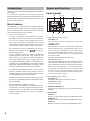
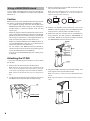
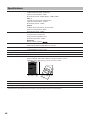
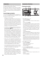
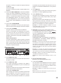
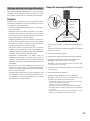
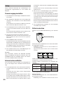
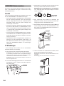
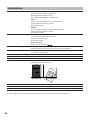
1
English
Introduction..........................................................................................4
Names and Functions..........................................................................4
Setting Up............................................................................................6
Attaching the stabilizer.........................................................................7
Using a WAVEDRUM stand.................................................................8
Using a speaker stand.........................................................................9
Specifications.....................................................................................10
Français
Introduction........................................................................................12
Commandes et fonctions...................................................................12
Prise en main.....................................................................................14
Montage du stabilisateur....................................................................15
Montage d’un stand WAVEDRUM.....................................................16
Montage du retour sur un pied d’enceinte.........................................17
Fiche technique.................................................................................18
Deutsch
Einleitung...........................................................................................20
Bedienelemente und deren Funktionen.............................................20
Set-up................................................................................................22
Stabilisator anbringen........................................................................23
WAVEDRUM-Ständer einsetzen........................................................24
Monitorstativ einsetzen......................................................................25
Technische Daten..............................................................................26
IMPORTANT SAFETY INSTRUCTIONS
•
•
•
•
•
•
•
•
•
•
•
•
•
•
•
•
•
•
•
•
•
•
Read these instructions.
Keep these instructions.
Heed all warnings.
Follow all instructions.
Do not use this apparatus near water.
Mains powered apparatus shall not be exposed to dripping or splashing and that no objects filled with liquids, such as vases, shall be
placed on the apparatus.
Clean only with dry cloth.
Do not block any ventilation openings. Install in accordance with the
manufacturer’s instructions.
Do not install near any heat sources such as radiators, heat registers,
stoves, or other apparatus (including amplifiers) that produce heat.
Do not defeat the safety purpose of the polarized or grounding-type
plug. A polarized plug has two blades with one wider than the other.
A grounding type plug has two blades and a third grounding prong.
The wide blade or the third prong are provided for your safety. If the
provided plug does not fit into your outlet, consult an electrician for
replacement of the obsolete outlet. (for USA and Canada)
Protect the power cord from being walked on or pinched particularly
at plugs, convenience receptacles, and the point where they exit from
the apparatus.
Only use attachments/accessories specified by the manufacturer.
Unplug this apparatus during lightning storms or when unused for long
periods of time.
Turning off the power switch does not completely isolate this product
from the power line so remove the plug from the socket if not using it
for extended periods of time.
Install this product near the wall socket and keep the power plug easily
accessible.
WARNING—This apparatus shall be connected to a mains socket outlet with a protective earthing connection.
Refer all servicing to qualified service personnel. Servicing is required
when the apparatus has been damaged in any way, such as powersupply cord or plug is damaged, liquid has been spilled or objects have
fallen into the apparatus, the apparatus has been exposed to rain or
moisture, does not operate normally, or has been dropped.
Do not install this equipment on the far position from wall outlet and/or
convenience receptacle.
Do not install this equipment in a confined space such as a box for the
conveyance or similar unit.
Battery shall not be exposed to excessive heat such as sunshine, fire
or the like.
Excessive sound pressure from earphones and headphones can
cause hearing loss.
Use only with the cart, stand, tripod, bracket, or table specified by the
manufacturer, or sold with the apparatus. When a cart is used, use
caution when moving the cart/apparatus combination to avoid injury
from tip-over.
The lightning flash with arrowhead symbol within
an equilateral triangle, is intended to alert the user
to the presence of uninsulated “dangerous voltage” within the product’s enclosure that may be of
sufficient magnitude to constitute a risk of electric
shock to persons.
The exclamation point within an equilateral triangle is intended to alert the user to the presence
of important operating and maintenance (servicing) instructions in the literature accompanying the
product.
THE FCC REGULATION WARNING (for USA)
This equipment has been tested and found to comply with the limits for
a Class B digital device, pursuant to Part 15 of the FCC Rules. These
limits are designed to provide reasonable protection against harmful
interference in a residential installation. This equipment generates,
uses, and can radiate radio frequency energy and, if not installed and
used in accordance with the instructions, may cause harmful interference to radio communications. However, there is no guarantee that
interference will not occur in a particular installation. If this equipment
does cause harmful interference to radio or television reception, which
can be determined by turning the equipment off and on, the user is
encouraged to try to correct the interference by one or more of the
following measures:
• Reorient or relocate the receiving antenna.
• Increase the separation between the equipment and receiver.
• Connect the equipment into an outlet on a circuit different from that to
which the receiver is connected.
• Consult the dealer or an experienced radio/TV technician for help.
Unauthorized changes or modification to this system can void the
user’s authority to operate this equipment.
Notice regarding disposal (EU only)
When this “crossed-out wheeled bin” symbol is displayed on
the product, owner’s manual, battery, or battery package, it signifies that when you wish to dispose of this product, manual,
package or battery you must do so in an approved manner. Do
not discard this product, manual, package or battery along with
ordinary household waste. Disposing in the correct manner will
prevent harm to human health and potential damage to the environment. Since the correct method of disposal will depend on the
applicable laws and regulations in your locality, please contact your
local administrative body for details. If the battery contains heavy metals in excess of the regulated amount, a chemical symbol is displayed
below the “crossed-out wheeled bin” symbol on the battery or battery
package.
*All product names and company names are the trademarks or registered trademarks of their respective owners.
3
Introduction
Thank you for purchasing the Korg MMA130 Mobile Monitor Amplifier.
For trouble-free enjoyment of the amp’s full potential,
please read this manual carefully and use the amplifier as
directed. After reading the manual, please keep it in a safe
place for future reference.
Names and Functions
Control panel
4
5
6
7
Main Features
The MMA130 is a powered monitor amplifier that features a built-in four-channel mixer. It accepts two different
power sources (AC power and batteries) to accommodate
various playing styles and environments.
○ Built-in four-channel mixer.
A built-in four-channel mixer features two mic/line
switchable channels (1 & 2), and two line channels (3
& 4). You can connect vocal microphones and electronic musical instruments simultaneously for mixing
and playback. The AUX IN jacks enable you to connect
your CD or MP3 player for jam sessions or practices.
○ Two-way power uses AC or batteries (six or twelve C
batteries), and a DC9V output (
) jack is provided to supply power.
Even in locations without AC outlets, the MMA130
provides powerful, loud output using batteries. This
feature can be very useful for street performances.
The built-in DC9V OUT jack will supply power to a
connected WAVEDRUM, PS60,. microSTATION,. microKORG XL, microSAMPLER, microPIANO, KAOSS
PAD Quad, KAOSSILATOR PRO, monotoribe or other
electronic musical instruments that accept DC9V.
○ A newly-developed amplifier power circuit and highefficiency speaker provide sound pressure levels of
100dB or higher, even during battery operation (when
the POWER MODE switch is set to MAX).
○ Flexible sound creation thanks to a three-band equalizer and an anti-feedback function that eliminates feedback immediately.
○ Different positions for different occasions.
You can position the MMA130 in various orientations.
For example, you can lay it flat (horizontal) to use it as a
stage monitor. Or, you can install it on an optional stand
(Ultimate Support JS-TS50-1) to use it as a powered
monitor speaker.
4
1
2
3
1. CH1, CH2 (Channels 1 and 2)
VOLUME knob
Use this knob to set the volume level of the corresponding channel.
LINE/MIC switch
Use this switch to select the input level of the device
that’s connected to the corresponding channel (1 or
2). If you connect a microphone to one of these channels, set the MIC/LINE switch to MIC. If you connect
an electronic musical instrument or audio player, set
the switch to LINE.
Both MIC and LINE inputs are balanced.
CLIP (Peak) indicator
Adjust the VOLUME knob for each channel so that the
CLIP indicator does NOT light up at the maximum volume of the devices that are connected to the channels.
Note: If the CLIP indicator lights up, the sound may distort or
be interrupted. As the batteries begin to run low, the peak level
will decline, and the CLIP indicator will begin to light up. When
this occurs, lower the VOLUME knob to adjust the setting until
the CLIP indicator does not light up.
2. CH3, CH4 (channels 3 and 4)
VOLUME knob
Adjust the volume level of channels 3 and 4.
CLIP (Peak) indicator
(see CH1 and CH2)
3. MASTER VOLUME knob
Use this knob to adjust the overall volume level of the
MMA130.
4. EQUALIZER
HIGH knob
Boosts or cuts the high range of the MMA130’s sound.
MIDDLE knob
Boosts or cuts the mid range of the MMA130’s sound.
LOW knob
Boosts or cuts the low range of the MMA130’s sound.
5. ANTI-FEEDBACK knob, ON/OFF switch
If the volume level of the MMA130 is very high, feedback may occur between the microphones and the
musical instruments that are connected to channels
1–4. If this happens, set the ANTI-FEEDBACK switch
to ON, then rotate the ANTI-FEEDBACK knob slowly
to eliminate the feedback.
4. AUX IN (stereo) jacks
These jacks support RCA plugs (L/R), 1/8” mini stereo
plugs, and standard 1/4” phone plugs (L/R).
Connect the analog audio outputs from your audio devices to these jacks. These are useful if you want to
connect a CD or MP3 player to play back music, and
play along on your instrument.
6. POWER MODE switch
Set the switch to ECO to set the amplifier power output
to 5W during battery operation in order to reduce battery power consumption.
Note: The MASTER VOLUME knob and EQUALIZER knobs
do not affect the sound of a device connected to the AUX input
jacks.
7. STANDBY switch
This is the power switch of the MMA130.
When set to the BATTERY position, the unit will operate on batteries. If you’re using AC power, turn on the
POWER switch, and then set this switch to the AC position to turn on the power.
Power indicator
The power indicator will light up when you turn on the
STANDBY switch. When running on batteries, the
brightness of this LED indicates the remaining amount
of battery life. When the power indicator becomes dim,
it’s time to replace the batteries.
Rear panel
5. DC9V OUT (DC9V power output connector)
This connector supplies power to a connected Korg
product that operates on DC9V (max. 500 mA, polarity:
), such as a WAVEDRUM. Use the dedicated
DC-DC cable that’s included in the package.
Supported Korg products
WAVEDRUM, PS60, microSTATION, microKORG XL,
microSAMPLER, microPIANO, KAOSS PAD Quad,
KAOSSILATOR PRO, monotoribe
Note: The output from the DC9V OUT jack may be cut off
in order to prevent overcurrent or battery exhaustion. This
means that the power supply to the connected device might be
interrupted without warning. Please be aware of this, particularly if using the DC9V OUT jack while operating the MMA130
on batteries.
Note: If an unsupported device is connected, you might experience noise or other problems, even if the device meets the
recommended specifications.
Note: Pay attention to the polarity of this connector when you
connect a device.
1
2
3
4
5
6 7
1. INPUT CH1, CH2 jacks
These balanced input jacks accept either XLR plugs or
TRS 1/4" phone plugs.
2. INPUT CH3, CH4 jacks
These input jacks accept standard 1/4" phone plugs for
LINE connection.
Connect electronic musical instruments or audio players here.
GROUND LIFT switch
In some cases when using the MMA130’s DC9V OUT
jack, a ground loop may occur, causing noise. If this
occurs, you may be able to solve the problem by using the channel 3 and 4 input jacks, and setting the
GROUND LIFT switch to the LIFT position.
Caution: Never connect an AC adapter here.
6. AC power connector
Connect the included power cable.
7. POWER switch
This supplies power when using the MMA130 on AC
power. Connect the power cable to the AC inlet, and
turn on this switch to supply power.
Note: The MMA130 does not feature a battery charging function.
Tip: If the unit is connected to an AC power outlet, battery
power will not be consumed.
3. LINE OUT jack
This connector outputs audio that combines channels
1–4 pre-EQ signals.
5
Setting Up
This section describes preparation and basic procedure
for using the MMA130.
Turn on the power
1. Set the MASTER VOLUME knob on the MMA130 to
minimum.
2. Connect the included power cable to the AC power
connector, and then connect the cable to an AC outlet.
For battery operation, please refer to the “Installing
batteries” section for information on how to insert batteries.
peak indicator does not light up even when peaks occur on the device connected to each channel.
To adjust the input level of the device connected to the
AUX IN jacks, use the volume control of the connected
device to adjust its output.
3. Slowly raise the MASTER VOLUME knob to adjust the
overall volume.
Installing batteries
Remove the battery cover from the cabinet.
Battery cover
3. Connect one side of a cable to the output jack of your
electronic musical instrument and connect the other
side to the INPUT jack.
Refer to the “Connecting other equipment” section for
information on how to connect your equipment.
4. Turn on the power to the connected device(s).
Note: The device being supplied with power from the
MMA130’s DC9V jack must be powered-on after step 5.
5. Turn on the STANDBY switch.
If you want to use batteries, set the STANDBY switch
to the BATTERY position; the MMA130 will run on battery power. If you want to use AC power, turn on the
rear panel POWER switch, and then set the STANDBY
switch to the AC position to turn on the power.
6. Use the channel 1–4 VOLUME knobs and the MASTER VOLUME knob to adjust the volume.
To turn off the power
To turn off the power, first minimize the MMA130’s MASTER VOLUME knob, then set the STANDBY switch to the
STANDBY position, and finally turn off the POWER switch.
Connecting other equipment
Here’s how to connect your equipment to the input jacks
and adjust the volume.
1. Connect the cables coming from the output jacks of
your electronic musical instruments or other equipment
to the channel 1–4 input jacks.
Use the channels that provide the appropriate input
level for your device.
Connect mic-level devices to channels 1 or 2, and set
their LINE/MIC select switch to MIC.
Connect line-level devices to channels 1–4.
If you connect a line-level device to channel 1 or 2, set
its LINE/MIC select switch to LINE.
If you’re using a CD or MP3 player, connect it to the
AUX IN jacks.
2. Use the channel 1–4 VOLUME knobs to adjust the volume balance of each device.
Adjust each VOLUME knob so that the corresponding
6
Install six or twelve alkaline C batteries, making sure to
observe the correct polarity shown in the illustration.
Note: Make sure that each battery is oriented in the correct
polarity.
Tip: If you’re using twelve batteries, install six more in the
same way.
Choose the number of batteries according to the operating time that you require.
The following table shows the available operating time.
Number of batteries
Six batteries
Twelve batteries
Power mode
Operating time DC9V OUT in use*
MAX
8 hours
1 hours
ECO
12 hours
2.5 hours
MAX
16 hours
4 hours
ECO
24 hours
6 hours
* With a WAVEDRUM connected
Replacing the batteries
Replace the batteries when the power indicator becomes
dim.
Note: As the batteries run low, you might hear noise or interruptions in the sound.
Note: Remove batteries immediately when they are no longer
usable. Leaving depleted batteries installed may cause malfunctions (such as battery electrolyte leakage). You should
also remove the batteries if you won’t be using the MMA130
for an extended period of time.
Note: You must replace the batteries in sets of six. Do not mix
fresh and used batteries in the same set.
Attaching the stabilizer
You can use the MMA130 in an upright position (handle on
top). You can also attach part of a Korg ST-WD percussion
stand (sold separately), and place a WAVEDRUM on the
MMA130 for performance. In this case, please attach the
included stabilizer to ensure stability during performance.
* You’ll need a Philips head screwdriver (no.2) to attach
the stabilizer.
Using the MMA130 on its side
Place the MMA130 so that the surface with the rubber feet
is on the bottom (the operating panel will be upward).
Note: You must remove the stabilizer if you’re using the
MMA130 on its side.
Note: Never remove any screws other than directed in the following explanation.
1. Use your screwdriver to remove the three stabilizer attachment screws from the bottom of the MMA130.
Rubber feet
2. Place the included stabilizer on the bottom of the
MMA130, and securely fasten it using the three screws
that you removed.
3. Place the MMA130 so that the stabilizer is on the bottom, and verify that the unit does not wobble.
7
3. Remove the base from the ST-WD, and insert it all the
way into the ST-WD socket.
Using a WAVEDRUM stand
You can attach the basket section of the Korg ST-WD percussion stand to the MMA130, and place a Korg WAVEDRUM on it.
Note: Insert the ST-WD all the way in until the thick part with
the knob touches the MMA130. If it is not fully inserted, the
system may tip over and cause injury.
Caution
Make sure that you fully understand the following information before you attach a WAVEDRUM to the MMA130.
• Do not attach anything other than the ST-WD to the
MMA130’s ST-WD socket. Doing so may damage the
ST-WD socket, or cause the system to fall over and
cause injury.
• Adjust the height so that the highest point does not exceed 1 meter (approximately 3.3 feet) when the WAVEDRUM is placed on the basket section of the ST-WD.
If the height is greater than 1 meter (approximately 3.3
feet), the system may fall over and cause injury.
• Attach the included stabilizer to the MMA130 when using the WAVEDRUM. If this part is not attached, the
system may fall over and cause injury.
• Do not transport the MMA130 with the ST-WD attached, and do not lift or transport the system by grasping the ST-WD attached to the MMA130.
.
If you do so, the WAVEDRUM might fall, causing injury
or damage.
Don’t allow
a gap
4. Position the ST-WD’s knob toward the rear of the
MMA130, and firmly tighten both of the MMA130’s fastening screws to ensure that the ST-WD is secure.
5. Make sure that each movable part of the MMA130 is
firmly fastened, and then place the WAVEDRUM on
the basket. Rotate the nut below the basket to fasten
the WAVEDRUM so that it cannot move.
WAVEDRUM
Basket
Nut
Handle
ST-WD
Angle
adjustment knob
Height
adjustment knob
Attaching the ST-WD
* You’ll need a Philips head screwdriver (no.2) to attach
the ST-WD.
Stabilizer
1. Remove the cap that covers the ST-WD socket.
Note: Take care not to let screws or other objects fall into the
hole. It may be impossible to remove the object you dropped,
or the object might damage components inside the MMA130.
Note: Leave the cap attached when you’re not using the STWD.
2. Loosen the two fastening screws located on the rear of
the MMA130 so that the ST-WD can pass through.
6. Adjust the height and angle of the ST-WD basket, and
firmly tighten each of the ST-WD’s knobs.
Note: Use caution to make sure that the WAVEDRUM does
not fall.
Note: Adjust the height to 1 meter (approximately 3.3 feet) or
lower.
Cap
1 meter or lower
Fastening screws
8
You can mount the MMA130 on a JS-TS50-1 speaker
stand made by the Ultimate Support, and use it at the optimal height for a monitor or PA.
Caution
Make sure that you fully understand the following information to ensure that you use this product correctly.
• Do not use any stand other than the JS-TS50-1 with
the MMA130.
• Use the speaker stand at a height of 144 cm (approximately 4' 8") or lower (see illustration). If you use the
stand at any greater height, the system may tip over
and cause injury or damage.
• Open the tripod legs at least 120 cm (approximately
3' 11") apart (see illustration). If the legs are any closer
together, the system may tip over and cause injury or
damage.
• Do not use the speaker stand in an unstable location
or on a slope. If you use the stand on an unstable location, it may tip over and cause injury or damage.
• Carefully route the cables that are connected to the
MMA130 to keep them out of the way. If someone trips
over a cable, the system may tip over and cause injury
or damage.
• Do not place anything on the MMA130 that is mounted
on the speaker stand. The object may fall down, or the
stand may tip over and cause injury or damage.
• Do not use the speaker stand with the ST-WD or anything else attached to the MMA130’s ST-WD socket.
The stand may tip over and cause injury or damage.
Setting up the stand and attaching
the MMA130
Stopper
Extention bar
Knob2
Knob1
Tripod
less than 144cm
Using a speaker stand
Stay
Greater than 120cm
1. Loosen knob 1 and open the tripod sufficiently.
Verify that the legs of the tripod are 120 cm (approximately 3' 11") or more apart.
2. Firmly tighten knob 1.
3. Loosen knob 2 and extend the extension bar.
4. Insert the stopper into the hole of the extension bar.
Note: Be careful not to pinch your fingers.
Note: You must insert the stopper when using the stand.
5. Lower the extension bar until it is stopped by the stopper.
6. Firmly tighten knob 2.
7. Insert the extension bar into the MMA130.
Note: Observe the following cautions when mounting the
MMA130 on the speaker stand.
• You must have at least one other person help you when
mounting the MMA130 on a stand.
• Be careful not to pinch your fingers. .
Do not tilt the stand with the MMA130 mounted on it.
• Never change the height of the stand while the MMA130 is
mounted on it.
• Make sure that the height from the floor to the bottom of the
MMA130 (see illustration) is 144 cm (approximately 4' 8") or
less.
9
Specifications
INPUT:
OUTPUT:
Power amp output: Speaker: 336
485
Power supply:
Battery life: Power consumption: Dimensions (W x D x H): CH1, 2
2x MIC/LINE (XLR/TRS “balanced”)
Input source impedance: 10kΩ
Nominal input level: -40dBu (MIC) / -15dBu (LINE)
CH3, 4
2x LINE (1/4 phone jack “unbalanced”)
Input source impedance: 100kΩ
Nominal input level: -15dBu
AUX IN
2x RCA, stereo phone jack, 2x phone jack
Input source impedance: 20kΩ
Nominal input level: -15dBu
LINE OUT
1/4 phone jack “unbalanced”
Output source impedance: 1kΩ
Nominal output level: -15dBu
DC9V OUT
DC9V: 500mA, polarity:
MAX setting: Maximum 30W RMS into 4 ohms
ECO setting: Maximum 5W RMS into 4 ohms
1x woofer (6.5 inch 4 ohm) 1x dome tweeter (1 inch 4 ohm)
Six or twelve alkaline C batteries or local AC voltage
Approximately 24 hours maximum (POWER MODE: ECO, using 12 batteries)
25W
320 x 285 x 485mm / 12.60" x 11.22" x 19.09",
when horizontal: 485 x 345 x 336 mm / 19.09" x 13.58" x 13.23"
.
stabilizer: 400 x 390 x 25 mm / 15.75" x 15.35" x 0.98"
.
320
345
285
Weight: Included items: Option (sold separately):
12.3kg / 27.12lbs., when using stabilizer: 13.7kg / 30.20lbs.
Power cable, DC-DC cable (1.5m—approximately 6'), stabilizer
ST-WD percussion stand, Ultimate Support JS-TS50-1 Speaker Stand
* Specifications and appearance are subject to change without notice for improvement.
10
INFORMATIONS IMPORTANTES DE SECURITE
•
•
•
•
•
•
•
•
•
•
•
•
•
•
•
•
•
•
•
•
•
•
Lisez attentivement ces instructions.
Veuillez conserver ces instructions.
Observez tous les avertissements.
Suivez toutes les consignes à la lettre.
N’utilisez jamais cet appareil dans un endroit humide ni à proximité
d’eau.
L’appareil alimenté par courant électrique ne peut pas être exposé à
des éclaboussures; évite en outre de placer des récipients contenant
des liquides, comme un vase (ou un verre de bière), sur l’appareil.
Nettoyez uniquement l’appareil avec un chiffon doux et sec.
Ne bloquez jamais les orifices de ventilation de l’appareil et installez-le
toujours conformément aux instructions du fabricant.
N’installez jamais l’appareil à proximité d’une source de chaleur, telle
que des radiateurs, poêles ou tout autre dispositif (y compris des amplificateurs) générant de la chaleur.
N’essayez jamais de contourner le dispositif de sécurité d’une prise de
type polarisée ou d’une prise de terre. Une prise dite polarisée dispose
de deux broches, dont l’une est plus large que l’autre. Une prise de
terre comporte trois broches, dont une de mise à la terre. Cette broche
plus large ou broche de mise à la terre vise à assurer votre sécurité. Si
la fiche du cordon d’alimentation ne correspond pas au type de prise
de courant de votre région, faites remplacer la prise obsolète par un
électricien qualifié (pour les Etats-Unis et le Canada).
Placez toujours le cordon d’alimentation de sorte qu’on ne risque pas
de marcher dessus ni de le pincer. Cette précaution vise tout spécialement la fiche du cordon et sa sortie de l’appareil.
Utilisez exclusivement les fixations/accessoires préconisés par le fabricant.
S’il y a risque d’orage ou que vous ne comptez pas utiliser l’appareil
pendant une période prolongée, débranchez-le du secteur.
La mise sur OFF de l’interrupteur d’alimentation n’isole pas totalement
ce produit de la ligne secteur; aussi, retirez la fiche de la prise s’il doit
rester inutilisé pendant une période prolongée.
Installez ce produit près de la prise électrique murale et gardez un
accès facile à la prise électrique et au cordon d’alimentation.
ATTENTION: Cet appareil doit absolument être connecté à une prise
électrique reliée à la terre.
Confiez tout travail de réparation uniquement à un S.A.V. qualifié.
Faites appel au S.A.V. si l’appareil a subi tout endommagement,
comme par exemple si sa fiche secteur ou son cordon d’alimentation
sont endommagés, si de l’eau ou des objets ont pénétré à l’intérieur de
l’appareil, si celui-ci a été exposé à la pluie ou à la moisissure, s’il est
tombé ou présente tout signe de dysfonctionnement.
N’utilisez jamais d’allonge trop longue avec cet appareil et ne l’alimentez jamais via les prises secteur équipant d’autres dispositifs.
N’installez jamais cet appareil dans un endroit confiné comme une
caisse de transport ou tout autre récipient similaire.
La pile ne doit pas être exposée à des chaleurs excessives, comme
les rayons de soleil, des flammes etc.
Des niveaux d’écoute trop importants lors de l’utilisation d’un casque
ou d’écouteurs peuvent entraîner des pertes d’audition.
Utilisez l’appareil uniquement avec le chariot, stand, trépied, fixation
ou table spécifiés par le fabricant ou fourni avec l’appareil. Si vous
avez placé l’appareil sur un chariot, soyez très prudent quand vous
déplacez le chariot, afin d’éviter une chute et des blessures.
L’éclair dans le triangle est un symbole destiné à
attirer l’attention de l’utilisateur sur la présence de
parties non isolées et de “tension dangereuse” à
l’intérieur de l’appareil, qui posent des risques
d’électrocution pour l’utilisateur.
Le point d’exclamation dans un triangle est un symbole destiné à attirer l’attention de l’utilisateur sur
des sections de ce manuel contenant des informations importantes, liées à l’utilisation et à l’entretien
de ce produit.
Note concernant les dispositions (Seulement EU)
Quand un symbole avec une poubelle barrée d’une croix apparait sur le produit, le mode d’emploi, les piles ou le pack de piles,
cela signifie que ce produit, manuel ou piles doit être déposé
chez un représentant compétent, et non pas dans une poubelle
ou toute autre déchetterie conventionnelle. Disposer de cette
manière, de prévenir les dommages pour la santé humaine et
les dommages potentiels pour l’environnement. La bonne méthode d’élimination dépendra des lois et règlements applicables dans
votre localité, s’il vous plaît, contactez votre organisme administratif
pour plus de détails. Si la pile contient des métaux lourds au-delà du
seuil réglementé, un symbole chimique est affiché en dessous du symbole de la poubelle barrée d’une croix sur la pile ou le pack de piles.
* Tous les noms de produits et de sociétés sont des marques commerciales ou déposées de leur détenteur respectif.
11
Introduction
Nous vous remercions d’avoir choisi le retour actif mobile
Korg MMA130 “Mobile Monitor Amplifier”.
Afin de pouvoir exploiter au mieux toutes les possibilités offertes par le retour actif, veuillez lire attentivement
ce manuel et suivre toutes ses consignes d’utilisation.
Conservez ce manuel en lieu sûr pour toute référence ultérieure.
Commandes et fonctions
Panneau de contrôle
4
5
6
7
Caractéristiques principales
Le retour actif mobile MMA130 intègre un mélangeur 4 canaux. Pour une flexibilité optimale de configuration, il peut
être alimenté sur piles ou sur secteur.
○ Mélangeur 4 canaux intégré
Le mélangeur 4 canaux intégré offre deux entrées micro/ligne commutables (1 & 2) et deux entrées ligne
(3 & 4). Vous pouvez ainsi brancher simultanément
des micros de chant et des instruments de musique
électronique et mélanger les signaux comme bon vous
semble. Les prises AUX IN vous permettent en outre
de brancher un lecteur CD ou MP3 pour travailler des
passages ou tout simplement pour jammer.
○ Alimentation sur secteur ou piles (6 ou 12 piles de type
C), et sortie DC9V (
) permettant d’alimenter un
instrument externe.
Pas de prise secteur? Pas de panique: grâce à sa
double alimentation, le MMA130 fournit aussi sur piles
un excellent rendement – entendez un signal puissant
et un volume élevé. Bref de quoi ravir les musiciens de
rue. Et pour plus de flexibilité, une prise DC9V OUT
permet d’alimenter un WAVEDRUM, PS60, microSTATION, microKORG XL, microSAMPLER, microPIANO,
KAOSS PAD Quad, KAOSSILATOR PRO, monotribe
ou tout autre instrument de musique alimenté en 9V.
○ Grâce à son circuit d’alimentation d’amplificateur de
conception neuve, combiné à un haut-parleur de haut
rendement, ce retour produit des niveaux de pression
acoustique de l’ordre de 100dB ou plus – et cela même
quand il fonctionne sur piles (à condition que le commutateur POWER MODE soit en position “MAX”).
○ Pour une flexibilité sonore optimale, le retour comporte
un égaliseur à trois bandes et une fonction anti-Larsen
qui supprime immédiatement tout effet Larsen.
○ Adapté à tous les contextes de jeu
Choisissez la position et l’orientation: le MMA130 se
pliera à vos besoins. Vous pouvez par exemple le poser à plat (en position horizontale) pour l’utiliser comme
retour de scène. Ou encore le fixer sur un support en
option (Ultimate Support JS-TS50-1) pour l’utiliser
comme enceinte active de sonorisation.
12
1
2
3
1. CH1, CH2 (canaux 1 et 2)
Commande VOLUME
Cette commande règle le volume du canal correspondant.
Commutateur LINE/MIC
Ce commutateur permet de choisir le niveau d’entrée
du dispositif connecté au canal en question (1 ou 2). Si
vous avez branché un microphone à un de ces canaux,
réglez son commutateur MIC/LINE sur “MIC”. Si vous
avez branché un instrument de musique électronique
ou un lecteur audio, réglez le commutateur sur “LINE”.
Les entrées MIC et LINE sont toutes deux de type symétrique.
Témoin CLIP (écrêtage)
Réglez la commande VOLUME pour chaque canal de
sorte que le témoin CLIP ne s’allume PAS au niveau
de volume maximum des sources connectées aux canaux.
Remarque: Evitez que le témoin CLIP ne s‘allume, car dans ce
cas, le signal pourrait comporter de la distorsion ou des coupures.
Quand les piles commencent à être usées, le volume maximum
diminue et le témoin CLIP commence à s’allumer. Dans ce cas,
réduisez le niveau avec la commande VOLUME jusqu’à ce que le
témoin CLIP cesse de s’allumer.
2. CH3, CH4 (canaux 3 et 4)
Commande VOLUME
Règle le volume des canaux 3 et 4.
Témoin CLIP (écrêtage)
(voir CH1 et CH2)
3. Commande MASTER VOLUME
Cette commande règle le niveau de volume général du
MMA130.
4. EQUALIZER
Commande HIGH
Accentue ou atténue l’aigu du signal produit par le
MMA130.
Commande MIDDLE
Accentue ou atténue le médium du signal produit par
le MMA130.
Commande LOW
Accentue ou atténue le grave du signal produit par le
MMA130.
5. Commande ANTI-FEEDBACK, commutateur ON/OFF
Lorsque le volume du MMA130 est très élevé, les microphones et instruments de musique connectés aux
canaux 1~4 risquent de produire du Larsen (un sifflement désagréable). Dans ce cas, réglez le commutateur ANTI-FEEDBACK sur “ON” et tournez lentement
la commande ANTI-FEEDBACK pour éliminer l’effet
Larsen.
6. Commutateur POWER MODE
Réglez ce commutateur sur “ECO” pour limiter la puissance du retour à 5W et allonger l’autonomie des piles.
7. Commutateur STANDBY
Il s’agit du sélecteur d’alimentation du MMA130.
Placez ce commutateur sur “BATTERY” pour alimenter le retour sur piles. Si vous alimentez le retour sur
secteur, mettez-le sous tension avec son commutateur
POWER, puis placez le commutateur STANDBY sur la
position “AC”.
Témoin d’alimentation
Le témoin d’alimentation s’allume quand vous mettez
le retour sous tension. Quand le retour fonctionne sur
piles, la luminosité de cette diode indique l’état des
piles. Si la luminosité du témoin d’alimentation diminue
fortement, remplacez les piles.
Panneau arrière
en utilisant les prises d’entrée des canaux 3 et 4 et en
plaçant le commutateur GROUND LIFT sur la position
“LIFT”.
3. Prise LINE OUT
Le signal produit par cette prise combine les signaux
des canaux 1~4 avant l’égalisation (pre-EQ).
4. Prises AUX IN (stéréo)
Ces prises sont compatibles avec des connecteurs de
type RCA “Cinch” (L/R), minijack stéréo (1/8”) et jack
standard d’1/4” (L/R).
Branchez les sorties audio analogiques de vos dispositifs (instruments, lecteurs) à ces prises. Ces prises
permettent par exemple de brancher un lecteur CD ou
MP3 pour accompagner vos chansons préférées.
Remarque: La commande MASTER VOLUME et les commandes EQUALIZER n’ont aucun effet sur le son d’un dispositif
connecté aux prises d’entrée AUX.
5. DC9V OUT (prise de sortie d’alimentation DC9V)
Cette prise permet d’alimenter un produit Korg connecté
et compatible DC9V (max. 500 mA, polarité:
),
tel que le WAVEDRUM. Reliez les appareils avec le
câble spécial DC-DC fourni.
Produits Korg compatibles
WAVEDRUM, PS60, microSTATION, microKORG XL,
microSAMPLER, microPIANO, KAOSS PAD Quad,
KAOSSILATOR PRO, monotribe
Remarque: La sortie de la prise DC9V OUT peut être coupée
pour empêcher une surcharge ou pour éviter d’épuiser les piles.
Cela signifie que l’alimentation du dispositif branché peut être
interrompue sans avertissement préalable. Soyez-en conscient
surtout si vous utilisez la prise DC9V OUT quand le MMA130
fonctionne sur piles.
Remarque: La connexion d’un dispositif incompatible pourrait
produire du bruit ou d’autres problèmes, et cela même si le dispositif en question est conforme aux spécifications d’alimentation.
Remarque: Vérifiez que la polarité du dispositif à alimenter est
compatible avant d’effectuer la connexion.
1
2
3
4
5
6 7
1. Prises INPUT CH1, CH2
Ces entrées symétriques acceptent des fiches XLR ou
des jacks 1/4” TRS.
2. Prises INPUT CH3, CH4
Ces entrées permettent de brancher des câbles à
connecteurs jack standard d’1/4” pour la connexion (et
position) LINE.
Utilisez ces entrées pour brancher des instruments de
musique électronique ou des lecteurs.
Commutateur GROUND LIFT
Dans certains cas, lorsque vous utilisez la prise DC9V
OUT du MMA130, vous pourriez rencontrer un problème de boucle de masse, et l’apparition de bruit.
Vous pouvez éventuellement remédier à ce problème
Attention: Ne branchez jamais d’adaptateur secteur à cette
prise.
6. Prise d’alimentation secteur
Branchez-y le cordon d’alimentation fourni.
7. Commutateur POWER
Ce commutateur met le MMA130 sous tension quand il
est alimenté sur secteur. Branchez le cordon d’alimentation fourni à une prise de courant et mettez le retour
sous tension avec ce commutateur.
Remarque: Le MMA130 ne comporte pas de fonction de chargeur de piles.
Astuce: Quand le retour est branché à une prise de courant, les
piles ne sont pas mises à contribution.
13
Prise en main
Cette section décrit les préparatifs et les manipulations de
base du retour MMA130.
Mise sous tension
1. Réglez la commande MASTER VOLUME du MMA130
sur le minimum.
2. Branchez le cordon d’alimentation secteur fourni à la
prise d’alimentation secteur, puis branchez l’autre extrémité du cordon à une prise de courant.
Si vous voulez alimenter le retour sur piles, lisez la
section “Mise en place des piles” pour savoir comment
insérer les piles.
3. Reliez la sortie de votre instrument de musique électronique à une prise INPUT du retour avec un câble
approprié.
Pour en savoir plus sur la connexion de dispositifs au
retour, lisez la section “Connexion d’autres dispositifs”.
4. Mettez le ou les dispositifs connectés sous tension.
Branchez les sources de niveau ligne aux canaux 1~4.
Si vous branchez un dispositif de niveau ligne au canal
1 ou 2, réglez le commutateur LINE/MIC du canal en
question sur la position “LINE.”
Si vous utilisez un lecteur CD ou MP3, branchez-le aux
prises AUX IN.
2. Equilibrez le niveau des différents dispositifs à l’aide
des commandes VOLUME des canaux 1~4.
Réglez chaque commande VOLUME de sorte que les
témoins CLIP ne s’allument jamais, même en présence
de pointes de niveau sur les dispositifs connectés aux
canaux.
Pour régler le niveau d’entrée des dispositifs connectés aux prises AUX IN, servez-vous de leur commande
de volume.
3. Tournez lentement la commande MASTER VOLUME
pour augmenter le volume général.
Mise en place des piles
Retirez le couvercle du compartiment des piles.
Remarque: Le dispositif alimenté par la prise DC9V du MMA130
doit être mis sous tension après l’étape 5.
5. Mettez le retour sous tension et choisissez la méthode
d’alimentation avec le commutateur STANDBY.
Pour alimenter le retour sur piles, réglez le commutateur STANDBY sur la position “BATTERY”; le MMA130
fonctionnera alors sur piles. Pour alimenter le retour
sur secteur, mettez-le son commutateur POWER (panneau arrière) sur “ON”, puis réglez le commutateur
STANDBY sur la position “AC” pour mettre le retour
sous tension.
6. Réglez le volume avec les commandes VOLUME des
canaux 1~4 et la commande MASTER VOLUME.
Pour mettre le retour hors tension
Pour mettre le MMA130 hors tension, placez d’abord sa
commande MASTER VOLUME sur le minimum, réglez
son commutateur STANDBY sur “STANDBY”, puis mettez-le hors tension avec son commutateur POWER.
Connexion d’autres dispositifs
Cette section décrit la connexion de dispositifs aux entrées du retour et le réglage du volume.
14
1. Reliez la sortie de vos instruments de musique électronique ou d’autres dispositifs aux prises d’entrée des
canaux 1~4 à l’aide de câbles.
Veillez lorsque vous effectuez les connexions à utiliser
les canaux offrant un niveau d’entrée adapté au dispositif en question.
Branchez les sources de niveau microphone aux canaux
1 et 2, et réglez leur commutateur LINE/MIC sur “MIC”.
Couvercle du compartiment des piles
Placez six ou douze piles alcaline de type C dans le compartiment, en veillant à respecter les indications de polarité illustrées ci-dessous.
Remarque: Vérifiez que chaque pile est correctement orientée.
Astuce: Si vous voulez utiliser douze piles, installez six piles
supplémentaires en suivant la même méthode.
Déterminez le nombre de piles en fonction de l’autonomie
souhaitée.
Le tableau suivant indique l’autonomie des piles.
Nombre de Mode d’aliAutonomie Avec utilisation de la
piles
mentation
sortie DC9V OUT*
Six piles
MAX
8 heures
1 heures
ECO
12 heures 2,5 heures
Douze piles MAX
16 heures 4 heures
ECO
24 heures 6 heures
* Si vous alimentez un WAVEDRUM
Changement des piles
Remplacez les piles quand la luminosité du témoin d’alimentation diminue fortement.
Remarque: Lorsque les piles sont fortement usées, le son du
retour pourrait être affecté par du bruit ou des coupures.
Remarque: Retirez immédiatement les piles une fois qu’elles
sont inutilisables. Laisser des piles usées dans l’appareil pourrait
causer des problèmes (les piles risqueraient par exemple de fuir).
Retirez également les piles si vous n’avez pas l’intention d’utiliser
le MMA130 pendant une période prolongée.
Remarque: Remplacez toujours les piles par groupe de six. Ne
mélangez jamais des piles neuves et des piles usées dans un
même groupe.
Montage du stabilisateur
Vous pouvez utiliser le MMA130 en position verticale (avec
sa poignée tournée vers le haut). Vous pouvez en outre
fixer une partie du stand percussion Korg ST-WD (disponible en option) et monter un WAVEDRUM sur le MMA130
pour une ergonomie maximum. Dans ce cas, veillez à fixer
le stabilisateur fourni pour assurer la stabilité de l’ensemble.
* Munissez-vous d’un tournevis cruciforme (nº2) pour
monter le stabilisateur.
Remarque: Retirez uniquement les vis mentionnées dans la procédure suivante.
1. Retirez les trois vis de fixation du stabilisateur de la
partie inférieure du MMA130.
2. Posez le stabilisateur fourni sur le dessous du MMA130 et
fixez-le fermement à l’aide des trois vis retirées ci-dessus.
3. Installez le MMA130 de sorte que le stabilisateur se
trouve sur le dessous du retour, et assurez-vous que
l’ensemble est stable.
Positionnement latéral du MMA130
Placez le MMA130 de sorte que la surface comportant des
pieds en caoutchouc se trouve au bas du retour (le panneau de commandes est dans ce cas orienté vers le haut).
Remarque: Retirez le stabilisateur avant de poser le MMA130
sur son flanc.
Pieds en caoutchouc
15
Montage d’un stand WAVEDRUM
Vous pouvez fixer le panier du stand percussion Korg ST-WD
au MMA130, afin de monter un Korg WAVEDRUM sur le retour.
Attention
Veuillez lire et vous assurer que vous comprenez parfaitement les consignes de sécurité suivantes avant de monter
un WAVEDRUM sur le MMA130.
• Ne fixez aucun dispositif autre que le ST-WD à la
douille pour ST-WD du MMA130. Cela risquerait d’endommager la douille pour ST-WD, mais aussi de causer des dégâts ou des blessures en cas de chute de
l’ensemble.
• Réglez la hauteur de sorte que le point le plus élevé ne
dépasse pas 1 mètre lorsque le WAVEDRUM est posé
sur le panier du ST-WD. Si la hauteur dépasse 1 mètre,
l’ensemble risque de basculer et de causer des blessures.
• Fixez le stabilisateur fourni au MMA130 si vous voulez
monter un WAVEDRUM. Sans le stabilisateur, l’ensemble risque de basculer et de causer des blessures.
• Ne déplacez jamais le MMA130 quand le stand STWD est monté, et ne soulevez ni déplacez jamais l’ensemble en le tenant par le stand ST-WD fixé au retour.
Le WAVEDRUM risquerait alors de tomber, causant
des dégâts ou des blessures.
Montage du stand ST-WD
* Munissez-vous d’un tournevis cruciforme (nº2) pour
monter le stand ST-WD.
1. Retirez le capuchon protégeant la douille pour ST-WD
du retour.
Remarque: Veillez à ne pas laisser des vis ou d’autres objets
tomber dans l’orifice. Il pourrait s’avérer impossible de récupérer
ces objets, et ils risqueraient en outre d’endommager les composants internes du MMA130.
Remarque: Laissez le capuchon en place lorsque vous n’utilisez
pas le stand ST-WD.
3. Retirez le panier du stand ST-WD, et insérez-le à fond
dans la douille pour ST-WD du retour.
Remarque: Insérez le tube du panier du ST-WD à fond, jusqu’à
ce que le bloc comprenant le papillon de serrage touche le retour
MMA130. Si le panier n’est pas inséré à fond, l’ensemble risque
de basculer et de causer des blessures.
Ne laissez
aucun espace
4. Orientez le papillon du stand ST-WD vers l’arrière du
MMA130, et serrez ensuite fermement les deux vis de montage pour assurer la stabilité parfaite du stand ST-WD.
5. Assurez-vous que chaque pièce mobile du stand
MMA130 est fermement serrée, puis posez le WAVEDRUM sur le panier. Tournez l’écrou en dessous du
panier pour immobiliser le WAVEDRUM.
WAVEDRUM
Panier
Ecrou
Poignée
Papillon de réglage
d’inclinaison
ST-WD
Papillon de
réglage de hauteur
Stabilisateur
6. Réglez la hauteur et l’inclinaison du panier du stand STWD, puis serrez fermement chaque papillon du stand.
Remarque: Procédez avec prudence pour éviter tout risque de
chute du WAVEDRUM.
Remarque: Vous pouvez placer le panier jusqu’à 1 mètre maximum.
2. Desserrez les deux vis de montage situées sur l’arrière
du MMA130 pour permettre le montage du stand STWD.
Capuchon
1 mètre maximum
Vis de montage
16
Montage du retour sur un pied d’enceinte
Préparatifs et montage du MMA130 sur le pied
Vous pouvez installer le MMA130 sur un pied d’enceinte
JS-TS50-1 de la Ultimate Support, et régler sa hauteur
pour l’utiliser comme retour ou enceinte de sonorisation.
Veuillez lire et vous assurer que vous comprenez parfaitement les consignes de sécurité suivantes pour assurer
une utilisation correcte du produit.
• Montez le MMA130 exclusivement sur un pied d’enceinte JS-TS50-1.
• Déployez le pied d’enceinte pour obtenir une hauteur
maximum de 144cm (voir l’illustration). Si vous placez
le retour plus haut, l’ensemble risque de basculer, causant des blessures ou des dommages.
• Déployez l’embase du pied pour obtenir un écart minimum de 120cm (voir illustration). Si l’écart de l’embase
est inférieur à 120cm, l’ensemble risque de basculer,
causant des blessures ou des dommages.
• Ne placez jamais le pied d’enceinte sur une surface
instable ou qui n’est pas de niveau. Toute surface instable risquerait de provoquer la chute de l’ensemble et
de causer des blessures ou des dommages.
• Acheminez soigneusement les câbles reliés au
MMA130 de sorte qu’ils ne risquent pas de gêner. Si
quelqu’un venait à trébucher sur un câble, l’ensemble
risquerait de basculer, causant des blessures ou des
dommages.
• Ne posez rien sur le retour MMA130 une fois qu’il est
monté sur le pied. L’objet en question risquerait de
tomber, ou le pied pourrait basculer, causant des blessures ou des dommages.
• N’utilisez pas le pied de retour avec le ST-WD ou tout
autre élément monté sur la douille pour ST-WD du retour MMA130. Le pied risquerait de basculer, causant
des blessures ou des dommages.
Goupille
Tube d’allonge
Papillon 2
Papillon 1
Pied
Maximum 144cm
Attention
Support d’embase
Minimum 120cm
1. Desserrez le papillon 1 et déployez suffisamment le
pied.
Assurez-vous que les tubes de l’embase sont écartés
d’au moins 120 cm.
2. Serrez fermement le papillon 1.
3. Desserrez le papillon 2 et déployez le tube d’allonge.
4. Insérez la goupille dans l’orifice du tube d’allonge.
Remarque: Veillez à ne pas vous pincer les doigts.
Remarque: Vous devez absolument insérer la goupille lorsque
vous montez le retour sur le pied.
5. Abaissez le tube d’allonge jusqu’à ce qu’il soit bloqué
par la goupille.
6. Serrez fermement le papillon 2.
7. Montez le retour MMA130 sur le tube d’allonge.
Remarque: Observez les précautions suivantes lorsque vous
installez le retour MMA130 sur le pied d’enceinte.
•Veillez à disposer d’au moins une personne pour vous aider à
monter le retour MMA130 sur le pied.
•Veillez à ne pas vous pincer les doigts.
•N’inclinez pas le pied lorsque le retour MMA130 est en place.
•Ne modifiez jamais la hauteur du pied quand le retour MMA130
est en place.
•Assurez-vous que la hauteur du sol au dessous du retour
MMA130 (voir l’illustration) ne dépasse pas 144cm.
17
Fiche technique
CH1, 2
MIC/LINEx2 (XLR/TRS “symétrique”)
Impédance d’entrée: 10kΩ
Niveau d’entrée nominal: -40dBu (MIC) / -15dBu (LINE)
CH3, 4
LINEx2 (prise de type jack d’1/4” “asymétrique”)
Impédance d’entrée: 100kΩ
Niveau d’entrée nominal: -15dBu
AUX IN
RCA x 2, prise jack stéréo, prise jack x 2
Impédance d’entrée: 20kΩ
Niveau d’entrée nominal: -15dBu
LINE OUT
Prise de type jack d’1/4” “asymétrique”
Impédance de source: 1kΩ
Niveau de sortie nominal: -15dBu
Sortie DC9V
DC9V: 500mA, polarité: Position “MAX”: Maximum 30W RMS sous 4 ohms
Position “ECO”: Maximum 5W RMS sous 4 ohms
Woofer VOX original x 1 (6,5 pouces, 4 ohm)
weeter à dôme VOX original x 1 (1 pouce, 4 ohm)
6 ou 12 piles alcaline de type C ou sur secteur
Environ 24 heures maximum (POWER MODE sur “ECO”, avec 12 piles)
25W
320 x 285 x 485mm, en position horizontale: 485 x 345 x 336mm
stabilisateur: 400 x 390 X 25 mm
.
336
485
INPUT: OUTPUT: Puissance de l’amplificateur: Haut-parleur: Alimentation:
Autonomie des piles:
Consommation:
Dimensions (L x P x H): 320
345
285
Poids:
12,3kg, avec stabilisateur: 13,7kg
Accessoires fournis: Câble d’alimentation secteur, câble DC-DC (1,5m), stabilisateur
Option (disponible séparément): pied de percussion ST-WD, pied pour haut-parleur JS-TS50-1 (Ultimate Support)
* Les caractéristiques et l’aspect du produit sont susceptibles d’être modifiés sans avis préalable en vue d’une amélioration.
18
WICHTIGE SICHERHEITSHINWEISE
•
•
•
•
•
•
•
•
•
•
•
•
•
•
•
•
•
•
•
•
•
•
Bitte lesen Sie sich alle Bedienhinweise durch.
Bewahren Sie diese Bedienhinweise auf.
Beachten Sie alle Warnungen.
Befolgen Sie alle Instruktionen.
Verwenden Sie dieses Gerät niemals in der Nähe von Wasser.
Ein netzgespeistes Gerät darf niemals Regen- oder Wassertropfen ausgesetzt werden. Außerdem darf man keine Flüssigkeitsbehälter wie Vasen
usw. darauf stellen.
Reinigen Sie es ausschließlich mit einem trockenen Tuch.
Versperren Sie niemals die Lüftungsschlitze und stellen Sie das Gerät nur
an Orten auf, die vom Hersteller ausdrücklich empfohlen werden.
Stellen Sie das Gerät niemals in die Nähe einer Wärmequelle, z.B. eines
Heizkörpers, Ofens oder eines anderen Wärme erzeugenden Gerätes
(darunter auch Endstufen).
Versuchen Sie niemals, die polarisierte Leitung bzw. Erde hochzulegen
oder zu umgehen. Ein polarisierter Stecker ist mit zwei flachen Stiften unterschiedlicher Breite versehen. Ein Stecker mit Erdung weist zwei Stifte
und eine Erdungsbuchse auf. Wenn der beiliegende Stecker nicht in Ihre
Steckdose passt, sollten Sie einen Elektriker bitten, die Steckdose zu erneuern (für die USA und Kanada).
Sorgen Sie dafür, dass man weder über das Netzkabel stolpern kann,
noch dass es in unmittelbarer Nähe einer Steckdose, darunter auch Zusatzsteckdosen anderer Geräte, abgeklemmt wird. Auch am Austritt aus
dem Gerät darf das Netzkabel auf keinen Fall gequetscht werden.
Verwenden Sie nur Halterungen/Zubehör, die/das vom Hersteller ausdrücklich empfohlen werden/wird.
Im Falle eines Gewitters bzw. wenn Sie das Gerät längere Zeit nicht verwenden möchten, lösen Sie bitte den Netzanschluss.
Durch Ausschalten des Hauptschalters wird dieses Erzeugnis nicht vollständig vom Netz getrennt. Ziehen Sie deshalb den Stecker des Netzkabels aus der Steckdose, wenn Sie das Erzeugnis längere Zeit nicht
verwenden.
Stellen Sie diesen Verstärker in der Nähe einer Wand Schutzkontaktdose
auf und achten Sie auf die freie Zugänglichkeit des Netzanschlusskabels.
Warnhinweis: Dieser Verstärker darf nur an Steckdosen mit Schutzleiter
(Erdung) betrieben werden.
Überlassen Sie alle Wartungsarbeiten einem erfahrenen Wartungstechniker. Wartungsarbeiten oder Reparaturen sind erforderlich, wenn das
Netzkabel oder der Stecker beschädigt ist, wenn Flüssigkeit oder andere Gegenstände in das Geräteinnere gefallen sind, wenn das Gerät im
Regen gestanden hat, sich nicht erwartungsgemäß verhält oder wenn es
gefallen ist.
Stellen Sie das Gerät niemals unmittelbar neben die Steckdose und/oder
Erweiterungssteckdose eines anderen Geräts.
Stellen Sie das Gerät während des Betriebes niemals in einen Türschrank
oder den Lieferkarton.
Die Batterie darf niemals großer Hitze wie Sonnenstrahlen, Feuer o.ä.
ausgesetzt werden.
Hohe Schallpegel bei Verwendung eines großen oder kleinen Kopfhörers
können Hörschäden verursachen.
Stellen Sie das Gerät nur auf einen Wagen, Ständer, Stative, Halterungen oder Tische, die vom Hersteller ausdrücklich empfohlen werden oder
eventuell zum Lieferumfang gehören. Seien Sie beim Verschieben eines
geeigneten Wagens vorsichtig, damit weder er, noch das Gerät selbst umkippt bzw. hinfällt und Sie eventuell verletzt.
Der als Pfeil dargestellte Blitz in einem Dreieck
weist den Anwender auf nicht isolierte, „gefährliche Spannungen“ im Geräteinneren hin, die so
stark sein können, dass sie einen Stromschlag
verursachen.
Das Ausrufezeichen in einem Dreieck weist den
Anwender darauf hin, dass zum Lieferumfang des
Gerätes wichtige Bedien- und Wartungshinweise
(eventuell Reparaturhinweise) gehören.
Hinweis zur Entsorgung (Nur EU)
Wenn Sie das Symbol mit der „durchgekreuzten Mülltonne“
auf Ihrem Produkt, der dazugehörigen Bedienungsanleitung,
der Batterie oder dem Batteriefach sehen, müssen Sie das
Produkt in der vorgeschriebenen Art und Weise entsorgen. Dies bedeutet, dass dieses Produkt mit elektrischen
und elektronischen Komponenten nicht mit dem normalen
Hausmüll entsorgt werden darf. Für Produkte dieser Art
existiert ein separates, gesetzlich festgelegtes Entsorgungssystem. Gebrauchte elektrische und elektronische Geräte müssen
separat entsorgt werden, um ein umweltgerechtes Recycling sicherzustellen. Diese Produkte müssen bei benannten Sammelstellen
abgegeben werden. Die Entsorgung ist für den Endverbraucher kostenfrei! Bitte erkundigen sie sich bei ihrer zuständigen Behörde, wo
sie diese Produkte zur fachgerechten Entsorgung abgeben können.
Falls ihr Produkt mit Batterien oder Akkumulatoren ausgerüstet ist,
müssen sie diese vor Abgabe des Produktes entfernen und separat
entsorgen (siehe oben). Die Abgabe dieses Produktes bei einer zuständigen Stelle hilft ihnen, dass das Produkt umweltgerecht entsorgt
wird. Damit leisten sie persönlich einen nicht unerheblichen Beitrag
zum Schutz der Umwelt und der menschlichen Gesundheit vor möglichen negativen Effekten durch unsachgemäße Entsorgung von Müll.
Batterien oder Akkus, die Schadstoffe enthalten, sind auch mit dem
Symbol einer durchgekreuzten Mülltonne gekennzeichnet. In der
Nähe zum Mülltonnensymbol befindet sich die chemische Bezeichnung des Schadstoffes. Cd oder NiCd steht für Cadmium, Pb für Blei
und Hg für Quecksilber.
*Alle Produkt- und Firmennamen sind Warenzeichen oder eingetragene Warenzeichen der betreffenden Eigentümer.
19
Einleitung
Vielen Dank für Ihre Entscheidung zum Korg MMA130
Mobile Monitor Amplifier.
Bitte lesen Sie sich diese Anleitung gründlich durch und
befolgen Sie die Anweisungen für einen problemlosen
Einsatz. Bitte bewahren Sie diese Anleitung für späteres
Nachschlagen auf.
Bedienelemente und deren Funktionen
Bedienfeld
4
5
6
7
Hauptmerkmale
Der MMA130 ist ein Aktivmonitor mit eingebautem 4-Kanal-Mixer. Dank seiner zweifachen Stromversorgung
(Netz und Batterien) ist er auf unterschiedliche Performance-Styles und -Umgebungen angepasst.
○ Eingebauter 4-Kanal-Mixer
Der eingebaute 4-Kanal-Mischer verfügt über zwei umschaltbare Mic/Line-Kanäle (1 & 2) sowie zwei LineKanäle (3 & 4). Angeschlossene Gesangmikrofone und
elektronische Musikinstrumente können gemeinsam abgemischt und wiedergegeben werden. Ein über die AUX
IN-Buchsen angeschlossener CD- oder MP3-Player
kann bei Jam-Sessions oder Proben eingesetzt werden.
○ Zweifach-Stromversorgung über Netz oder Batterien
(sechs oder zwölf C-Batterien) und eine DC9V-Ausgangsbuchse (
) als externe Stromquelle
Auch ohne Netzsteckdose liefert der MMA130 im Batteriebetrieb reichlich Ausgangspower. Diese Fähigkeit
werden Straßenkünstler besonders schätzen. Die eingebaute DC9V OUT-Buchse kann folgende Geräte mit
Strom versorgen: WAVEDRUM, PS60, microSTATION,
microKORG XL, microSAMPLER, microPIANO, KAOSS
PAD Quad, KAOSSILATOR PRO, monotribe und andere
Musikinstrumente, die 9-Volt-Gleichstrom benötigen.
○ Eine neu entwickelte Verstärkerschaltung und Hochleistungslautsprecher liefern Schalldruckpegel von
über 100 dB, sogar im Batteriebetrieb (POWER MODE-Schalter auf MAX).
○ Flexible Sounderzeugung dank einem 3-Band-Equalizer und einer Anti-Feedback-Funktion, die Rückkopplungen sofort beseitigt
○ Nach Bedarf verschieden aufstellbar
Der MMA130 lässt sich flexibel aufstellen. Zum Beispiel
flach (horizontal) als Bühnenmonitor. Oder auf einen optionalen Ständer (Ultimate Support JS-TS50-1) montiert
als Aktivlautsprecher.
20
1
2
3
1. CH1, CH2 (Kanäle 1 und 2)
VOLUME-Regler
Dieser Regler dient zur Einstellung der Lautstärke des
entsprechenden Kanals.
LINE/MIC-Schalter
Dieser Schalter dient zur Auswahl des Eingangspegels
des am entsprechenden Kanal (1 oder 2) angeschlossenen Geräts. Wird ein Mikrofon an einen dieser Kanäle
angeschlossen, den MIC/LINE-Schalter auf MIC stellen.
Wird ein elektronisches Musikinstrument oder Audioplayer angeschlossen, den Schalter auf LINE stellen.
Beide MIC- und LINE-Eingänge sind symmetrisch.
CLIP (Spitzenpegel)-Anzeige
Stellen Sie den VOLUME-Regler für jeden Kanal so ein,
dass die CLIP-Anzeige NICHT aufleuchtet, wenn die an
den einzelnen Kanälen angeschlossenen Geräte ihre
maximale Lautstärke erreichen.
Anmerkung: Wenn die CLIP-Anzeige aufleuchtet, können
Verzerrungen oder Unterbrechungen des Sounds auftreten.
Wenn die Batterien schwächer werden, sinkt der CLIP und
die Anzeige beginnt aufzuleuchten. In solchem Fall den VOLUME-Regler niedriger einstellen, bis die CLIP-Anzeige nicht
mehr aufleuchtet.
2. CH3, CH4 (Kanäle 3 und 4)
VOLUME-Regler
Dient zur Einstellung der Lautstärke der Kanäle 3 und 4.
CLIP (Spitzenpegel)-Anzeige
(Vgl. CH1 und CH2)
3. MASTER VOLUME-Regler
Dieser Regler dient zur Einstellung der Gesamtlautstärke des MMA130.
4. EQUALIZER
HIGH-Regler
Zum Anheben oder Absenken des Höhenbereichs des
MMA130-Sounds.
MIDDLE-Regler
Zum Anheben oder Absenken des Mittenbereichs des
MMA130-Sounds.
LOW-Regler
Zum Anheben oder Absenken des Tiefenbereichs des
MMA130-Sounds.
3. LINE OUT-Buchse
Dieser Buchse liegt das Audioausgangssignal aus den
Kanälen 1–4 ohne EQ an.
5. ANTI-FEEDBACK-Regler, ON/OFF -Schalter
Wenn der Lautstärkepegel des MMA130 sehr hoch ist,
können Rückkopplungen zwischen den an den Kanälen
1–4 angeschlossenen Mikrofonen und Musikinstrumenten auftreten. In solchem Fall den ANTI-FEEDBACKSchalter auf ON stellen, dann den ANTI-FEEDBACKRegler allmählich einstellen, bis das Feedback aufgehoben ist.
4. AUX IN (Stereo)-Buchsen
Diese Buchsen nehmen Cinch-Stecker (L/R), 1/8-ZollStereo-Miniklinkenstecker sowie standardmäßige
1/4-Zoll-Klinkenstecker (L/R) auf.
Verbinden Sie die analogen Audioausgänge Ihrer
Audiogräte mit diesen Buchsen. Verwenden Sie diese zum Mitspielen bei der Wiedergabe von CD- oder
MP3-Playern.
6. POWER MODE -Schalter
Stellen Sie den Schalter auf ECO, um die Verstärker-
Anmerkung: Die MASTER VOLUME- und EQUALIZERRegler haben keinen Einfluss auf den Sound der mit den AUXEingangsbuchsen verbundenen Geräte.
Ausgangsleistung im Batteriebetrieb auf 5 W zu beschränken und die Lebensdauer der Batterien zu verlängern.
7. STANDBY-Schalter
Betriebsschalter des MMA130
Stellen auf BATTERY schaltet das Gerät in den Batteriebetrieb. Zum Einschalten des Geräts im Netzbetrieb
den POWER-Schalter einschalten, dann diesen Schalter
auf AC stellen.
Betriebsanzeige
Die Betriebsanzeige leuchtet auf, wenn der STANDBYSchalter eingeschaltet wird. Im Batteriebetrieb weist die
Helligkeit dieser LED auf die verbleibende Lebensdauer
der Batterien hin. Wenn die Betriebsanzeige schwächer
leuchtet, sollten die Batterien ausgewechselt werden.
Rückseite
5. DC9V OUT (9-Volt-Ausgangs)-Buchse
Über diese Buchse können Sie ein Korg-Gerät wie die
WAVEDRUM mit 9-Volt-Gleichstrom (max. 500 mA,
Polarität:
) betreiben. Benutzen Sie hierzu das
zweckbestimmte DC-DC-Kabel.
Unterstützte Korg-Geräte
WAVEDRUM, PS60, microSTATION, microKORG XL,
microSAMPLER, microPIANO, KAOSS PAD Quad,
KAOSSILATOR PRO, monotribe
Anmerkung: Die Ausgabe der DC9V OUT-Buchse könnte
unterbrochen werden, um Überstrom oder die Erschöpfung
der Batterien zu verhindern. Das bedeutet, dass das angeschlossene Gerät eventuell plötzlich ausgeht. Hierauf ist besonders zu achten, wenn Sie ein Gerät an die DC9V OUTBuchse anschließen, während der MMA130 mit Batterien
betrieben wird.
Anmerkung: Falls ein nicht-unterstütztes Gerät eingesetzt
wird, könnten Störgeräusche oder andere Probleme auftreten,
auch wenn es den empfohlenen Vorgaben entspricht.
Anmerkung: Achten Sie beim Anschließen eines Geräts auf
dessen Polarität.
Vorsicht: Niemals einen Netzadapter hier anschließen.
1
2
3
4
5
6 7
1. INPUT CH1, CH2-Buchsen
An diese symmetrischen Eingänge kann man XLR- oder
1/4” TRS-Klinkenstecker anschließen.
2. INPUT CH3, CH4-Buchsen
Diese Eingangsbuchsen nehmen standardmäßige
1/4-Zoll-Klinkenstecker für LINE-Verbindungen auf.
Schließen Sie hier elektronische Musikinstrumente oder
Audioplayer an.
GROUND LIFT-Schalter
Wenn die DC9V OUT-Buchse des MMA130 benutzt wird,
können aufgrund einer Masseschleife Störgeräusche
auftreten. In solchem Fall kann es abhelfen, die Eingangsbuchsen für die Kanäle 3 und 4 zu verwenden
und den GROUND LIFT-Schalter auf LIFT zu stellen.
6. AC-Netzbuchse
Zum Anschließen des mitgelieferten Netzkabels.
7. POWER-Schalter
Schaltet die Stromversorgung ein, wenn der MMA130 im
Netzbetrieb ist. Zum Einschalten der Stromversorgung
das Netzkabel mit der Netzbuchse verbinden, dann diesen Schalter einschalten.
Anmerkung: Der MMA130 weist keine Batterie-Ladefunktion
auf.
Tipp: Wenn das Gerät mit einer Netzsteckdose verbunden
ist, wird den Batterien kein Strom entnommen.
21
Set-up
Dieser Abschnitt beschreibt die Vorbereitungen und
grundlegende Vorgehensweise für den Einsatz des
MMA130.
Stromversorgung einschalten
1. Den MASTER VOLUME-Regler des MMA130 auf Minimum stellen.
2. Das mitgelieferte Netzkabel mit der AC-Netzbuchse
verbinden, dann das Kabel mit einer Netzsteckdose
verbinden.
Für Einzelheiten zum Betrieb mit Batterien lesen Sie
bitte im Abschnitt “Batterien einsetzen” nach.
3. Die Ausgangsbuchse Ihres elektronischen Musikinstruments und die INPUT-Buchse mit einem Kabel verbinden.
Für entsprechende Einzelheiten lesen Sie bitte im Abschnitt “Externe Geräte anschließen” nach.
anschließen, stellen Sie deren LINE/MIC-Wahlschalter
auf LINE.
Schließen Sie einen CD- oder MP3-Player an die AUX
IN-Buchsen an.
2. Mit den CH1–4 VOLUME-Reglern den Lautstärkepegel der entsprechenden Geräte ausgleichen.
Stellen Sie die einzelnen VOLUME-Regler der Kanäle
so ein, dass die entsprechende Spitzenpegel-Anzeige
nicht aufleuchtet, wenn das angeschlossene Gerät Spitzenpegel erreicht.
Zum Einstellen des Eingangspegels der an den AUX INBuchsen angeschlossenen Geräte benutzen Sie deren
eigene Ausgangslautstärkeregler.
3. Die Gesamtlautstärke allmählich mit dem MASTER
VOLUME-Regler einstellen.
Batterien einsetzen
Nehmen Sie die Batteriefachabdeckung vom Gehäuse
ab.
4. Das (Die) angeschlossene(n) Gerät(e) einschalten.
Anmerkung: Das Gerät, das über die DC9V-Buchse des
MMA130 gespeist wird, darf erst nach Schritt 5 angeschlossen werden.
5. Den STANDBY-Schalter einschalten.
Für Batteriebetrieb stellen Sie den STANDBY-Schalter
auf BATTERY; der MMA130 wird nun mit Batteriestrom
versorgt. Zum Einschalten im Netzbetrieb schalten Sie
den POWER-Schalter an der Rückseite ein und stellen
Sie dann den STANDBY-Schalter auf AC.
6. Die Lautstärke mit den CH1–4 VOLUME-Reglern und
dem MASTER VOLUME-Regler einstellen.
Ausschalten
Zum Ausschalten zunächst den MASTER VOLUMERegler des MMA130 auf Minimum einstellen, dann den
STANDBY-Schalter auf STANDBY stellen und anschließend den POWER-Schalter ausschalten.
Externe Geräte anschließen
Zum Anschließen externer Geräte an die Eingangsbuchsen und zum Regeln deren Lautstärke verfahren Sie wie
folgt.
1. Die Ausgangsbuchsen Ihrer elektronischen Musikinstrumente und die CH1–4 IN-Buchsen mit Kabeln verbinden.
Verwenden Sie einen Kanal, dessen Eingangspegel
Ihrem Gerät entspricht.
Schließen Sie Geräte mit Mic-Pegel an Kanal 1 oder 2
an und stellen deren LINE/MIC-Wahlschalter auf MIC.
22
Schließen Sie Geräte mit Line-Pegel an Kanäle 1–4 an.
Wenn Sie ein Gerät mit Line-Pegel an Kanal 1 oder 2
Batteriefachabdeckung
Setzen Sie zwölf C-Alkalibatterien ein und beachten dabei
die abgebildete Polarität.
Anmerkung: Vergewissern Sie sich, dass alle Batterien korrekt ausgerichtet sind.
Tipp: Bei zwölf Batterien weitere sechs auf dieselbe Weise
einsetzen.
Wählen Sie die Anzahl einzusetzender Batterien in Abhängigkeit der erforderlichen Betriebszeit ein.
Folgende Tabelle veranschaulicht die verfügbare Betriebszeit.
Anzahl Batterien Betriebs- Betriebszeit DC9V OUT
modus
im Einsatz*
MAX
8 Stunden
1 Stunden
Sechs Batterien
ECO
12 Stunden 2,5 Stunden
MAX
16 Stunden 4 Stunden
Zwölf Batterien
ECO
24 Stunden 6 Stunden
* einer angeschlossenen WAVEDRUM
Batterien auswechseln
Wechseln Sie die Batterien aus, wenn die Betriebsanzeige schwächer leuchtet.
Anmerkung: Wenn die Batterien schwächer werden, können
Störungen und Unterbrechungen des Sounds auftreten.
Anmerkung: Entladene Batterien sollten umgehend herausgenommen werden. Das Hinterlassen entladener Batterien
kann Ausfälle (wie z. B. Auslauf von Batteriesäure) verursachen. Die Batterien sollten ebenfalls herausgenommen werden, wenn der MMA130 über längere Zeit nicht betrieben wird.
Anmerkung: Batterien müssen in Sätzen von sechs ausgetauscht werden. Keine neuen und alten Batterien im selben
Satz verwenden.
Stabilisator anbringen
Der MMA130 kann aufrecht (Griff oben) eingesetzt werden. Sie können ebenfalls den Korg ST-WD PercussionStänder (gesondert erhältlich) teilweise an den MMA130
anbringen und darauf eine WAVEDRUM setzen. In solchem Fall sollte für Stabilität beim Spiel der mitgelieferte
Stabilisator angebracht werden.
* Zum Anbringen des Stabilisators wird ein KreuzschlitzSchraubendreher (Nr. 2) benötigt.
Anmerkung: Niemals andere als die im Folgenden erwähnten Schrauben lösen.
1. Mit dem Schraubendreher die drei Stabilisator-Befestigungsschrauben an der Unterseite des MMA130 lösen.
2. Den mitgelieferten Stabilisator auf die Unterseite des
MMA130 setzen, dann mit den drei gelösten Schrauben sicher befestigen.
3. Den MMA130 mit nach unten weisendem Stabilisator
abstellen, dann sicherstellen, dass des Gerät nicht
wankt.
MMA130 in horizontaler Lage einsetzen
Stellen Sie den MMA130 mit nach unten weisenden Gummifüßen (Bedienfeld oben) ab.
Anmerkung: Wird der MMA130 horizontal eingesetzt, muss
der Stabilisator entfernt werden.
Gummifüße
23
WAVEDRUM-Ständer einsetzen
Sie können den Korb des Korg ST-WD Percussion-Ständers an den MMA130 anbringen und darauf eine Korg
WAVEDRUM setzen.
3. Das Standrohr vom ST-WD trennen und dann bis zum
Anschlag in die ST-WD-Aufnahme einschieben.
Anmerkung: Das ST-WD-Standrohr so tief einschieben,
dass die Verdickung mit dem Einstellknopf den MMA130 berührt. Andernfalls könnte das System umkippen und Verletzungen verursachen.
Vorsicht
Lesen Sie folgende Informationen gründlich durch, bevor
Sie eine WAVEDRUM an den MMA130 anbringen.
• Die ST-WD-Aufnahme des MMA130 ist ausschließlich
auf das ST-WD ausgerichtet. Durch das Anbringen
anderer Gegenstände könnte die ST-WD-Aufnahme
beschädigt werden oder das System umkippen und
Verletzungen verursachen.
• Die Höhe so einstellen, dass die Gesamthöhe inklusive
Korb des ST-WD Ständers und WAVEDRUM auf maximal 1 m beschränkt ist. Wird die maximale Höhe von
1 m überschritten, könnte das System umkippen und
Verletzungen verursachen.
• Für den Einsatz einer WAVEDRUM muss der mitgelieferte Stabilisator an den MMA130 angebracht werden.
Andernfalls könnte das System umkippen und Verletzungen verursachen.
• Den MMA130 weder mit angebrachtem ST-WD transportieren noch den angebrachten ST-W greifen, um
den MMA130 anzuheben oder zu tragen. Andernfalls
könnte die WAVEDRUM abfallen und Verletzungen
verursachen.
Keinen Spalt
übrig lassen
4. Den Fixierknopf des ST-WD zur Rückseite des
MMA130 ausrichten, dann den ST-WD mit beiden Befestigungsschrauben des MMA130 sichern.
5. Sicherstellen, dass alle beweglichen Teile des MMA130
sicher befestigt sind, dann die WAVEDRUM auf den
Korb setzen. Die WAVEDRUM mit der Fixiermutter unterhalb des Korbs sichern.
WAVEDRUM
Korb
Mutter
Griff
ST-WD
Winkel-Einste
llknopf
Höhen-Einstellk
nopf
Stabilisator
ST-WD anbringen
* Zum Anbringen des ST-WD wird ein KreuzschlitzSchraubendreher (Nr. 2) benötigt.
1. Den Verschluss der ST-WD-Aufnahme abnehmen.
Anmerkung: Keine Schrauben oder anderen Gegenstände
in die Öffnung hineinfallen lassen. Hineingefallene Gegenstände könnten womöglich nicht mehr herausgeholt werden
und Schäden im Inneren des MMA130 verursachen.
6. Höhe und Winkel des ST-WD-Korbs einstellen, dann
die ST-WD-Einstellknöpfe fest zudrehen.
Anmerkung: Darauf achten, dass die WAVEDRUM nicht herunterfällt.
Anmerkung: Die Höhe auf maximal 1 m einstellen.
Anmerkung: Stets den Verschluss anbringen, wenn der STWD nicht eingesetzt wird.
2. Die beiden Befestigungsschrauben an der Rückseite
des MMA130 lockern, sodass der ST-WD eingeschoben werden kann.
Verschluss
Befestigungsschrauben
24
Max. 1 m
Monitorstativ einsetzen
Stativ aufstellen und MMA130 anbringen
Sie können den MMA130 auf ein JS-TS50-1 Monitorstativ
von der Ultimate Support anbringen, um ihn auf optimale
Monitor- oder PA-Höhe zu bringen.
Lesen Sie folgende Informationen gründlich durch, bevor
Sie dieses Produkt einsetzen.
• Verwenden Sie ausschließlich das JS-TS50-1 Stativ
mit dem MMA130.
• Die Höhe des Monitorstativs auf maximal 144 cm einstellen (vgl. Abb.). Andernfalls könnte das System umkippen und Verletzungen verursachen.
• Die Stativbeine mindestens 120 cm spreizen (vgl.
Abb.). Andernfalls könnte das System umkippen und
Verletzungen verursachen.
• Das Monitorstativ nicht an unstabilen oder geneigten
Stellen einsetzen. Andernfalls könnte das System umkippen und Verletzungen verursachen.
• Die mit dem MMA130 verbundenen Kabel sorgfältig
verlegen, sodass sie kein Hindernis darstellen. Andernfalls könnte das System umkippen und Verletzungen verursachen.
• Keine Gegenstände auf den MMA130 abstellen, wenn
dieser am Monitorstativ angebracht ist. Der Gegenstand könnte herabfallen oder das Stativ umkippen
und Verletzungen verursachen.
• Das Monitorstativ nicht einsetzen, wenn der ST-WD
oder anderes Equipment an der ST-WD-Aufnahme des
MMA130 angebracht ist. Andernfalls könnte das Stativ
umkippen und Verletzungen verursachen.
Arretierung
Verlängerungsrohr
Knopf 2
Knopf 1
Stativ
Max. 144 cm
Vorsicht
Strebe
Mindest. 120 cm
1. Knopf 1 lockern und die Stativbeine ausreichend spreizen.
Sicherstellen, dass die Stativbeine mindestens 120 cm
auseinander stehen.
2. Knopf 1 fest zudrehen.
3. Knopf 2 lockern und das Verlängerungsrohr ausfahren.
4. Die Arretierung in die entsprechende Bohrung im Verlängerungsrohr stecken.
Anmerkung: Darauf achten, keine Finger einzuquetschen.
Note: Wenn das Stativ im Einsatz ist, muss die Arretierung
verwendet werden.
5. Das Verlängerungsrohr herablassen, bis es von der
Arretierung angehalten wird.
6. Knopf 2 fest zudrehen.
7. Das Verlängerungsrohr in den MMA130 einführen.
Note: Beachten Sie folgende Vorsichtsmaßnahmen beim Anbringen des MMA130 an das Monitorstativ.
• Beim Anbringen des MMA130 an das Monitorstativ muss
mindestens eine Hilfsperson zur Verfügung stehen.
• Darauf achten, keine Finger einzuquetschen.
• Das Stativ nicht neigen, wenn der MMA130 daran angebracht ist.
• Niemals die Höhe des Stativs ändern, wenn der MMA130
daran angebracht ist.
• Der Abstand vom Boden zur Unterseite des MMA130 darf
144 cm nicht überschreiten (vgl. Abb.) .
25
Technische Daten
CH1, 2
MIC/LINE x 2 (XLR/TRS „symmetrisch“)
Eingangsquellen-Impedanz: 10kΩ
Nennpegel: -40 dBu (MIC) / -15 dBu (LINE)
CH3, 4
LINE x 2 (1/4-Zoll-Klinkenbuchse „unsymmetrisch“)
Eingangsquellen-Impedanz: 100kΩ
Nennpegel: -15 dBu
AUX IN
Cinch x 2, Stereo-Klinkenbuchse, Klinkenbuchse x 2
Eingangsquellen-Impedanz: 20kΩ
Nennpegel: -15 dBu
LINE OUT
1/4-Zoll-Klinkenbuchse „unsymmetrisch“
Ausgangs-Impedanz: 1kΩ
Nennpegel: -15dBu
DC9V -Ausgang
DC9V, 500 mA, Polarität:
MAX-Einstellung: Max. 30 W effektiv bei 4 Ohm (im Netzbetrieb)
ECO-Einstellung: Max. 5 W effektiv bei 4 Ohm (im Netzbetrieb)
1 x Woofer (6,5-Zoll 4-Ohm)
1 x Tweeter (1-Zoll 4-Ohm)
Sechs oder zwölf C-Alkalibatterien oder Netzstrom
Max. ca. 24 Stunden (POWER-Modus: ECO, mit 12 Batterien)
25 W
320 x 285 x 485 mm / in Horizontallage: 485 x 345 x 336 mm
Stabilisator: 400 x 390 X 25 mm
336
485
EINGÄNGE: AUSGÄNGE: Leistungsverstärker-Ausgangsleistung: Lautsprecher: Stromversorgung:
Batterie-Lebensdauer:
Leistungsaufnahme:
Abmessungen (B x T x H): 320
345
285
Gewicht:
Im Lieferumfang:
Sonderzubehör:
12,3kg, mi Stabilisator: 13,7 kg
Netzkabel, DC-DC-Kabel (1,5m), Stabilisator
ST-WD Percussion-Ständers, Ultimate Support JS-TS50-1 Boxenstativ
* Änderungen der technischen Daten und des Designs ohne vorherige Ankündigung vorbehalten.
26
IMPORTANT NOTICE TO CONSUMERS
This product has been manufactured according to strict specifications and voltage
requirements that are applicable in the country in which it is intended that this product
should be used. If you have purchased this product via the internet, through mail order,
and/or via a telephone sale, you must verify that this product is intended to be used in
the country in which you reside.
WARNING: Use of this product in any country other than that for which it is intended
could be dangerous and could invalidate the manufacturer’s or distributor’s warranty.
Please also retain your receipt as proof of purchase otherwise your product may be
disqualified from the manufacturer’s or distributor’s warranty.
REMARQUE IMPORTANTE POUR LES CLIENTS
Ce produit a été fabriqué suivant des spécifications sévères et des besoins en tension
applicables dans le pays où ce produit doit être utilisé. Si vous avez acheté ce produit
via l’internet, par vente par correspondance ou/et vente par téléphone, vous devez
vérifier que ce produit est bien utilisable dans le pays où vous résidez.
ATTENTION: L’utilisation de ce produit dans un pays autre que celui pour lequel il a
été conçu peut être dangereuse et annulera la garantie du fabricant ou du distributeur.
Conservez bien votre récépissé qui est la preuve de votre achat, faute de quoi votre
produit ne risque de ne plus être couvert par la garantie du fabricant ou du distributeur.
WICHTIGER HINWEIS FÜR KUNDEN
Dieses Produkt wurde unter strenger Beachtung von Spezifikationen und
Spannungsanforderungen hergestellt, die im Bestimmungsland gelten. Wenn Sie
dieses Produkt über das Internet, per Postversand und/oder mit telefonischer
Bestellung gekauft haben, müssen Sie bestätigen, dass dieses Produkt für Ihr
Wohngebiet ausgelegt ist.
WARNUNG: Verwendung dieses Produkts in einem anderen Land als dem, für das es
bestimmt ist, verwendet wird, kann gefährlich sein und die Garantie des Herstellers
oder Importeurs hinfällig lassen werden. Bitte bewahren Sie diese Quittung als
Kaufbeleg auf, da andernfalls das Produkt von der Garantie des Herstellers oder
Importeurs ausgeschlossen werden kann.
© 2011 KORG INC.
1
4015-2 Yanokuchi, Inagi-city, Tokyo 206-0812 Japan