1
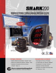
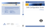
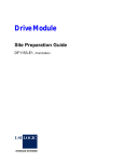
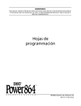
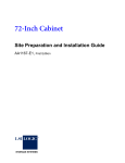
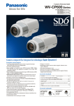
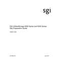
E2600 DSA E-Series iSCSI Disk Arrays
en
Quick Install Guide
E2600 DSA E-Series iSCSI Disk Arrays
Table of Contents | en
3
Table of contents
1
Before you begin
4
1.1
Learn about management methods
4
1.2
What you need for assembly
4
2
Device view
6
3
Install the mounting rails
7
4
Install the controller-drive tray
8
5
Secure the controller-drive tray
9
6
Connect the cables
10
7
Turn on the DC power
13
8
Turn on the AC power
15
9
Install and configure the storage array
16
Bosch Sicherheitssysteme GmbH
Quick Install Guide
07/2012 | V1 |
4
en | Before you begin
1
E2600 DSA E-Series iSCSI Disk Arrays
Before you begin
For warnings and detailed installation instructions, refer to the E2600 DSA E-Series
Installation manual and additional documentation in the Online Product Catalog on http://
www.boschsecurity.com > Video > Digital Recording and Storage > Disk Arrays (Network
Attached) > DSA – Disk Arrays > DSA E-Series iSCSI Disk Arrays. (The navigation path is
subject to change).
Management methods are specific to the installation steps in Section 6 and Section 9.
1.1
Learn about management methods
In-band management
Management using the I/O connections between the host and the storage. The host must still
have Ethernet capabilities.
–
Access volume
Used to communicate management requests and event information. An access volume is
needed for only in-band management.
Out-of-band management
Management directly through the Ethernet connections on each controller using one of the
network configurations from the following list (the command line interface CLI might be
required):
–
DHCP server
Permits nodes to dynamically acquire network addresses.
–
Ethernet IP address
Permits direct connection to controller A or controller B by using an IP address in the
form of xxx.xxx.xxx.yyy and xxx.xxx.xxx.yyz.
–
Static IP address
–
Router advertisements
–
MAC address
Recommended for out-of-band management using IPv4 networks.
Recommended for out-of-band management using IPv6 networks.
Associates the media address control (MAC) address (xx:xx:xx:xx:xx:xx) of each controller
with an assigned IP address.
1.2
What you need for assembly
E2600 controller-drive tray ship group
–
One two-unit (2U) -high E2600 controller-drive tray
–
Two power cords
–
One cabinet mounting hardware kit, including:
–
Two mounting rails (right and left assemblies)
–
Eight M5 x 8 mm screws – Use six screws to secure the mounting rails and two
screws to secure the front of the controller-drive tray to the cabinet.
–
Two M4 x 8 mm screws – Use the screws to secure the rear of the controller-drive
tray to the mounting rails.
Options
–
Drives (two minimum for each controller-drive tray)
–
DC power cords for the optional –48 VDC power option
If you have any questions about the firmware or your configuration, contact your Customer
and Technical Support representative.
Tools
–
07/2012 | V1 |
An Internet connection
Quick Install Guide
Bosch Sicherheitssysteme GmbH
E2600 DSA E-Series iSCSI Disk Arrays
Before you begin | en
–
A cart to hold the controller-drive tray and its components
–
Labels for the cable connections
–
A medium flat-blade screwdriver
–
A No. 2 Phillips screwdriver
–
Anti-static protection
–
A flashlight
Bosch Sicherheitssysteme GmbH
Quick Install Guide
5
07/2012 | V1 |
6
en | Device view
2
E2600 DSA E-Series iSCSI Disk Arrays
Device view
Controller-Drive Tray (12 Drives) – Front View
1 2 3 4
5
6
!
Figure 2.1: Front View E2600
1
Standby Power LED
4
Service Action Required LED
2
Power LED
5
Locate LED
3
Over-Temperature LED
6
Drive Canister
2
Power-Fan Canister
Controller-Drive Tray – Rear View
1
2
Figure 2.2: Rear View E2600
1
07/2012 | V1 |
Controller Canister
Quick Install Guide
Bosch Sicherheitssysteme GmbH
E2600 DSA E-Series iSCSI Disk Arrays
3
Install the mounting rails | en
7
Install the mounting rails
You can install the drive tray into an industry-standard cabinet.
There must be a minimum depth of 76 cm (30 in.) between the front EIA support rails and the
rear EIA support rails.
1.
Position the mounting rails in the cabinet.
–
If you are installing the mounting rails above an existing tray, position the mounting
rails directly above the tray.
–
If you are installing the mounting rails below an existing tray, allow 8.9-cm (3.5-in.)
vertical clearance for the controller-drive tray.
2.
Starting with the left mounting rail, use a flat-blade screwdriver to loosen the two flathead rail adjustment screws. Hold the front of the left mounting rail against the inside of
the front cabinet-mounting flange, and then extend the rear of the mounting rail until it
makes contact with the rear cabinet-mounting flange. The alignment pins at the rear of
the mounting rail should slide into the holes at the rear of the cabinet.
1
2
1
4
3
Figure 3.1: Mounting Rails
3.
1
Mounting Holes on the Industry-Standard Cabinet
2
Adjustment Screws for Locking the Length of the Mounting Rail
3
Mounting Rail
4
Clip for Securing the Rear of the Controller-Drive Tray
From the front of the cabinet, with the mounting-rail flanges inside of the cabinet’s
mounting rail assemblies, use the Phillips screwdriver to loosely tighten only the lower
screw.
4.
From the rear of the cabinet, use the Phillips screwdriver to loosely tighten the two
screws. Do not completely tighten the screws until you have installed the controller-drive
tray in the cabinet.
5.
Repeat step 1 through step 4 for the right mounting rail.
6.
Tighten the fl at-head rail adjustment screws on both mounting rails.
Bosch Sicherheitssysteme GmbH
Quick Install Guide
07/2012 | V1 |
8
en | Install the controller-drive tray
E2600 DSA E-Series iSCSI Disk Arrays
Install the controller-drive tray
4
Warning!
Risk of bodily injury
!
,
Two persons are required to safely lift the component.
1.
With the help of one other person, remove the controller-drive tray from the shipping box.
2.
With the help of one other person, slide the rear of the controller-drive tray onto the
mounting rails so that the mounting holes on the front flanges of the controller-drive tray
align with the mounting holes on the front of the mounting rails.
07/2012 | V1 |
Quick Install Guide
Bosch Sicherheitssysteme GmbH
E2600 DSA E-Series iSCSI Disk Arrays
5
Secure the controller-drive tray | en
9
Secure the controller-drive tray
Warning!
Risk of bodily injury
Do not use equipment in the cabinet as a shelf or work space.
!
1.
Secure the screws in the top mounting holes and the bottom mounting holes on each
side of the controller-drive tray.
2
1
2
1
Figure 5.1: Controller-Drive Tray (12 Drives)
Mounting Holes
1
2.
2
Screws
Secure the rear of the controller-drive tray to the cabinet by using two screws to attach
the flanges on each side at the rear of the controller-drive tray to the mounting rails.
3.
Install the front end caps on the front of the controller-drive tray by pressing the front
end caps into place on the left side and the right side.
Note:
You will install the DE1600 drive trays below and above the controller-drive tray, keeping
the weight in the lower portion of the cabinet. You can install a maximum of 192 drives,
including the 12 drives in the E2600 controller-drive tray. If needed, refer to E2600
Controller-Drive Tray Installation manual.
Bosch Sicherheitssysteme GmbH
Quick Install Guide
07/2012 | V1 |
10
en | Connect the cables
6
E2600 DSA E-Series iSCSI Disk Arrays
Connect the cables
Warning!
!
Risk of exposure to laser radiation
Do not disassemble or remove any part of a Small Form-factor Pluggable (SFP) transceiver
because you might be exposed to laser radiation.
In this step, you will connect the E2600 controller-drive tray to the host or hosts, and then you
will connect the DE1600 drive tray to either a E2600 controller-drive tray (which contains the
controllers), or to another DE1600 drive tray in the storage array.
For more information, refer to these documents:
–
DE1600 Drive Tray Quick Install Guide
–
E2600 Installation manual
You can find the E2600 Controller-Drive Tray Installation manual and additional documentation
in the Online Product Catalog on http://www.boschsecurity.com > Video > Digital Recording
and Storage > Disk Arrays (Network Attached) > DSA – Disk Arrays > DSA E-Series iSCSI Disk
Arrays. (The navigation path is subject to change).
Host-to-Controller Cabling
1.
Attach the appropriate cables and components for the relevant protocol (Fibre Channel,
SAS, or Ethernet).
2.
Choose the host connection configuration (examples follow).
–
Direct topology
Connect the cable from the host port on the controller to either an HBA port, a SAS
port, a host channel adapter (HCA) Fibre Channel port, or an Ethernet adapter
(iSCSI) on the host. The fi gures on the next page all show the HBA port option on
the host.
–
Switch or fabric topology
Connect the cable from the host port on the controller to a port on the switch, and
make sure that the HBA and the controller are in the same zone on the switch.
–
Mixed topology
Use a combination of direct topology and fabric topology.
3.
Repeat step 1 through step 2 for each controller and host channel that you intend to use.
4.
When you are finished, label each end of the cable with information about its connection.
Direct Topology – Two Hosts and a Dual Controller-Drive Tray for Maximum
Redundancy
(For more examples of a switch or fabric topology or of a mixed topology, refer to E2600
Installation manual)
07/2012 | V1 |
Quick Install Guide
Bosch Sicherheitssysteme GmbH
Connect the cables | en
E2600 DSA E-Series iSCSI Disk Arrays
1
1
2
3
2
3
4
5
4
5
6
5.
11
7
Cable the drive trays as needed. For maximum redundancy and tray loss protection, see
the following figure. Refer to Hardware Cabling for detailed information.
Note:
–
The number of drive trays may vary as long as the maximum number of drives is not
exceeded.
–
You can connect a combination of drive trays for a maximum of 192 drives, including
the 12 drives in the E2600 controller-drive tray.
Bosch Sicherheitssysteme GmbH
Quick Install Guide
07/2012 | V1 |
12
en | Connect the cables
E2600 DSA E-Series iSCSI Disk Arrays
Chamonix
A A
Contr
oller
Chamonix
B
Contr
oller
B
Exp
Exp
SAS IN SAS IN
SAS EXP SAS IN SAS IN
SAS EXP
ESM A
ESM B
1A
1B
2A
2B
SAS IN SAS IN
SAS EXP SAS IN SAS IN
SAS EXP
ESM A
ESM B
1A
1B
2A
2B
SAS IN SAS IN
SAS EXP SAS IN SAS IN
SAS EXP
ESM A
ESM B
1A
1B
2A
2B
SAS IN SAS IN
SAS EXP SAS IN SAS IN
SAS EXP
ESM A
ESM B
1A
1B
2A
2B
SAS IN SAS IN
SAS EXP SAS IN SAS IN
SAS EXP
ESM A
ESM B
1A
1B
2A
2B
SAS IN SAS IN
SAS EXP SAS IN SAS IN
SAS EXP
ESM A
ESM B
1A
1B
2A
2B
SAS IN SAS IN
SAS EXP SAS IN SAS IN
SAS EXP
ESM A
ESM B
1A
1B
2A
2B
Steps to connect Ethernet cables for out-of-band management only
1.
Connect one end of the Ethernet cable to the Ethernet port 1 connector on controller A.
2.
Connect the other end of the Ethernet cable to the appropriate Ethernet network
connection or directly to your Ethernet ports on your management station.
3.
07/2012 | V1 |
Repeat step 1 through step 2 for controller B.
Quick Install Guide
Bosch Sicherheitssysteme GmbH
E2600 DSA E-Series iSCSI Disk Arrays
Turn on the DC power | en
13
Turn on the DC power
7
Notice!
i
DC power is an option that is available for use with your E2600 controller-drive tray and drive
trays. If you choose to have –48 VDC power available, you need a qualified service person to
install the equipment that provides special DC power connectors to each power-fan canister
in your storage array.
Warning!
!
Risk of bodily injury
A qualified service person is required to make the DC power connection according to NEC
and CEC guidelines.
Warning!
Risk of electrical shock
!
This unit has more than one power source. To remove all power from the unit, all DC MAINS
must be disconnected by removing all power connectors (item 4 below) from the power supplies.
-
+
1
2
3
4
Figure 7.1: Power cable
1
Supply (Negative), Brown Wire, –
3
Ground, Green/Yellow Wire
4
DC Power Connector
48 VDC
2
Return (Positive), Blue Wire
Warning!
Risk of bodily injury
!
Each tray has more than one power cord. To remove all electrical current from the devices,
make sure that all of the power cords are disconnected from the power source and that the
two-pole 20-amp circuit breaker for the storage array has been disconnected.
Bosch Sicherheitssysteme GmbH
Quick Install Guide
07/2012 | V1 |
14
en | Turn on the DC power
E2600 DSA E-Series iSCSI Disk Arrays
2
1
You must follow the power sequence in the order shown. To establish power redundancy for
trays with two power supplies, use a separate power source for each power-fan canister. For
additional redundancy, you can connect each DC power connector on the same power-fan
canister to a different power source.
Notice!
i
You must turn on the power to all connected drive trays before you turn on the power to the
E2600 controller-drive tray. Performing this action makes sure that the controllers recognize
each attached drive tray.
1.
Disconnect the two-pole 20-amp circuit breaker for the storage array
2.
Make sure that all of the DC Power switches on the DC-powered controller-drive tray and
the DC-powered drive trays are turned off.
3.
Connect the DC power connector cables to the DC power connectors on the rear of the
controller-drive tray and the drive trays.
4.
Have a qualifi ed service person connect the other end of the DC power connector cables
to the DC power plant equipment.
5.
Turn on the Power switch on each power-fan canister in all of the drive trays.
6.
Turn on the Power switch on each power-fan canister in the controller-drive tray.
Note:
When turning off the power to the storage array, perform the procedure in the reverse
order. Turn off the power first to the controller-drive tray, and then turn off the power to
the drive trays.
07/2012 | V1 |
Quick Install Guide
Bosch Sicherheitssysteme GmbH
E2600 DSA E-Series iSCSI Disk Arrays
Turn on the AC power | en
15
Turn on the AC power
8
2
1
You must follow the power sequence in the order shown for turning on AC power to
controller-drive trays and drive trays that use AC power. To establish power redundancy for
trays with two power supplies, use at least two different power distribution units (PDUs) in
the cabinet. Split the power connections from each tray into the separate PDUs. Then connect
the PDUs to external power receptacles that are on different circuits.
Warning!
!
Risk of bodily injury
Each tray has more than one power cord. To remove all electrical current from the devices,
make sure that all of the power cords are disconnected from the power source.
Notice!
i
You must turn on the power to all connected drive trays before you turn on the power to the
E2600 controller-drive tray. Performing this action makes sure that the controllers recognize
each attached drive tray.
1.
Turn off all of the Power switches from the rear of the storage array, and make sure that
all of the power cords are connected.
2.
If the main AC circuit breaker switches in the cabinet are not already turned on, turn on
3.
Turn on the Power switch on each power-fan canister in all of the installed drive trays.
4.
Turn on the Power switches on each power-fan canister in the E2600 controller-drive tray.
the circuit breaker switches.
Note:
When turning off the power to the storage array, perform the procedure in the reverse
order. Turn off the power fi rst to the controller-drive tray, and then turn off the power to
the drive trays.
Bosch Sicherheitssysteme GmbH
Quick Install Guide
07/2012 | V1 |
16
en | Install and configure the storage array
9
E2600 DSA E-Series iSCSI Disk Arrays
Install and configure the storage array
For the basic setup use the VRM Configuration Manager software. For detailed information
refer to the Configuration Manager operating manual.
For advanced features refer to the SANtricity configuration and installation manual.
All necessary documentation can be found in the Online Product Catalog on http://
www.boschsecurity.com > Video > Digital Recording and Storage > Disk Arrays (Network
Attached) > DSA – Disk Arrays > DSA E-Series iSCSI Disk Arrays. (The navigation path is
subject to change).
07/2012 | V1 |
Quick Install Guide
Bosch Sicherheitssysteme GmbH
Bosch Sicherheitssysteme GmbH
Robert-Bosch-Ring 5
85630 Grasbrunn
Germany
www.boschsecurity.com
© Bosch Sicherheitssysteme GmbH, 2012