1
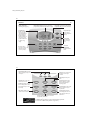
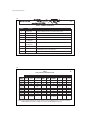
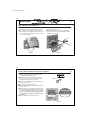
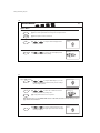
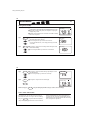
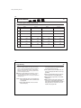
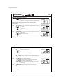
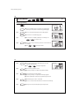
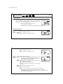
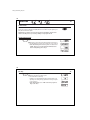
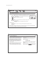
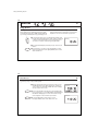
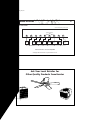
41652_model44760_web.pmd
1
®
Auto Temp Heat Pump Thermostat
Owner’s Manual
Model 44760
41652_model44760_web.pmd
2
Introduction
2
CONGRATULATIONS!
Your new Hunter electronic thermostat will provide years of
reliable service. By saving energy, your thermostat will pay for
itself during its first season of use. Thank you for buying a
Hunter product!
Please read this manual for complete instructions on installing
and operating your thermostat.
If you require further assistance, call Hunter Support at 888830-1326 from 8 AM to 5 PM Central Time.
Model Information:
44760
Model Number ___________________________________________
Serial Number____________________________________________
Date Purchased __________________________________________
Where Purchased _________________________________________
3
Table of Contents
3
INTRODUCTION
Read This Before Installing Thermostat
Features
6
8
INSTALLATION
What You Need
Remove Old Thermostat
Wire Labeling
Mount Wallplate and Thermostat
Connect Wires and Mount Thermostat to Wallplate
10
10
11
14
15
PROGRAMMING
Option Menu
Setting Time and Day
12 Hr. / 24 Hr. Time Format
Programming Introduction
Personal Program Schedule
Programming
Weekday/Weekend Programming
7-Day Programming
Everyday Programming
16
18
19
20
21
23
24
26
28
(continued)
41652_model44760_web.pmd
4
Table of Contents (continued)
4
PROGRAMMING (continued)
Program Options
Programmable Fan
Reviewing Programs
30
30
30
OPERATIONS
Power Switch
System Selection Key
Fan Key
System Indicator Light
Emergency Heat
Reviewing the Current Temperature Setting
Temporary Manual Override
Permanent Manual Override
Vacation (Programmable) Hold
Auto Season Changeover
Home Today
Energy Monitor
Filter Monitor
SPAN Settings
32
32
33
34
35
35
36
37
38
39
40
42
43
44
OPERATIONS (continued)
Auto Recovery
Keyboard Lock
Backlighting (INDIGLO® Night-Light)
45
46
47
SAFETY FEATURES
AC Power Monitor
Low Battery Warning
Error Mode
48
48
49
TROUBLESHOOTING
Problems & Solution
Technical Support
50
51
WIRING DIAGRAM
Heat Pump Systems
52
5
41652_model44760_web.pmd
6
Read This Before Installing Thermostat
IMPORTANT
Read the entire installation section of this Owner’s Manual
thoroughly before you begin to install or operate your
Hunter Thermostat.
6
1
SYSTEM COMPATIBILITY
Your Thermostat is designed to operate these
24-Volt systems:
Remove the Mylar label from the LCD display window.
■ Multi-stage heat pumps with auxiliary heat
■ Single-stage heat pumps
4
INSTALLATION
All installation is normally performed at your
thermostat.
This thermostat will not control 120/240 Volt systems or
millivolt systems.
ARMCHAIR PROGRAMMING
You can program your thermostat before installation by inserting the batteries and following the instructions starting
on page 16. This can be done while you relax in your favorite
chair and is a very good way to familiarize yourself with all the
functions of your Hunter Thermostat.
5
2
3
COMPRESSOR PROTECTION
The thermostat provides a 3.5 minute delay after shutting off
the heating or cooling system before it can be restarted.
This feature will prevent damage to your compressor caused
by rapid cycling.
7
TEMPERATURE RANGE
Your thermostat can be programmed between 45°F and 95°F
(7°C and 35°C). However, it will display room temperatures
from 15°F to 99°F (-9°C and 37°C). “HI” will be displayed if the
temperature is higher than 99°F (37°C), and “LO” will be displayed if the temperature is lower than 15°F (-9°C).
6
AUTO RECOVERY
Your thermostat is set from the factory to gradually recover
the room temperature from an energy saving program to
your comfort program. Therefore, the thermostat may turn your
system on several minutes prior to your programmed time. This
operation is normal, but can be turned off. Refer to the Options
Menu information on pages 16.
7
OPERATION
This system operates on your system’s 24 Volt power supply.
The supply is monitored by the thermostat, and it will stop
functioning if AC power is lost. (When using backup batteries,
“No AC Pwr” will be displayed.) All system controls will remain
off until power is restored.
8
NOTE: The INDIGLO® Night-Light will not function when
AC power is lost.
BATTERY WARNING
Fresh alkaline batteries will provide over one year of memory
backup and clock operation. However, when the batteries
become drained, a low battery warning will appear on the display. When this message occurs, install 2 new AAA batteries. You
have approximately 30 seconds when changing the batteries to
keep thermostat’s clock and program settings.
9
NOTE: The default system selection at power-on is HEAT.
Batteries are recommended to prevent an undesired system change due to a power outage.
41652_model44760_web.pmd
8
Features
®
INDIGLO Night-Light
activated by pressing any key.
8
Alpha-numeric display shows time, day, temperature,
program number, and other feature information as required.
Energy Monitor:
Measures and displays
heating and cooling
system operating time for
Today, Yesterday, This
Month, Last Month, or
Total. By monitoring your
energy usage, you can
program the thermostat
to optimize energy
savings.
Home Today: Overrides energy-saving program
temperatures while you are at home for the day.
Temperature Keys:
Keys for raising or
lowering temperature
settings.
Power Switch:
Select ON, Positive
OFF, or Emergency
Heat.
Soft-touch
programming
keypad, see details
below.
Reset: Press with a
paper clip to reset the
thermostat and return
to power-up settings.
9
System Indicator LEDs: Show status
of Stage 1, Emergency, Stage 2, and
Check System.
Fan Key: Used to select fan mode.
Select Auto, ON, or Program
Controlled.
Option Key: Enters the option
menu.
System Key: Use to select system.
Select Heat, Cool or Auto.
Program Key: Enters Program
Mode for reviewing or chaning
Weekday, Weekend, Daily or
Everyday programs.
Day/Time Key: Used for entering
the Clock setting mode. Use with
the Up and Down keys to set the
time and day.
Program-Day Key: Selects the day
or days to review or change in
Program Mode.
Filter: Displays the filter usage
counter in hours and minutes.
Return-Clear Key: Returns to
normal display mode. Also clears
Filter and Energy counters, and
HOLD modes.
Vacation / Hold: Enters permanent and vacation
(Programmable) HOLD modes.
As an ENERGY STAR® Partner, Hunter Fan Company has determined that this programmable
thermostat meets the ENERGY STAR® guidelines for energy efficiency.
41652_model44760_web.pmd
10
INSTALLATION
10
What You Need
This thermostat includes two #8 slotted screws and two wall anchors for mounting. To install your thermostat, you should have
the following tools and materials.
■ Slotted Screwdriver(s)
■ Phillips Screwdriver
■ Hammer
■ Electric drill and 3/16" bit
■ Two 1.5 V (AA) size alkaline batteries
Remove Old Thermostat
CAUTION: Do not remove any wiring from existing thermostat before reading the instructions carefully. WIRES
MUST BE LABELED PRIOR TO REMOVAL.
■ IMPORTANT! Turn off the power to the furnace at the main
power panel or at the furnace.
■ Remove existing thermostat cover. See Figure 1. Some thermostats will have screws or other locking devices that must
first be removed. Once wall mounting plate is exposed, look
for wires.
If wires are not visible, they may be connected to the back of
the wallplate. Again, look for screws, tabs, etc. Some models
have doors that open to expose wires and mounting screws.
(See Figure 1).
TYPICAL HOME THERMOSTATS
Figure 1
Wall Mounting Plate
Thermostat
Cover
Wall Mounting Plate
Thermostat
Cover
11
Wire Labeling
■ Each wire coming from the wall to the existing thermostat is
connected to a terminal point on that thermostat. Each of
these terminal points is usually marked with a code letter as
shown in Table A on the next page.
■ The number of wires in your system can be as few as four
(for single-stage systems), as many as eight, or any number
in between. If you follow the labeling procedures correctly,
you do not have to be concerned about how many wires
there are.
■ IMPORTANT! BEFORE DISCONNECTING ANY WIRES, APPLY
THE SELF-ADHESIVE LABELS PROVIDED TO THE WIRE AS
11
SHOWN IN TABLE A and B ON PAGES 12-13. (For example,
attach the label marked W to the wire that goes to the W or H
terminal on your existing thermostat.) IGNORE THE COLOR OF
THE WIRES since these do not always comply with the standard.
■ After labeling wires, disconnect them from the existing thermostat terminals.
■ Remove existing wallplate. To make sure wires do not fall back
into wall opening, you may want to tape them to the wall.
■ If hole in wall is larger than necessary for wires, seal this hole
so that no hot or cold air can enter the back of the thermostat
from the wall. This air could cause a false thermostat reading.
(continued)
41652_model44760_web.pmd
12
INSTALLATION
12
TABLE A – TERMINAL DESCRIPTIONS
TERMINAL
LABELS
FUNCTION
(HEAT PUMP)
COMMENTS
R
24V AC supply
Hot wire of 24VAC transformer. Powers the thermostat & system.
Y1
Compressor stage 1
Activates the 1st stage compressor. (Heat or Cool for Heat Pumps)
W2
Auxiliary heating
Activates the 2nd stage (auxiliary) heating when required.
E
Emergency heating
Activates Emergency heating ONLY when the System Switch is in Emergency (em) Mode.
O
Reversing valve
(cooling mode)
Activates reversing valve in COOL mode. ALWAYS ON in COOL MODE.
B
Reversing valve
(heating mode)
Activates reversing valve in HEAT mode. ALWAYS ON in HEAT MODE.
G
Fan
Activates the system Fan. (Can be Auto, On, or Program controlled)
L
System monitor
Activates System Check LED on the front of thermostat.
(Controlled by the system, not the thermostat.)
C
24V AC common
Common wire of 24V AC transformer. REQUIRED for thermostat operation.
13
13
TABLE B
HEAT PUMP CROSS-REFERENCE CHART
EXAMPLES OF DIFFERENT SYSTEM TERMINALS
HUNTER
TERMINALS
CARRIER
COLEMAN
COMFORTMAKER
BRYANT,
PAYNE
RHEEMRUUD
TRANE,
WEATHERTRON
YORK
LENNOX (1)
LENNOX (2)
R
R
R
R
R
R
R
R
R
V-VR
Y1
Y or Y1
Y
Y
Y
Y
Y
Y
Y
M
W2
W2
W2
W1
W2
W2
W
W
W1
Y
E
E
E
jumper
to W2
E
E
X2
jumper
to W2
E
E
O
O
O
O
O
O
O
R
G
G
G
F
X
L
B
C
B
B
B
G
G
G
G
G
G
L
L or F
L
L or X
L
L
C
C
X
C, X, X1
C, C1, X1
X
Note: W2 wires
no connection
B
X
Note: T wire
no connection
NOTE: If your heat pump thermostat does not have an E wire, use the provided jumper wire to connect the E terminal to
the W2 terminal, as shown in three examples above. Refer to the Wiring Diagram on page 52.
41652_model44760_web.pmd
14
INSTALLATION
14
Mount Wallplate and Thermostat
■ Remove the wallplate from your thermostat by pressing the
release tab on the bottom of the thermostat. (See Figure 2.)
■ Position wallplate on wall and pull existing wires through
large opening. Then level for appearance. Mark holes for plastic anchors provided if your existing holes do not line up with
those on the Hunter wallplate.
■ Drill holes with 3/16" bit and gently tap anchors into the
holes until flush with wall.
■ Reposition wallplate to wall, pulling wires through large
opening. Insert mounting screws provided into wall anchor
and tighten. (See Figure 3.)
C
O
F
Y1
W2
G
R
Figure 2
Figure 3
15
Connect Wires and Mount Thermostat to Wallplate
■ Straighten bare end of each wire and cut or strip it to 1/4”
maximum. Insert each labeled wire into the bottom of the
maching terminal. Refer to figures 4 and 5.
■ Hold the wires in each terminal and tighten the terminal
screws securely, otherwise a loose wire could cause operational problems with your system or thermostat.
■ Push excess wire back into hole to prevent interference with
mounting of the thermostat.
■ Make sure the Power Switch is set to OFF.
■ Insert two AAA size alkaline batteries, observing the polarity
marked on the unit.
■ Insert the upper tabs on the thermostat body into the slot at
the top of the wallplate. Press bottom of the thermostat body
to snap it into the wallplate. (NOTE: Do not force the thermostat onto the wallplate, as the terminal pins may be
damaged. If it does not snap properly, the thermostat
may not work.)
■ Switch on the main power at the panel or furnace.
15
R
Figure 4
R
Y1
Insert
G C L O W2 B E R Y1
G C L O W2 B E R Y1
Figure 5
41652_model44760_web.pmd
16
PROGRAMMING
16
Option Menu
Your thermostat has many settings that can be adjusted to fit your system and preferences.
■ Press to enter the Option Menu and to change to the next option selection.
option
■ Press at any time to return to normal mode.
ret-clear
Fahrenheit or Celsius (F°/C°) selection
option
1
■
or
to change the thermostat display between
Te m p
to change the time format display between
Clock
Fahrenheit and Celsius.
12 Hr or 24 Hr. Clock selection
option
2
■
or
12 hour (AM / PM) and 24 hour (military).
17
Stage 1 SPAN selection
option
3
■
or
to change the SPAN setting to 1, 2, or 3. The
Span Stg1
factory setting is 2. Setting 1 will cause shorter cycle times. Setting 3
will cause longer cycle times.
Auto Recovery selection
option
4
system
■
or
to enable “YES” or disable “NO” the Auto
Recovery Mode. The factory setting is “YES.”
■ To change between Heat or Cool recovery modes.
Recovery
System
NOTE: Auto Recovery is one of the ENERGY STAR® features of this thermostat. Refer to the Auto Recovery section on
pages 45-46 for more information.
LCD Contrast adjustment
■
option
5
or
to change the LCD contrast between 0 and 9.
Lower numbers lighten the display. Higher numbers darken the display.
The factory setting is 5.
LC D
41652_model44760_web.pmd
18
PROGRAMMING
18
Setting Time and Day
■ The LCD will show this information when batteries are first installed, or after
the Reset button is pressed. The temperature will update after a few seconds.
■ During time and day setting mode, the temperature and program
displays will go blank.
Monday
4
Temp
AM
System
Fan
■ Example: Set the Thermostat to the current time of 2:16 PM on Saturday.
Refer to the Steps below.
Step 1
day-time
■ Press to enter time and day setting mode. The current hour and the
AM / PM indicator will be flashing.
■ Press to change the Hour up or down to the current hour.
or
Step 2
day-time
Monday
AM
Note the AM / PM indicator, as the display will change at 12 AM
and 12 PM.
■ Press again to change from hour setting to minute setting. The current
minute will be flashing.
■ Press to change the Minute up or down to the current minute.
or
Monday
PM
19
Step 3
day-time
■ Press again to change from minute setting to day setting. The current
day will be flashing.
Saturday
■ Press to change the Day up or down to the current day.
PM
or
Step 4
day-time
or
■ Press again to change back to the normal display.
Saturday
2
Temp
AM
ret-clear
System
Fan
NOTE: You may press ret-clear at any time during Day and Time setting to return to the normal display.
12 Hr. / 24 Hr. Time Format
Your thermostat is set from the factory in normal 12
(AM / PM) time format. To change to 24 hour (military)
time, press
option
at any time while the Hour, Minute,
or Day is flashing to toggle between the 12 hour and 24 hour
formats. The AM / PM indicator will not be displayed in 24
hour mode. Both the current time and all programs will automatically change to the selected format. The time format may
also be changed in the Option Menu.
41652_model44760_web.pmd
22
PROGRAMMING
22
Personal Program Schedule (continued)
Cooling
Day
Prog. 1
Prog. 2
Prog. 3
Prog. 4
Mon.
Time
Temp
Time
Temp
Time
Temp
Time
Temp
Tues.
Time
Temp
Time
Temp
Time
Temp
Time
Temp
Wed.
Time
Temp
Time
Temp
Time
Temp
Time
Temp
Thurs.
Time
Temp
Time
Temp
Time
Temp
Time
Temp
Fri.
Time
Temp
Time
Temp
Time
Temp
Time
Temp
Sat.
Time
Temp
Time
Temp
Time
Temp
Time
Temp
Sun.
Time
Temp
Time
Temp
Time
Temp
Time
Temp
23
Programming
■ Your thermostat can be programmed for weekdays and weekends, have unique programs for all 7 days, or the same program for everyday. Use Weekday/Weekend Programming on
page 24, 7-day Programming on page 26, or Everyday Programming on page 28 to enter or revise programs to match
your Personal Program Schedule.
■ Familiarize yourself with Manual Programming, so that you
can easily modify your programs as your comfort needs
change. Follow the steps below to change the program times
and temperatures.
NOTE: 1) The program time can be set in 10 minute increments, and remains the same for both Heat and
Cool programs.
2) The program temperature can be set in increments of 1°F (1°C).
23
3) The Heat setpoint can not be set higher than the
Cool setpoint, and the Cool setpoint can not be
set lower than the Heat setpoint.
4) If the system selector is in AUTO mode, the
current operating mode will be used for programming.
5) After 15 seconds without a key press, the thermostat will return to normal display mode.
6) When setting the program time, note the AM /
PM indicator.
7) With the Auto Recovery feature enabled, you do
not need to set your comfort program times
early. Auto Recovery will determine how early to
turn your system on, so that the room is comfortable at the program time.
41652_model44760_web.pmd
24
PROGRAMMING
24
Weekday/Weekend Programming
■ Slide Power Switch to ON.
Step 1
on off em
■ Press to select HEAT or COOL to program the corresponding system.
(AUTO may be selected, but does not affect the programming steps.)
NOTE: If the power switch is in the OFF position, the last system selected will
be programmed.
Step 2
program
Step 3
or
Step 4
program
■ Press to enter program mode. Weekdays are displayed and program
1 is flashing.
■ The Program hour and AM or PM indicator are flashing. Press to
change the hour.
■ Press again to change to the minute position. The current minute
will be flashing.
■ Press to change the minute.
Thursday
2
Temp
AM
System
Fan
Weekdays
1 2 3 4
Temp
AM
System
Fan
Weekdays
1 2 3 4
Temp
AM
or
System
Fan
25
Step 5
program
■ Press again to change to the program temperature. The current
temperature will be flashing.
■ Press to change the temperature.
or
Step 6
program
Weekdays
1 2 3 4
Temp
AM
System
Fan
■ Press again to move to the next program number.
■ Repeat Steps 3 through 5 to change the remaining Weekday programs.
Step 7
prog-day
■ Press to change to Weekend programs.
■ Repeat steps 3 through 5 to complete the weekend programs.
ret-clear
■ Press at any time to exit the Program Mode.
■ After 15 seconds, the thermostat will return to normal mode
automatically.
Step 8
system
■ Change to the other system, and repeat steps 2 through 7.
Weekends
1 2 3 4
Temp
AM
System
Fan
41652_model44760_web.pmd
26
PROGRAMMING
26
7-Day Programming
■ Slide Power Switch to ON.
Step 1
Thursday
on off em
Step 2
2
Temp
AM
system
■ Press to select HEAT or COOL to program the corresponding system.
(Auto may be selected, but does not affect the programming steps)
program
■ Press to enter program mode, display shows weekday programs.
prog-day
■ Press 2 times to reach the Monday program.
System
Fan
Monday
1 2 3 4
Temp
AM
System
Fan
■ The Program hour and AM or PM indicator are flashing. Press
Step 3
or
to change the hour.
Monday
Step 4
program
■ Press again to change to the minute position. The current minute will
be flashing.
or
Temp
AM
System
■ Press
1 2 3 4
Fan
to change the minute.
27
Step 5
program
■ Press again to change to the program temperature. The current
temperature will be flashing.
■ Press
or
to change the temperature.
Monday
program
■ Press to move to programs 2, 3 and 4.
■ Repeat Steps 3 through 5 to complete the programs for Monday.
Step 7
prog-day
■ Press to change to the next day’s programs.
■ Repeat Steps 3 through 6 to complete the selected day’s programs.
■ Continue repeating Steps 3 through 7 to program all 7 days of the week.
Step 8
ret-clear
■ When finished, press to return to normal mode.
■ After 15 seconds, the thermostat will return to normal mode automatically.
Step 9
system
■ Change to the other system and repeat steps 2 through 8 above.
Temp
AM
System
Step 6
1 2 3 4
Fan
41652_model44760_web.pmd
28
PROGRAMMING
28
Everyday Programming
■ Slide Power Switch to ON.
Step 1
on off em
Step 2
Thursday
■ Press to select HEAT or COOL to program the corresponding system.
(Auto may be selected, but does not affect the programming steps)
program
■ Press to enter program mode, display shows weekday programs.
prog-day
■ Press 9 times to reach the Everyday program.
System
Fan
Everyday
1 2 3 4
Temp
AM
System
or
Temp
AM
system
Step 3
2
Fan
■ The Program hour and AM or PM indicator are flashing. Press to
change the hour.
29
Step 4
program
■ Press again to change the minute position. The current minute will
be flashing.
Everyday
■ Press to change the minute.
AM
or
Step 5
program
or
Step 6
program
System
■ Press again to change to the program temperature. The current temperature will be flashing.
■ Press to change the temperature.
■ Repeat Steps 3 through 5 to change the remaining programs.
ret-clear
■ Press at any time to exit the Program Mode.
■ After 15 seconds, the thermostat will return to Normal
mode automatically.
Step 7
system
■ Change to the other system and repeat steps 2 through 6.
Temp
Fan
Everyday
1 2 3 4
Temp
AM
System
■ Press again to move the next program number.
1 2 3 4
Fan
41652_model44760_web.pmd
30
PROGRAMMING
30
Program Options
Programmable Fan
fan
■ Any time during programming, this will change the fan display between
“AUTO” and “ON” for the selected system and Program number. (Heat
and Cool can be set separately.)
“AUTO” = Fan control runs when the system is ON
“ON” = Fan control runs continuously
Weekdays
1 2 3 4
Temp
AM
System
Fan
NOTE: Fan must be set to “PGM” for the Programmable Fan to be activated.
Reviewing Programs
You may want to review the programs to confirm that the settings are compatible with your lifestyle.
Weekday
Programs
program
■ Press to display M - F programs.
■ Press repeatedly to cycle through the 4 programs.
Weekdays
1 2 3 4
Temp
AM
System
Fan
31
■ Press to display the Sa - Su programs.
■ Press repeatedly to cycle through the 4 programs.
Weekends
System
Daily and
Everyday
Programs
program
prog-day
■ Press to display M - F programs.
NOTE: Time or Temperature display will be blank when at least
one weekday program is different. (All programs will de displayed if programmed in Everyday mode.)
Temp
AM
Fan
Weekdays
System
1 2 3 4
Temp
Fan
■ Press to change to Sa - Su. Again, if part of the display is blank, one of
the weekend programs is different.
■ Press again to change to Monday’s program.
■ Continue pressing to cycle through each day, or to reach the Everyday
programs.
program
■ Press repeatedly to cycle through the 4 programs.
■ Press to return to normal mode.
■ After 15 seconds, the thermostat will return to normal mode automatically.
NOTE: Programs take affect as soon as the thermostat returns to normal mode.
If you are armchair programming the thermostat, slide the system selector to the OFF position before
mounting the thermostat to the wallplate.
41652_model44760_web.pmd
32
OPERATION
32
Power Switch
The Power switch on the front of the thermostat determines the operating mode of the thermostat.
You may select ON, OFF or Emergency Heat (EM). When the Power Switch is OFF, all outputs are positively disconnected from the system.
on off em
NOTE: Anytime you install or remove the thermostat from the wallplate, slide the Power
Switch to the OFF position to prevent the possibility of a rapid system On-Off.
System Selection Key
system
■ Press to select the desired system.
System
■ When Auto is selected, the system will change between Heat and Cool
automatically. Refer to the Auto Season Changeover section on page 39.
System
NOTE: The default system selection at power-on or after a reset
is HEAT. Therefore it is recommended that 2 AAA batteries be
used for backup during power outages.
System
System
33
Fan Key
33
fan
■ Press to set the fan operation.
Fan
■ AUTO: the fan will turn on with the system.
ON: the fan will run continuously.
PGM Auto or ON: (Programmable Fan) The fan will select AUTO or ON,
depending on the setting in the programs. Refer to the Program Option
section on page 30.
NOTE: The fan must be set to “PGM” for the fan’s program settings to take effect.
Fan
Fan
Fan
41652_model44760_web.pmd
38
OPERATION
38
Vacation (Programmable) Hold
This thermostat can hold a fixed temperature for a selected number of days (up to 30). After the selected number of days, the thermostat will return to normal program operation. This feature allows you to return home to your normal comfort setpoint temperatures.
vacation
hold
■ Press and hold for 2 seconds to enter Vacation Hold mode. The set temperature will be the current room temperature and the Vacation counter
will be set to 1 day.
■ Use to set the Vacation Hold temperature.
or
day-time
Vacation
Day
System
Set Temp
Temp
Fan
■ Press to set the Vacation Hold counter to the number of days you will be
away from home.
■ “Vacation” will alternate on the display with the day and any other
messages.
To end Vacation Hold:
ret-clear
■ Press to return to the current program. The flashing Vacation display will be canceled.
NOTE: The Auto Season Changeover feature will not operate while the thermostat is in Vacation (Programmable) HOLD.
Refer to the Auto Season changeover feature on page 39 for more information.
39
Auto Season Changeover
When the System Selection is in AUTO position, the thermostat
will automatically change between Heating and Cooling systems,
depending on your program. We recommend keeping your programmed heating and cooling temperatures at least 5°F (3°C)
apart to allow the Auto Season Changeover to occur when the
appropriate temperature span has been reached. However, if
your heating and cooling programs set temperatures are close,
there is a built-in program to prevent the thermostat from
changing unnecessarily.
Auto Season Changeover is disabled when the thermostat is in
Temporary or Permanent Override, or Vacation Hold, as these
overrides are energy saving settings. While in any of these
modes, “AUTO” will be temporarily removed form the LCD dis-
39
play. “AUTO” will return when these holds are cleared. Auto Season Changeover will still function in Home Today mode, as this is
a comfort setting.
For example, you may have the following temperatures programmed at a given time:
Heat Set Temp = 68°F
Cool Set Temp = 78°F
If the room temperature rises above 78°F, then the thermostat
will automatically change to cool mode and turn on the air
conditioner.
Likewise, the thermostat will automatically change to heat mode
and turn on heat when the room temperature falls below 68°F.
41652_model44760_web.pmd
40
OPERATION
40
Home Today
This Hunter patented feature allows you to quickly and temporarily override your energy saving program setting on days when you are
normally away from home with one key press.
ho
me today
■ Press to enter the Home Today override. The highest program temperature for today will be selected from your programs in Heat mode and
become the set temperature. (In Cool mode, Home Today will select the
lowest program temperature for today to be the set temperature.)
Home
Temp
PM
System
Fan
■ “HOME” will alternate on the display with the day and any other
messages.
■ When pressed during the first or second program of the day, Home Today will automatically return to program control at the start of the
fourth program of the day. If Home Today is pressed after the start of the
third program time of the day, the thermostat will remain in Home Today mode until the first program of the next day.
ho
me today
■ If Home Today is already active, you may similarly extend it to the first
program of the next day by pressing the key again after the start time of
the third program.
(continued)
41
■ If the system is changed between Heat and Cool modes (either manually
or by Auto Season Changeover) during the “Home Today” override period, the setpoint temperature will be automatically updated. It will automatically change from the highest heat program setpoint to the lowest cool program setpoint, or from the lowest cool program setpoint to
the highest heat program setpoint.
vacation
hold
■ Press to exit Home Today mode before the schedule ending time.
“HOME” is no longer displayed on the LCD screen, and the thermostat
returns to the current program.
■ You can manually change the setpoint temperature while in Home Today
mode. Refer to the Temporary Manual Override instructions on page 36.
Manually changing the set temperature while in Home Today mode will
not affect the Home Today ending time. However, the set temperature
will not change automatically with a manual or Automatic change between heating and cooling.
ho
me today
■ You may also press the Home Today key while in Temporary Manual
Override. The operation is the same as the previous point above.
41652_model44760_web.pmd
42
OPERATION
42
Energy Monitor
r
ne
r g y m o n i to
The Energy monitor feature measures and stores the amount of
time the heating and air conditioning system operates. Usage
can be displayed for Today (since 12AM), Yesterday, This Month
(up to 30 days), Last Month (last 30 days), and Total (up to 999
Hrs. 59 Min.). By monitoring your energy usage, you see how
much the setback periods are saving and you can test program
adjustment to save even more. Use tables on pages 21-22.
■ To review energy usage, press to cycle through Today, Yesterday, [number] Days, Last 30 days, and Total. Press again to return to normal mode,
or wait 15 seconds for the display to return to normal mode. You can
also return to normal mode at any time by pressing RET CLEAR.
Today
Hr
Min
e
■ For example: This LCD display shows Today’s usage to be 10 Hours, 26
minutes.
ret-clear
■ Press and hold for 3 seconds to reset the Energy Monitor’s counters
while in Energy Monitor mode. The display will blink, and all counters
will be cleared to zero.
43
Filter Monitor
43
Your thermostat also keeps a record of the number of hours your filter has been in use. To maximize your system’s performance and energy efficiency, change or clean your filter regularly.
■ When the total system run time for heat and cool reaches 500 hours,
“FILTER” will alternate on the display with the day to remind you to
clean or change your system’s filter. “FILTER” will continue to display
until the counter is set back to zero.
Filter
PM
System
filter
Fan
■ Press to review total filter usage. After 15 seconds, the display will return to normal mode, or you can hit RET CLEAR to exit immediately. The
Filter Monitor will display up to 999 hours and 59 minutes of usage.
In this example, the counter is at 410 Hours, 26 minutes.
ret-clear
4
Temp
■ To reset the Filter Monitor counter, hold for 3 seconds.
The display will blink, and the counter will be reset to zero.
Filter
Hr
Min
41652_model44760_web.pmd
44
OPERATION
44
SPAN Settings
STAGE 1
Your thermostat is set at the factory to cycle at 1°F (0.5°C)
above and below the set temperature in Stage 1. (Span = 2.) This
setting has been designed to provide a comfortable room temperature under most all conditions. However, if you find your system cycling too fast or too slow, then the Span can be adjusted
to modify the cycle time. Refer to the Option Menu Stage 1 Span
selection on page 17.
The Span settings remain the same for both HEAT and COOL.
The Span can be changed at any time and is independent of program times or temperatures.
When the thermostat is powered on or the Reset key is pressed,
the Span is reset back to setting 2.
Span = 1. This decreases the cycle time by causing your
system to run shorter.
Span = 3. This increases the cycle time by causing your
system to run longer.
45
Auto Recovery
45
Hunter’s Auto Recovery feature meets the ENERGY STAR® guidelines for energy efficiency by allowing the heating or cooling system to recover gradually from an energy-saving setpoint temperature to a comfort setpoint temperature.
Auto Recovery calculates how early to turn your system back On,
so that the room temperature is already comfortable by the start
of the comfort temperature program period. Auto Recovery
works in both Heat and Cool modes.
For example, in Heat mode, you could have the following
programs:
Program #4 (Overnight)
Set Temp = 60°F
Time = 10PM
Program #1 (Morning)
Set Temp = 68°F
Time = 6AM
The room temperature fell to 60°F overnight. Rather than having
the thermostat turning on at 6AM, Auto Recovery would note
the temperature difference between 60°F and 68°F and turn the
Heat on approximately 30 minutes early. Therefore, the room
temperature at 6AM would be about 68°F instead of 60°F.
■ When the thermostat is
in Auto Recovery mode,
the display will alternate
“RECOVERY” with the
day, and the program
indicator will flash.
Recovery
2
Temp
PM
System
Fan
Details of Auto Recovery Operation:
■ Auto Recovery can be disabled by selecting “NO” in the Option Menu. Refer to page 17.
■ Auto Recovery will not operate if Permanent hold, Vacation
hold Temporary hold or Home Today is in operation. It will
also not operate if the thermostat resets due to AC power loss
with no backup batteries.
■ Auto Recovery can be canceled manually if RET CLEAR is
pressed during the recovery process. If a recovery process is
canceled manually then the recovery process will not start
again until the next program period starts (an exception is
that if time or program is changed then the thermostat will
check Auto Recovery conditions immediately).
41652_model44760_web.pmd
46
OPERATION
46
Auto Recovery (continued)
■ Auto Recovery will be canceled if HOME TODAY or HOLD is
pressed during the recovery process. The thermostat will enter
Home Today, Permanent hold or Vacation hold.
■ Auto Recovery will be canceled and change to Temporary
Manual Override mode if the setpoint is adjusted during the
recovery process.
■ If the system changes between heat and cool (automatically
or manually) then the thermostat will recalculate Auto Recovery again. Setpoint temperature will be changed to the opposite system’s comfort temperature if the recovery entry criteria
are still met. Otherwise, the recovery process will be canceled
and return to program control mode.
Keyboard Lock
The Keyboard can be locked to prevent unauthorized changes to the thermostat.
and
■ To lock or unlock the keyboard, press and hold BOTH keys for 3 seconds.
The keyboard is locked when KEY LOCK appears on the display.
Key Lock
1
Temp
AM
System
Fan
■ All keys are locked, but any time a key is pressed, KEY LOCK will appear
on the display for 1 second and the backlight will operate.
47
Backlighting (INDIGLO® Night-Light)
47
Your thermostat has an electroluminescent lamp that backlights
the display for easy viewing in the dark.
erate several keys. The backlight will decrease in brightness before shutting off.
When any key is pressed the display is illuminated.
NOTE: The backlight is powered by the 24V AC supply. It
will not operate when there is an AC power interruption
or if the thermostat is removed from the wallplate.
The display will remain illuminated for 15 seconds after the last
key is pressed. This allows the light to stay on if you need to op-
48
SAFETY FEATURES
48
AC Power Monitor
■ This thermostat operates on 24V AC, which is provided by your system’s transformer. If
the system loses electricity, then the 24V AC power is lost also.
■ The 2 AAA batteries provide backup operation of the clock, as well as all programs
and settings.
■ If the AC power is lost, then the LCD display will alternate “No AC Pwr” with the day.
■ Without AC power, the following functions are disabled:
- The system is turned off.
- The Backlight function is disabled.
- The remote sensor temperature readings are not available.
No AC Pwr
3
Temp
PM
System
Fan
Low Batt
Temp
PM
System
Fan
41652_model44760_web.pmd
50
TROUBLESHOOTING
50
Problem
Solution
SCRAMBLED OR DOUBLE DISPLAY
(numbers over numbers)
1. Remove clear Mylar sticker
NO DISPLAY
1. Check terminal connection. A common (C) wire is required for operation.
2. Check battery connections and batteries.
3. Press RESET button with a small pin and hold in for two seconds.
ENTIRE DISPLAY DIMS
1. Replace Batteries
2. Adjust LCD contrast in the Option Menu.
PROGRAM DOES NOT CHANGE
AT YOUR DESIRED SETTING
1.
2.
3.
4.
AUTO / FAN DOES NOT TURN ON
1. Move HG/HE selector to opposite position
FAN RUNS CONTINUOUSLY
1. Check fan setting. It may be “ON” or in Programmable Fan mode “PGMON”.
Problem (cont.)
Solution (cont.)
HEATING OR COOLING DOES
NOT GO ON OR OFF
1. Check that the system selector key is in the correct position (“HEAT,” “COOL”
or “AUTO”).
2. The thermostat may be in the AUTO mode. Look for “AUTO” on the LCD display.
If the Heat and Cool program temperatures are close, then the thermostat requires a larger room temperature change before changing from Heat or Cool.
3. There may be as much as a 4 minute delay before the Heat or Cool system turns
On - wait and check. (Compressor protection delay.)
4. Check your circuit breakers and switches to ensure there is power to the system.
5. Replace batteries.
6. Make sure your furnace blower door is closed properly.
7. Check the position of the Heat Pump or Multi-Stage selector switch.
ERRATIC DISPLAY
1. Press the RESET button once with a small pin and hold for two seconds.
The thermostat will need to be re-programmed.
IF UNIT CONTINUES TO OPERATE
IN THE OFF POSITION
1. Replace unit.
THERMOSTAT PERMANENTLY
READS “HI,” “LO,” OR “Error”
AFTER PRESSING RESET BUTTON
1. Replace unit.
Check that the time is set properly to “AM” or “PM”.
Check that the thermostat is not in “HOLD” or “Home Today” modes.
Check for the correct day setting.
Check any remote sensor readings or weights.
51
If you experience any other problems, call 888-830-1326 from 8 AM to 5 PM Central Time for technical assistance.
51
41652_model44760_web.pmd
52
WIRING DIAGRAMS
52
HEAT PUMP SYSTEMS
Some terminals may not be used
THERMOSTAT WALLPLATE TERMINALS
Optional Jumper*
G
Fan
Relay
C
L
System
Monitor
O
Reversing
Valve Cool
W2
Auxiliary
Heat
B
Reversing
Valve Heat
E
Emergency
Heat
R
24V
Supply
Y1
Compressor
Stage 1
Common
NOTE: Common wire connection is REQUIRED.
*Add jumper between W2 and E on systems without an E wire.
53
Ask Your Local Retailer for
Other Quality Products from Hunter
41652_model44760_web.pmd
56
®
© 2004, Hunter Fan Company Form No. 41652-01, 1/04
Hunter Fan Company
2500 FRISCO AVENUE
MEMPHIS, TN 38114