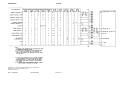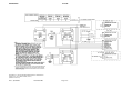
1
INSTALLATION MANUAL
KLN 90B
GPS RNAV
MANUAL NUMBER 006-10521-0005
REVISION 5 April, 2003
WARNING
Prior to Export of this Document, review for export license requirement is needed.
COPYRIGHT NOTICE
©1997,2003 Honeywell International Inc.
Reproduction of this publication or any portion thereof by any means without the express written
permission of Honeywell is prohibited. For further information contact the Manager, Technical
Publications, Honeywell, One Technology Center, 23500 West 105th Street Olathe KS 66061
Telephone: (913) 782-0400.
BENDIX/KING
KLN 90B
SECTION I
GENERAL INFORMATION
Paragraph
Page
1.1
INTRODUCTION...........................................................................................1-1
1.2
EQUIPMENT DESCRIPTION ......................................................................1-1
1.3
TECHNICAL CHARACTERISTICS ..............................................................1-1
1.3.1
ARINC 429 GAMA FORMAT INFORMATION .............................................1-1
1.3.3
UNIT TECHNICAL CHARACTERISTICS .....................................................1-5
1.4
UNITS AND ACCESSORIES SUPPLIED ....................................................1-10
1.4.1
KLN 90B GPS RECEIVER ...........................................................................1-10
1.4.2
GPS ANTENNA ............................................................................................1-11
1.4.3
KLN 90/90B INSTALLATION KITS ..............................................................1-11
1.4.4
KA 91/92 INSTALLATION KIT .....................................................................1-12
1.4.5
DATABASE ..................................................................................................1-12
1.5
ACCESSORIES REQUIRED, BUT NOT SUPPLIED ...................................1-13
1.6
OPTIONAL ACCESSORIES ........................................................................1-13
1.7
LICENSE REQUIREMENTS ........................................................................1-19
1.8
RECOMMENDATIONS FOR IFR APPROVAL ............................................1-19
1.9
INSTRUCTIONS FOR CONTINUED AIR WORTHINESS ............................1-21
Rev 5, April/2003
10521I05.TDC
Page i
BENDIX/KING
KLN 90B
SECTION II
INSTALLATION
ParagraphPage
2.1
GENERAL INFORMATION .......................................................................... 2-1
2.2
UNPACKING AND INSPECTING EQUIPMENT .......................................... 2-1
2.3
EQUIPMENT INSTALLATION...................................................................... 2-1
2.3.1
AVIONICS COOLING REQUIREMENTS
FOR PANEL MOUNTED EQUIPMENT........................................................ 2-1
2.3.2
KLN 90B MECHANICAL INSTALLATION .................................................... 2-1
2.3.3
ANTENNA SELECTION ............................................................................... 2-2
2.3.4
ANTENNA INSTALLATION CONSIDERATIONS......................................... 2-2
2.3.5
ANTENNA MECHANICAL INSTALLATION ................................................. 2-3
2.3.5.1 General ......................................................................................................... 2-3
2.3.5.2 Installation Procedure ................................................................................... 2-3
2.3.6
ELECTRICAL INSTALLATION ..................................................................... 2-3
2.3.6.1 General Information ...................................................................................... 2-3
2.3.6.2 Functional Pinout Descriptions ..................................................................... 2-4
2.4
POST INSTALLATION CHECK OUT INFORMATION ................................. 2-65
2.4.1
KLN 90B RESOLVER CALIBRATION METHOD ......................................... 2-65
2.4.2
POST INSTALLATION CHECKOUT PROCEDURE .................................... 2-65
2.4.3
INSTALLATION CHECK OUT ...................................................................... 2-66
2.4.4
INTEGRATED INSTALLATION CHECK OUT.............................................. 2-67
2.4.4.1 All Installations.............................................................................................. 2-67
2.4.4.2 EFIS or CDI/HSI Interface ............................................................................ 2-67
2.4.4.3 Radar Graphics Interface.............................................................................. 2-68
2.4.4.4 Air Data Interface.......................................................................................... 2-68
2.4.4.5 Gray Code Altitude Inputs............................................................................. 2-68
2.4.4.6 RMI Interface ................................................................................................ 2-68
2.4.4.7 ELT Interface ................................................................................................ 2-68
2.4.4.8 Moving Map Interface ................................................................................... 2-68
2.4.4.9 External Annunciators................................................................................... 2-69
2.4.4.10 Distance Indicator ......................................................................................... 2-69
2.4.4.11 Dataloader .................................................................................................... 2-69
2.4.4.12 ALT ALERT, ALT ALERT AUDIO ................................................................ 2-69
2.4.4.13 Heading Interface ......................................................................................... 2-69
2.4.4.14 Roll Steering Interface .................................................................................. 2-70
Page ii
10521I05.TDC
Rev 5, April/2003
BENDIX/KING
KLN 90B
SECTION III
OPERATION
Paragraph
3.1
Page
GENERAL INFORMATION ......................................................................... 3-1
LIST OF ILLUSTRATIONS
Figure
Page
2-1
KLN 90B CONNECTOR PIN FUNCTIONS .................................................. 2-9
2-2
KLN 90B CRIMPING AND INSERTION/EXTRACTION TOOLS.................. 2-11
2-3
KLN 90/A/B INSTALLATION DRAWING ...................................................... 2-13
2-4
KA 91 OUTLINE DRAWING ......................................................................... 2-15
2-5
KA 91 INSTALLATION DRAWING ............................................................... 2-17
2-6
KA 91 BACKPLATE DRAWING ................................................................... 2-19
2-7
KA 92 OUTLINE DRAWING ......................................................................... 2-21
2-8
KA 92 INSTALLATION DRAWING ............................................................... 2-23
2-9
KA 92 BACKPLATE DRAWING ................................................................... 2-25
2-10
KA 91/92 TNC ANTENNA COAX/CONNECTOR ASSEMBLY
(RG142B/U OR RG400 0 to 40 ft.) .................................................................... 2-27
2-11
KA 91/92 BMA ANTENNA COAX/CONNECTOR ASSEMBLY
(RG142 B/U OR RG400 0 to 40 ft.) ................................................................... 2-29
2-12
KA 91/92 TNC/BMA ANTENNA COAX/CONNECTOR ASSEMBLY
(0 to 80 ft./0 to 100 ft.)...................................................................................... 2-31
2-13
KA 33 P/N 071-4037-00/01 FINAL ASSEMBLY ........................................... 2-33
2-14
KA 33 P/N 071-4037-00/01 INSTALLATION DRAWING.............................. 2-35
2-15
CUTLER-HAMMER SWITCH/ANNUNCIATOR UNIT
INSTALLATION DRAWING.......................................................................... 2-37
2-16
CUTLER-HAMMER SWITCH/ANNUNCIATOR UNIT
INTERNAL SCHEMATIC.............................................................................. 2-39
2-17
KLN 90B INTERCONNECTION DRAWING (Page 1 of 10) ......................... 2-43
2-17
KLN 90B INTERCONNECTION DRAWING (Page 2 of 10) ......................... 2-45
2-17
KLN 90B INTERCONNECTION DRAWING (Page 3 of 10) ......................... 2-47
2-17
KLN 90B INTERCONNECTION DRAWING (Page 4 of 10) ......................... 2-49
2-17
KLN 90B INTERCONNECTION DRAWING (Page 5 of 10) ......................... 2-51
2-17
KLN 90B INTERCONNECTION DRAWING (Page 6 of 10) ......................... 2-53
2-17
KLN 90B INTERCONNECTION DRAWING (Page 7 of 10) ......................... 2-55
2-17
KLN 90B INTERCONNECTION DRAWING (Page 8 of 10) ......................... 2-57
2-17
KLN 90B INTERCONNECTION DRAWING (Page 9 of 10) ......................... 2-59
2-17
KLN 90B INTERCONNECTION DRAWING (Page 10 of 10) ....................... 2-61
2-18
KLN 90B DATALOADER/PC INTERFACE DRAWING ................................ 2-63
Rev 5, April/2003
10521I05.TDC
Page iii
BENDIX/KING
KLN 90B
APPENDIX A
RS-232 FORMAT DEFINITIONS
APPENDIX B
KLN 90B SUPPLEMENTAL PROCEDURES MANUAL
KLN 90B AIRPLANE FLIGHT MANUAL SUPPLEMENT
KLN 90B SUPPLEMENTAL TYPE CERTIFICATE
APPENDIX C
GPS FAULT/ERROR CODES DATABASE LOADER MESSAGES
TSO APPENDIX
ENVIRONMENTAL QUALIFICATION FORMS
Page iv
10521I05.TDC
Rev 5, April/2003
BENDIX/KING
KLN 90B
SECTION I
GENERAL INFORMATION
1.1 INTRODUCTION
This manual contains information relative to the physical, mechanical, and electrical characteristics of the BENDIX/KING KLN 90B Global Positioning System (GPS) Receiver. General installation procedures are also included.
1.2 EQUIPMENT DESCRIPTION
The KLN 90B is a panel mounted, long range, GPS based airborne navigation system with a data
base. The primary purpose of the equipment is to provide the pilot with present position information and to display guidance information with respect to a flight plan defined by the pilot. Flight
plan information is entered by the pilot via various knobs and buttons on the front panel. The display consists of a right and left page and a status line at the bottom of the display. The information on the left page is controlled by the concentric knobs on the left side of the unit and the information on the right page is controlled by the concentric knobs on the right side of the unit.
Present position information will be displayed on the unit CRT or can also be displayed on an
EFIS or Radar Graphics unit.
The unit can use its present position information to determine crosstrack error, distance-to-waypoint, ground speed, track angle, time to waypoint, bearing to waypoint and advisory VNAV guidance. The internal data base of the KLN 90B contains information concerning airports, VORs,
NDBs, intersections, and outer markers throughout the world. Waypoints are stored in the data
base by their ICAO identifiers. The ICAO identifiers are in most cases taken directly from Jeppesen Sanderson or government aeronautical charts.
The information stored in the data base eventually becomes out of date; therefore, to provide a
means of updating the information, the database is housed in a cartridge which plugs into the
back of the KLN 90B. It is designed so that the user may easily remove the old database cartridge and install a current database cartridge. A secondary method of updating the database is
by loading the information via an IBM compatible laptop computer. For more information on availability and cost of updating the database of the KLN 90B refer to the KLN 90B Pilots Guide P/N
006-08773-0000.
1.3 TECHNICAL CHARACTERISTICS
1.3.1 ARINC 429 GAMA FORMAT INFORMATION
ARINC 429 is a serial bus interface that provides information to and from the KLN 90B to external
equipment. The serial bus conforms to ARINC 429 specifications for electrical characteristics,
receiving, and transmission interval. The format of the labels are GAMA 429 format.
Rev 5, April/2003
10521I05.TDC
Page 1-1
BENDIX/KING
KLN 90B
The following labels are received on the EFIS 429 receiver inputs (Pins 4 and 5 of P901):
TABLE 3-1 EFIS 429 Receiver Inputs
LABEL(OCTAL)
DESCRIPTION
100
SELECTED COURSE
306
NAV/WPT/APT LATITUDE
307
NAV/WPT/APT LONGITUDE
314
OR
320
TRUE HEADING
MAGNETIC HEADING
The following labels are received on the Radar Graphics 429 receiver inputs (Pins 6 and 7 of
P901):
TABLE 3-2 Radar Graphics 429 Receiver Inputs
LABEL(OCTAL)
DESCRIPTION
306
NAV/WPT/APT LATITUDE
307
NAV/WPT/APT LONGITUDE
The following labels are received by the KLN 90B on the Air Data 429 receiver inputs (Pins 8 and
9 of P901):
TABLE 3-3 Air Data 429 Receiver Inputs
LABEL(OCTAL)
Page 1-2
DESCRIPTION
203
ALTITUDE (1013.25 MB)
204
BARO CORRECTED ALTITUDE
205
MACH
210
TRUE AIRSPEED
211
TOTAL AIR TEMPERATURE
213
STATIC AIR TEMPERATURE
10521I05.TDC
Rev 5, April/2003
BENDIX/KING
KLN 90B
The following labels are transmitted by the KLN 90B on the ARINC 429 transmitter output (Pins
23 and 24 of P901):
TABLE 3-4 Arinc 429 Gama Transmitter Output)
LABEL(OCTAL)
Rev 5, April/2003
DESCRIPTION
001
DISTANCE TO GO (BCD)
002
TIME TO GO (BCD)
012
GROUND SPEED (BCD)
074
DATA RECORD HEADER
075
ACTIVE WAYPOINT FROM/TO DATA
100
SELECTED COURSE #1
113
MESSAGE CHECKSUM
114
DESIRED TRACK (TRUE)
115
WAYPOINT BEARING (TRUE)
116
CROSS TRACK DISTANCE
121
HORIZONTAL COMMAND
147
MAGNETIC VARIATION
150
GREENWICH MEAN TIME
251
DISTANCE TO GO
252
TIME TO GO
261
GPS DISCRETE WORD
275
LONG RANGE NAV STATUS
300
STATION MAGNETIC VARIATION,
TYPE, AND CLASS
303
MESSAGE LENGTH/TYPE/NUMBER
304
MESSAGE CHARACTERS 1-3
305
MESSAGE CHARACTERS 4-6
306
NAV/WPT/APT LATITUDE
307
NAV/WPT/APT LONGITUDE
10521I05.TDC
Page 1-3
BENDIX/KING
KLN 90B
310
PRESENT POSITION LATITUDE
311
PRESENT POSITION LONGITUDE
312
GROUND SPEED
313
TRACK ANGLE (TRUE)
314
TRUE HEADING
315
WIND SPEED
316
WIND ANGLE (TRUE)
321
DRIFT ANGLE
326
LATERAL DEVIATION SCALE FACTOR
351
DISTANCE TO DESTINATION (VIA
FLIGHT PLAN)
352
TIME TO DESTINATION (VIA FLIGHT
PLAN)
371
SPECIFIC EQUIPMENT IDENT
377
EQUIPMENT HEX ID CODE
For RS 232 I/O formats, refer to Appendix A.
Page 1-4
10521I05.TDC
Rev 5, April/2003
BENDIX/KING
KLN 90B
1.3.3 UNIT TECHNICAL CHARACTERISTICS
Table 3-6 KLN 90b
TSO Compliance
SEE TSO APPENDIX
Physical Dimensions:
Width:
6.312 in. (16.03 cm.)
Height:
2.00 in. (5.08 cm.)
Length:
12.55 in. (31.87 cm.)
Weight:
6.30 lbs. (2.86 Kg.)
Mounting:
Panel mounted with Honeywell supplied
mounting rack
Cooling Requirements:
4 CFM (cubic feet per minute) provided by
blower motor such as KA 33 or equivalent
OPERATIONAL CHARACTERISTICS:
Temperature Range:
-40° C to +70° C
Altitude Range:
Up to 50,000 FT
Power Inputs:
11 to 33 VDC at 2.5 A MAX (-40°C to
+70°C)
Panel Lighting Current Requirements:
28 VDC Lighting:
286 mA max
14 VDC Lighting:
572 mA max
5 VDC Lighting:
1.0 A max
5 VAC Lighting
1.0 A max (400 Hz rms)
Rev 5, April/2003
10521I05.TDC
Page 1-5
BENDIX/KING
KLN 90B
Table 3-7 KLN 90B Signal Inputs
GPS DISPLAYED:
OPEN = GPS displayed (when an indicator resolver is
connected to the OBS resolver inputs)
GND = GPS not displayed (when an indicator resolver is
not connected)
TAKE HOME:
OPEN = Normal Operation
GND = Take Home Mode
SDI 1/2:
OPEN = Primary Long-range Navigation System
GND = Secondary Long-range Navigation System
EFIS 429 RCVR inputs:
See Section 1.3.1
RDRG (Radar Graphics)
429 inputs:
See Section 1.3.1
AIR DATA 429 Inputs:
See Section 1.3.1
ARM SELECT:
This pin is used as a mode programming pin on power-up
and later as a select input.
LEG/OBS CONTROL:
This pin is used as a mode programming pin on power-up
and later as a control input.
DATA LOADER IN:
The Data Loader RS 232 input is designed to communicate with the dataloader
RS 232 IN:
The RS 232 input is designed to communicate with devices, i.e. air data and fuel flow sensors via RS 232 format
(refer to Appendix A)
ALT ALERT:
ENABLED = Open (or tied to A/C Power thru a passive
load)
DISABLED = GND (This pin also functions as an output,
refer to section 2.3.6.2.X. for details)
Table 3-8 KLN 90B Gray Code Inputs
(A1,A2,A4,B1,B2,B
4,C1,C2,C4,D4)
Gray Code Altitude Signals (0 V. to 28 V.) These inputs are diode
isolated inside the KLN 90B on all units above S/N 1542
OBS RES SIN:
OBS resolver sine, nominal input impedance = 36.5 K ohms (ac)
and 100 K ohms (dc)
OBS RES COS:
OBS resolver cosine, nominal input impedance = 36.5 K ohms
(ac) and 100 K ohms (dc)
Page 1-6
10521I05.TDC
Rev 5, April/2003
BENDIX/KING
KLN 90B
Table 3-9 KLN 90B Signal Outputs
OBI SYNC,
CLOCK, & DATA:
Honeywell Serial Data containing bearing to the active waypoint
RS 232 OUT:
The RS232 output is designed to interface with certain ARNAV ELTs
and certain moving map displays, storm scopes, and Shadin fuel
flow systems (refer to Appendix A)
WPT ALERT:
(Waypoint Alert)
OPEN = Inactive
LOW = Active (Output can sink up to 250 mA
MSG:
(Message)
OPEN = Inactive
LOW = Active (Output can sink up to 250 mA)
APPROACH
ACTIVE:
OPEN = Inactive
LOW = Active (Output can sink up to 250 mA
APPROACH
ARM:
OPEN = Inactive
LOW = Active (Output can sink up to 250 mA
CDI Output:
Output is capable of driving up to five 1 KW parallel loads, Output
drive range: $300 mV ($ 150 mV full scale)
30 mV per nautical mile (Full scale = 5 nautical mile)
150 mV per nautical mile (Full scale = 1 nautical mile) 500 mV per
nautical mile (Full scale = .3 nautical mile)(Voltage at pin 22 is relative to voltage at pin 25)
The CDI output can manually be selected to the sensitivity of one of
the three sensitive modes listed below.
Enroute:
5, 1 or .3 nautical mile scale factor selectable
Approach Arm:
1 or .3 nautical mile scale factor selectable
Approach:
.3 nautical mile scale factor only
Table 3-10 KLN 90B NAV Flag Output
Flag Pulled out
of view:
350 to 900 mV
Flag in view:
< 50mVOutput capable of driving up to five 1 KW parallel loads
Nav Super Flag
Output:
Valid = >18 V in 28 VDC aircraft installations; >10 V in 14 VDC aircraft installations Invalid = <3.5 V in all installations while sinking 1
mA max. Output can source up to 250mA
OBS Resolver
Out:
Nominal output frequency = 450 Hz Nominal unloaded peak amplitude = 6 V Output drive capability = 40mA
Rev 5, April/2003
10521I05.TDC
Page 1-7
BENDIX/KING
KLN 90B
Table 3-11 KLN 90B To/From Flag Output
To Indication:
+40 to +160 mV on Pin 21 with respect to Pin 20
From Indication:
-40 to -160 mV on Pin 21 with respect to Pin 20
Output capable of driving up to five 200 W parallel loads
Arinc 429 Xmitter:
See Section 1.3.1
DATA LOADER
OUT:
The Data Loader RS 232 output is designed to communicate with an
IBM compatible personal computer
ALT ALERT:
HIGH = Inactive
LOW = Active (can sink up to 250 mA). This pin also functions as an
input, refer to section 2.3.6.2.X. for details)
ALT ALERT AUDIO:
This output is active whenever ALT ALERT is active, Signal is 1
KHz., 3.5 V rms max into 500 W
KA 91 ANTENNA
Table 3-12 KA 91
TSO Compliance:
SEE TSO APPENDIX
Physical Dimensions:
Width:
2.90 in. (7.37 cm.)
Height:
0.75 in. (1.91 cm.)
Length:
4.70 in. (11.94 cm.)
Weight:
0.5 lbs. (0.227 Kg.)
Airspeed Rating:
600 Kts. TAS
Output Impedance:
50 Ohms (nominal)
DC Voltage:
5 Volts $0.5 Volt
DC Current:
50 mA maximum
Page 1-8
10521I05.TDC
Rev 5, April/2003
BENDIX/KING
KLN 90B
Table 3-13 KA 92
KA 92 ANTENNA
TSO Compliance:
SEE TSO APPENDIX
Physical Dimensions:
Width:
2.70 in. (6.86 cm.)
Height:
0.70 in. (1.78 cm.)
Length:
4.30 in. (10.92 cm.)
Weight:
0.27 lbs. (0.12 Kg.)
Airspeed Rating:
600 Kts. TAS
Output Impedance:
50 Ohms (nominal)
DC Voltage:
5 Volts $0.5 Volt
DC Current:
50 mA maximum
Table 3-14 KA 198 Comm Filter
P/N 071-01565-0000
Center Notch Frequency:
1575.42 MHz.
Attenuation at 1575.42 ;1.5 MHz:
35 dB min.
Insertion loss from 118.00 to137.00 MHz:
.3dB Max.
Impedance from 118.00 to137.00 MHz:
50 ohms
VSWR from 118.00 to 137.00 MHz:
1.5:1
NOTE
The conditions and tests performed on this article
are minimum performance standards. It is the responsibility of those desiring to install this article either on or within a specific type or class of aircraft to
determine that the aircraft installation conditions are
within these performance standards. The article may
be installed only if further evaluation by the applicant
documents an acceptable installation and is approved by the Administrator.
Rev 5, April/2003
10521I05.TDC
Page 1-9
BENDIX/KING
KLN 90B
1.4 UNITS AND ACCESSORIES SUPPLIED
1.4.1 KLN 90B GPS RECEIVER
The KLN 90B is available in the following versions. New manufactured KLN 90B units are P/N
066-04031-1X21/1X22/1X24 and KLN 90/A units that have been converted to KLN 90B are P/N
066-04031-2X21/2X22/2X24.
Table 3-15 KLN 90B Versions
PART NUMBER
14/
28V
LAMP
5V
LAMP
NIGHT
VISION
GOGGLE
BLACK
BEZEL
GREY
BEZEL
BRNAV
CAPABLE
(1)
UPGRADED
KLN 90B’s
ARINC
734A
CAPABLE
(2)
066-04031-1121
X
-
-
X
-
-
-
-
066-04031-1221
-
X
-
X
-
-
-
-
066-04031-1321
X
-
-
-
X
-
-
-
066-04031-1421
-
X
-
-
X
-
-
-
066-04031-1521
X
-
X
X
-
-
-
-
066-04031-1621
-
X
X
X
-
-
-
-
066-04031-2121
X
-
-
X
-
-
X
-
066-04031-2221
-
X
-
X
-
-
X
-
066-04031-2321
X
-
-
-
X
-
X
-
066-04031-2421
-
X
-
-
X
-
X
-
066-04031-1122
X
-
-
X
-
X
-
-
066-04031-1222
-
X
-
X
-
X
-
-
066-04031-1322
X
-
-
-
X
X
-
-
066-04031-1422
-
X
-
-
X
X
-
-
066-04031-1522
X
-
X
X
-
X
-
-
066-04031-1622
-
X
X
X
-
X
-
-
066-04031-2122
X
-
-
X
-
X
X
-
066-04031-2222
-
X
-
X
-
X
X
-
066-04031-2322
X
-
-
-
X
X
X
-
066-04031-2422
-
X
-
-
X
X
X
-
(1) BRNAV Capable - Is capable of meeting the JAA AMJ 20X2 requirements.
Page 1-10
10521I05.TDC
Rev 5, April/2003
BENDIX/KING
KLN 90B
1.4.2 GPS ANTENNA
The KA 91 antenna is available by ordering P/N 071-01545-0200. The KA 92 antenna is available
by ordering P/N 071-01553-0200.
1.4.3 KLN 90/90B INSTALLATION KITS
The KLN 90/90B Installation Kit (P/N 050-03096-0000) is available with crimp connectors only. A
list of the required crimp tools and insertion/ extraction tools can be found in Section 2 of this manual. The kit and a complete list of the items contained in the kit is given below.
Table 3-16 KLN 90B Installation Kits
P/N
DESCRIPTION
UM
0000
VENDOR NAME
P/N
050-03096-0000
KLN90 INSTALL-CRIMP
X
030-00101-0002
PANEL MOUNT PLUG (J902)
EA
1
TED Mfg. 9-30-10
030-01157-0011
SOCKET CRMP 20G
EA
50
Positronics
FC6020D-14
030-01176-0000
CONN SUB-D HSG 50S (J901)
EA
1
Positronics
RD50F00000782.0
030-01428-0006
HOOD W/SPCL LCK 50P
EA
1
Positronics
D50000 GVLD
033-00230-0000
DATA LOADER JACK
EA
1
057-05621-0000
DECAL DATA LOADER
EA
1
057-05628-0000
GPS DISCLAIMER
EA
1
071-01541-0000
MOUNTING RACK ASSY
RF
X
071-06121-0000
ALLEN WRENCH .094
EA
2
089-02353-0001
NUT CLIP 6-32
EA
4
089-06012-0008
SCR FHP 6-32X1/2
EA
4
089-08252-0030
WASHER
EA
1
090-00019-0007
RING RTNR .438
EA
1
187-01722-0000
GASKET
EA
1
Rev 5, April/2003
10521I05.TDC
Page 1-11
BENDIX/KING
KLN 90B
1.4.4 KA 91/92 INSTALLATION KIT
The KA 91 Installation Kit (P/N 050-03195-0000), including its contents, is shown below.
Table 3-17 KA 91 Installation Kits
P/N
DESCRIPTION
UM
0000
050-03195-0000
KA91 INSTALL
030-00134-0001
RIGHT ANGLE CONN
COAX
EA
1
047-10130-0002
BACKPLATE, ANTENNA
EA
1
089-06908-0012
SCREW, AIRCRAFT
EA
4
187-01807-0000
KA 91 GASKET
EA
1
VENDOR NAME &
P/N
X
TED MFG 5-30-102
Earlier installation kits included a straight TNC coax connector, P/N 030-00134-0000.
The KA 92 Installation Kit (P/N 050-03318-0000), including its contents, is shown below.
Table 3-18 KA 92 Installation Kits
P/N
DESCRIPTION
UM
-0000
050-03318-0000
KA92 INSTALL
030-00134-0001
RIGHT ANGLE CONN
COAX
EA
1
047-10735-0002
BACKPLATE, ANTENNA
EA
1
089-05909-0012
SCREW, PHP 8-32x3/4
EA
4
187-01831-0000
KA 92 GASKET
EA
1
VENDOR NAME & P/
N
X
TED MFG 5-30-102
1.4.5 DATABASE
The KLN 90/90B database cartridge is available for three separate geographic areas.
North American Database
Atlantic International Database
Pacific International Database
Page 1-12
10521I05.TDC
071-01523-0302
071-01523-0304
071-01523-0305
Rev 5, April/2003
BENDIX/KING
KLN 90B
1.5 ACCESSORIES REQUIRED, BUT NOT SUPPLIED
A. Forced Air Cooling
A KA 33 Cooling Kit or equivalent is required for the KLN 90B installation.
1. KA 33 Blower for 14 VDC installations is available under P/N 071-4037-00.
2. KA 33 Blower for 28 VDC installations is available under P/N 071-4037-01.
3. The installation kit for the KA 33 Blower is available under P/N 050-02204-0000.
B. Indicators and HSIs
An indicator, CDI or HSI, is required for IFR. Listed below are common Honeywell models
that are available.
1. KI 202 (P/N 066-3034-XX) Navigation Indicator and installation kit
(P/N 050-01524-0000).
2. KI 206 (P/N 066-3034-XX) Navigation Indicator and installation kit
(P/N 050-01524-0000).
3. KPI 553A (P/N 066-3045-XX) Horizontal Situation Indicator and installation kit
(P/N 050-01791-XXXX).
NOTE
The DME distance display is not compatible with the
KLN 90B. KPI 553A used with the KNR 665 Digital
Gold Crown is not compatible.
4. KPI 553B (P/N 066-3069-XX) Horizontal Situation Indicator and installation kit
(P/N 050-02167-XXXX).
5. KI 525A (P/N 066-3046-XX) Horizontal Situation Indicator and installation kit
(P/N 050-01344-XXXX). Refer to section 2.4.1, KLN 90B OBS Resolver Calibration
Procedure for 30 Hz indicator calibration.
C. CDI Indicator with "MSG" and "WPT" Annunciators.
Some standalone CDI indicators are available with WPT/MSG annunciators built in. One
commonly used is the Model MD40-39, manufactured by Midcontinent Instrument, telephone (316) 683-5619.
1.6 OPTIONAL ACCESSORIES
A. KA 90 Interface Adapter
Order P/N 071-01508-0101 or 071-01508-0202 for a KA 90 Interface Adapter. The KA 90
interfaces the KLN 90B with various other avionics in an aircraft. It converts GAMA 429
output to analog in order to drive mechanical HSI/CDI devices. It also converts analog
heading and HSI/CDI outputs into 429 data.
Rev 5, April/2003
10521I05.TDC
Page 1-13
BENDIX/KING
KLN 90B
Functions of the -0101 include converting 3-wire heading sources to ARINC 429, converting the resolver output of a non-driven HSI to ARINC 429 so that the KLN 90B can read
the selected course from the HSI, converting binary ARINC 429 data to BCD ARINC 429,
and converting low speed ARINC 429 to high speed ARINC 429. Functions of the 0201/
0202 include all of the functions of the -0101 plus converting ARINC 429 bearing outputs
from the KLN 90B to 3-wire XYZ RMI and 4-wire sin/cos OBI formats, converting ARINC
429 distance information to ARINC 561/568 6-wire format, providing interface with Collins
EHSI 74 and EFIS 85/85A/86A/86B/86C, and converting ARINC 429 roll steering data to
an analog format.
B. PC Interface Kit
To load the database from a personal computer via diskettes, order interface kit P/N 05003213-0000. The kit contains a ready to use cable which connects between the aircraft
connector and the computer’s 9 pin or 25 pin serial connector.
The database may be loaded directly from the PC to the KLN 90B installed in an aircraft,
or the PC may be used to update the KLN 90B while it is installed in a KCC 90 (refer to
section 2.4.4.11 and Figure 2-18 for details) or Commander 2000K from Lone Star Avionics
phone (817)548-7768.
Laptop computers used to load the data base require the following:
1. IBM compatibility
2. An available Com 1 or Com 2 serial port
3. A 3.5" high density diskette drive
NOTE
Not all laptops conform to the above requirements. If
there is uncertainty relating to this, contact Honeywell
Product Services by telephoning (913) 782-0600.
C. Annunciators and Switch/Annunciators
(Refer to I.B. 363 for additional information pertaining to switch/annunciators for GPS systems)
The devices shown below are Eaton 582/584 series switch/annunciators and are representative of those used in our original certification. They were chosen because of their
excellent sunlight readable characteristics and meet or exceed the requirements of Advisory Circular 20-138. These are high quality devices and we encourage their use, However, there are other comparable devices on the market that may be substituted at the installer/customers choice, such as the Mid-Continent Instrument, MD41.
These switch/annunciators are available through Honeywell Service Stock or direct from
our supplier, LCOMP Aerospace Controls. It is advantageous to order direct from LCOMP,
if possible, in order to avoid additional price mark-ups. LCOMP’s address and telephone
number are listed as follows:
LCOMP Aerospace Controls
c/o Carlton-Bates Co. (800) 786-0617
9214 Bond St. (913) 438-4848
Overland Park, KS 664214 (913) 438-4839 Fax
Page 1-14
10521I05.TDC
Rev 5, April/2003
BENDIX/KING
KLN 90B
NOTE
The part numbers shown in parenthesis are annunciators previously called out and may be used until
supply is depleted.
Replacement bulbs for 031-00785-xxxx
5V
037-00009-0007
14V
037-00009-0008
28V
037-00009-0006
KLN 90B Enroute/Terminal Set for CDI or Elect. Mech. HSI Installations
The following switch/annunciators are being offered for CDI or HSI switching and annunciation in
the KLN 90B IFR enroute/terminal installations. They are optional for KLN 90B/KLX 135 VFR installations.
KLN 90/B or KLX 135 Ann. Set (28 V. ltg.)
NAV/GPS Sw. Ann. 031-00785-0711 or (031-00763-0711)
WPT/MSG Ann.
031-00785-0505 or (031-00763-0505/-0718)
KLN 90/B or KLX 135 Ann. Set (14 V. ltg.)
NAV/GPS Sw. Ann. 031-00785-0712 or (031-00763-0712)
WPT/MSG Ann.
031-00785-0762 or (031-00763-0762/-0719)
KLN 90/B or KLX 135 Ann. Set (5 V. ltg.)
NAV/GPS Sw. Ann. 031-00785-0713 or (031-00763-0713)
WPT/MSG Ann.
031-00785-0506 or (031-00763-00506/-0720)
KLN 90B Approach Set for CDI or Elect. Mech. HSI Installations
The following switch/annunciators are being offered for CDI or HSI switching, GPS CRS and APR
switching, and annunciation in KLN 90B non-precision approach installations.
NOTE
The GPS CRS OBS/LEG switch annunciators were
available in two different color configurations. Both
versions were approved for use with the GPS’s. The
white OBS was the preferred version.
The 031-00785-0763/0764/0765 versions were visible white for the GPS CRS
field, yellow for the OBS field and green for the LEG field.
The 031-00785-0778/0779/0780 versions were visible white for the GPS CRS
field, white for the OBS field and green for the LEG field.
Rev 5, April/2003
10521I05.TDC
Page 1-15
BENDIX/KING
KLN 90B
KLN 90B Ann. Set
NAV/GPS Sw. Ann.
WPT/MSG Ann.
GPS CRS OBS/LEG
Sw. Ann.
GPS APR ARM/ACT
Sw. Ann.
(28 V. Ltg.)
031-00785-0711 or (031-00763- 0711)
031-00785-0505 or (031-00763- 0505/-0718)
031-00785-0778 or (031-00785-0763)
031-00785-0766
KLN 90B Ann. Set (14 V. Ltg.)
NAV/GPS Sw. Ann.
031-00785-0712 or (031-00763- 0712)
WPT/MSG Ann.
031-00785-0762 or (031-00763- 0762/-0719)
GPS CRS OBS/LEG
Sw. Ann.
031-00785-0779 or (031-00785-0764)
GPS APR ARM/ACT
Sw. Ann.
031-00785-0767
KLN 90B Ann. Set ( 5 V. Ltg.)
NAV/GPS Sw. Ann.
031-00785-0713 or (031-00763- 0713)
WPT/MSG Ann.
031-00785-0506 or (031-00763- 0506/-0720)
GPS CRS OBS/LEG
Sw. Ann.
031-00785-0780 or (031-00785-0765)
GPS APR ARM/ACT
Sw. Ann.
031-00785-0768
KLN 90A Upgrade to KLN90B Approach Set
If a KLN 90A is upgraded to a KLN 90B, the additional GPS CRS and GPS APR switch/annunciators are needed.
or
KLN 90B with EFIS Approach Set
Most EFIS systems will provide NAV/GPS switching and WPT/MSG annunciation but still require
external GPS CRS and GPS APR switch/annunciators.
NOTE
The GPS CRS OBS/LEG switch annunciators were
available in two different color configurations. Both
versions were approved for use with the GPS’s. The
white OBS was the preferred version.
The 031-00785-0763/0764/0765 versions were visible white for the GPS CRS
field, yellow for the OBS field and green for the LEG field.
The 031-00785-0778/0779/0780 versions were visible white for the GPS CRS
field, white for the OBS field and green for the LEG field.
Page 1-16
10521I05.TDC
Rev 5, April/2003
BENDIX/KING
KLN 90B
EFIS or KLN90A to 90B Upgrade Ann. Set (28 V. ltg.)
GPS CRS OBS/LEG
Sw. Ann.
031-00785-0778 or (031-00785-0763)
GPS APR ARM/ACT
Sw. Ann.
031-00785-0766
EFIS or KLN90A to 90B Upgrade Ann. Set (14 V. ltg.)
GPS CRS OBS/LEG
Sw. Ann.
031-00785-0779 or (031-00785-0764)
GPS APR ARM/ACT
Sw. Ann.
031-00785-0767
EFIS or KLN90A to 90B Upgrade Ann. Set (5 V. ltg.)
GPS CRS OBS/LEG
Sw. Ann.
031-00785-0780 or (031-00785-0765)
GPS APR ARM/ACT
Sw. Ann.
031-00785-0768
NAV/GPS Switch/Annunciator
Installations where the outputs from KLN 90B and an existing navigation system are switched between a common indicator or HSI may require some type of annunciation. A NAV/GPS switch/annunciator is available that provides both the annunciation and a switch contact to energize the
switching relay(s) required for the switching of the outputs. This Switch/Annunciator is available in
5 V, 14 V, or 28 V versions as shown below.
LIGHTING
28 V
5V
14 V
Honeywell P/N
031-00763-0711
031-00763-0713
031-00763-0712
(Eaton Series 584)
Honeywell P/N
031-00785-0711
031-00785-0713
031-00785-0712
(Eaton Series 582)
WPT/MSG Remote Annunciators
The KLN 90B contains two outputs: 1) Waypoint Alert (WPT) and 2) Message (MSG). Annunciation of these outputs is required for certification purposes. A remote annunciator unit is available
to annunciate these outputs and is offered in either 5 V, 14 V, or 28 V versions as shown below.
The original design of this unit contained the required (WPT) and (MSG) plus two additional fields
(-/-) as it was expected that additional annunciation would be required in the future. It has now
been determined, however, that additional annunciation will not be required. Therefore, a new design is being offered that contains only the (WPT) and (MSG) fields which allows improved readability. Both options are listed in the following.
Rev 5, April/2003
10521I05.TDC
Page 1-17
BENDIX/KING
KLN 90B
FOUR FIELD ANNUNCIATORS (WPT/MSG/---/---)
LIGHTING
Honeywell P/N
28 V
031-00763-0718
14 V
031-00763-0719
5V
031-00763-0720
NOTE: (WPT) AND (MSG) will be in amber color and the dashes in green. These annunciators will be deadface and readable only when lit. Dashes will only be lit
during an annunciator test as a function of the aircraft installation.
TWO FIELD ANNUNCIATORS (WPT/MSG)
LIGHTING
Honeywell P/N
28 V
031-00763-0505
14 V
031-00763-0506
5V
031-00763-0762
(Eaton Series 584)
Honeywell P/N
031-00785-0505
031-00785-0506
031-00785-0762
(Eaton Series 582)
NOTE: (WPT) AND (MSG) will be in amber color. These annunciators will be deadface
and readable only when lit.
GPS CRS, OBS/LEG Switch/Annunciator
The KLN 90B may operated in either of two modes, LEG or OBS. In LEG mode, the flightplan legs
will automatically sequence as determined by present position. In OBS mode, the active waypoint
and inbound or outbound course will be manually selected. The Remote OBS/LEG Switch/Annunciator is recommended for non-precision approaches to reduce pilot workload.
The selection of OBS or LEG may be accomplished in either of two methods.
Method 1:
Select the Mode Page by rotating the left outer knob
Turn the left inner knob to select OBS or LEG
Press ENTER to activate the mode
Method 2:
Press the Remote OBS/LEG switch/annunciator to change modes
If the Remote OBS/LEG Switch/Annunciator is installed, the KLN 90B will sense its presence, on
turn-on, and disallow selection of OBS/LEG modes by the KLN90B front panel controls. If the remote switch is not installed, the front panel controls will function as before.
LIGHTING
28 V
14 V
5V
Page 1-18
Honeywell P/N
or
031-00785-0778 or
031-00785-0779 or
031-00785-0780 or
(Eaton Series 582)
10521I05.TDC
Honeywell P/N
031-00785-0763
031-00785-0764
031-00785-0765
Rev 5, April/2003
BENDIX/KING
KLN 90B
GPS APR, ARM/ACTV Switch/Annunciator
The KLN 90B requires a switch/annunciator for arming, disarming, or deactivating the approach
mode. It will provide remote annunciation of ARM and ACTV and provide a momentary switch
function to arm, disarm, or deactivate the Approach Mode and change the CDI scale factors.
LIGHTING
28V
14V
5V
Honeywell P/N
031-00785-0766
031-00785-0767
031-00785-0768
(Eaton Series 582)
D. NAV/GPS Switching
Installations in which the outputs from a KLN 90B and an existing navigation system are
being switched onto a common indicator will require some remote relay switching that is
controlled by the NAV/GPS switch/annunciator.
E. Straight TNC antenna Connector
The part number for a straight connector for the KA 91 or KA 92 antenna connection is
030-00134-0000.
1.7 LICENSE REQUIREMENTS
None.
1.8 RECOMMENDATIONS FOR IFR APPROVAL
1. Aircraft Logbook Entry
2. Aircraft Installation Requirements
The following interface functions were not required for a VFR KLN 90 but are required for
an IFR’d KLN 90B installation.
TSO’d Antenna
The antenna must be a TSO’d KA 91, P/N 071-01545-0200 or KA 92 P/N 071-015530200. If the P/N of the KA 91 is not available, it may be identified by the serial number as
the TSO’d antennas have a five digit serial number. If the antenna is a non-TSO’d KA 91,
P/N 071-01545-0100, and the KLN 90B is a modified KLN 90, the antenna is eligible for
exchange as part of the upgrade program.
xNav Instrumentation
The navigation information (D-Bar, Nav Flag, and To-From) must be displayed on an
instrument in the pilot’s panel.
Electromechanical indicators are capable of displaying the variable scale factors of
enroute, terminal, and approach modes. If the NAV information is displayed on an EFIS
system, it must be capable of displaying variable D- Bar scaling required for GPS
approaches. This may require a modification to the EFIS system. (Refer to section 1.5
for a list of typical Nav indicators).
Rev 5, April/2003
10521I05.TDC
Page 1-19
BENDIX/KING
KLN 90B
NOTE
The KPI 552/553/553A’s interfaced to the KNR 665
digital Gold Crown are not compatible with the KLN
90B.
xOBS Interface
For approach approval, the OBS resolver must be interfaced so that selected course
through the HSI/CDI indicator will be sent to the KLN 90B for D-Bar resolution. In mechanical indicators, it will be accomplished by switching the OBS resolver lines; and in
EFIS installations, it will be usually through the serial busses. Some EFIS applications
may require an adapter. (Refer to section 2.3.6.2.P for OBS resolver interface characteristics).
xSwitch/Annunciators:
NAV/GPS (Switch/Annunciator)
If the navigation information is displayed on a shared primary indicator a
switch/annunciator will be required to select and annunciate the source unless the
indicator is part of an EFIS system that provides that function.
WPT/MSG (Annunciator)
The required annunciators are "WPT" and "MSG" only. Even though the information is
available on the KLN 90B display, a remote annunciator is also required in the pilots
panel unless it is accomplished in an HSI/CDI or EFIS display.
GPS CRS, OBS/LEG (Switch/Annunciator)
The KLN 90B may operate in either of two modes, LEG or OBS. In LEG mode, the
flightplan legs will automatically sequence as determined by present position. In OBS
mode, the active waypoint and inbound or outbound course will be manually selected.
The Remote OBS/LEG Switch/Annunciator is recommended for non-precision
approaches to reduce pilot workload.
GPS APR, ARM/ACTV (Switch/Annunciator)
The KLN 90B requires a switch/annunciator for arming, disarming, or deactivating the
approach mode. It will provide remote annunciation of ARM and ACTV and provide a
momentary switch function to arm, disarm, or deactivate the Approach Mode and
change the D-Bar scale factors. (Refer to section 1.6.C for typical switch/annunciators).
xAltitude Source
An altitude source is required for IFR certification. The altitude may be derived from a
compatible encoding altimeter, some RS 232 air data systems, and most ARINC 429
air data systems. (Refer to figure 2-17 for typical altitude sources).
xIsolation Diodes
KLN 90’s below S/N 1542 did not have isolation diodes on the encoding altimeter inputs.
Page 1-20
10521I05.TDC
Rev 5, April/2003
BENDIX/KING
KLN 90B
The KLN 90/90A’s upgraded to KLN 90B’s that are below S/N 1542 still will not have
isolation diodes and may need to have them added to the installation. If the KLN 90B
is without diode isolation and is paralleled with another unit such as a transponder, the
combination can cause a loading effect which may result in one or all of the units in
parallel being disabled. If the KLN 90B is connected to a dedicated encoding altimeter,
the diodes are not necessary.
3. Approved Airplane Flight Manual Supplement
A flight manual supplement will need to be prepared and approved. The supplement may
be prepared based on the sample, P/N 006-00835-0000. Refer to Appendix B for information on preparing a flight manual supplement and a copy of the STC approval.
4. Pilot’s Guide
The KLN 90B pilots’ guide must be placed in the aircraft in a location that is accessible to
the pilot. The pilot’s guide is P/N 006-08773-0000 and the abbreviated pilot’s guide is
P/N 006-08774-0000.
1.9 INSTRUCTIONS FOR CONTINUED AIR WORTHINESS
The instructions for continued air worthiness given in the TC or STC approvals for this product
supplements or supercedes the instructions for continued air worthiness in this manual.
Most Honeywell products are designed and manufactured to allow “on condition maintenance”. On condition maintenance is described as follows; There are no periodic service requirements necessary to maintain continued air worthiness. No maintenance is required until
the equipment does not properly perform the intended function. When service is required, a
complete performance test should be accomplished following any repair action. Consult the
appropriate Unit Maintenance/Overhaul Manual for complete performance test information.
Rev 5, April/2003
10521I05.TDC
Page 1-21
BENDIX/KING
Page 1-22
KLN 90B
10521I05.TDC
Rev 5, April/2003
BENDIX/KING
KLN 90B
SECTION II
INSTALLATION
2.1 GENERAL INFORMATION
This section contains general suggestions and information to consider before installation of the
KLN 90B GPS RNAV. Close adherence to these suggestions will assure optimum performance
from the equipment.
The conditions and tests required for TSO approval of this article are minimum performance standards. It is the responsibility of those desiring to install this article either on or within a specific type
or class of aircraft to determine that the aircraft installation conditions are within TSO standards.
The article may be installed only if further evaluation by the applicant documents an acceptable
installation and is approved by the Administrator.
2.2 UNPACKING AND INSPECTING EQUIPMENT
Exercise extreme care when unpacking the equipment. Make a visual inspection of the unit for
evidence of damage incurred during shipment. If a claim for damage is to be made, save the shipping container to substantiate the claim. The claim should be promptly filed with the transportation
company. It would be advisable to retain the container and packaging material after all equipment
has been removed in the event that equipment storage or reshipment should become necessary.
2.3 EQUIPMENT INSTALLATION
2.3.1 AVIONICS COOLING REQUIREMENTS FOR PANEL MOUNTED EQUIPMENT
The greatest single contributor to increased reliability of all modern day avionics is to limit the maximum operating temperature of the individual units whether panel mounted or remote mounted.
While modern day individual circuit designs consume much less electrical energy, watts per cubic
inch dissipated within the avionics unit remains much the same due to the high density packaging
techniques utilized. Consequently, the importance of providing cooling to the avionics stack is still
with us today.
While each individual unit may or may not require forced air cooling, the combined heat load of
several units operating in a typical avionics location will significantly degrade the reliability of the
avionics if provisions for cooling are not incorporated in the initial installation. Failure to provide
cooling to the equipment will lead to increased avionics maintenance costs and may also void the
Honeywell warranty.
In the case of the KLN 90B, installation of a KA 33, (P/N 071-4037-XX), or equivalent cooling system is required. Ram air cooling is not acceptable. For installation information on the KA 33 refer
to the KA 33 installation manual, P/N 006-01069-XXXX or Installation Bulletin 258.
2.3.2 KLN 90B MECHANICAL INSTALLATION
The KLN 90B installation will conform to standards designated by the customer, installing agency,
and existing conditions as to the unit location and type of installation. However, the following suggestions will assure a more satisfactory performance from the equipment.
A. Plan a location on the aircraft panel so that the KLN 90B is plainly visible to the
pilot and so that he has complete access to all front panel controls. Check to be
sure that there is adequate depth behind the panel for the mounting rack and all
the connectors and cabling. Be sure that the mounting location is not close to
heater vents or other sources of high heat.
B. Refer to figure 2-3 for the panel cutout dimensions. Mark and cut the panel opening.
Rev 5, April/2003
10521I05.TDC
Page 2-1
BENDIX/KING
KLN 90B
2.3.3 ANTENNA SELECTION
The KA 91 and KA 92 GPS active antennas, P/N 071-01545-0200 and 071-01553-0200 respectively, are the designated antennas for the KLN 90B.
2.3.4 ANTENNA INSTALLATION CONSIDERATIONS
The antenna should be mounted on top of the fuselage near the cockpit. Avoid mounting the antenna near any projections, the propeller, and the T-tail of the aircraft, where shadows could occur.
It is recommended that there be a separation of at least 3 ft. between the KLN 90B GPS antenna
and any VHF Comm antenna on the aircraft. Antenna baseplate must be level within 5° in both
axes when the aircraft is in level flight. If the antenna is tilted more than 5° or is mounted close to
other objects that shadow it, loss of some of the satellites will occur and system performance may
be degraded. Antenna cable and connector information, including vendor information, is listed below. Refer to figure 2-10 (TNC) and figure 2-11 (BMA) for cable/connector assembly instructions
for the 0 to 40 feet category using RG 400/U or RG 142B/U. Refer to figure 2-12 (for both TNC
and BMA) for the 0 to 80 feet and 0 to 100 feet categories.
NOTE
KA 91/92 nominal gain and noise figures are 26.5 dB
and 2.3 dB respectively. With 0.050 ice on radome,
gain will not decrease by more than 2.0 dB when
viewing a satellite from 30° above the horizon to zenith, as compared to a no ice condition.
CABLE
Length
CABLE PART NUMBER
BMA CONNECTOR
TNC CONNECTOR
MAX. Allowable
Loss (dB)
0 to 40 ft.
024-00002-0000
RG142B/U
030-00101-0002
TED Mfg. 9-30-10
030-00134-0000
TED Mfg. 5-10-30
8.0
0 to 40 ft.
024-00051-0060
RG400/U
030-00101-0002
TED Mfg. 9-30-10
030-00134-0000
TED Mfg. 5-10-30
8.0
0 to 80 ft.
024-00072-0000
ECS 311601
030-00452-0000
TED Mfg. 9-30-26
030-00108-0002
TED Mfg. 5-10-307
8.0
0 to 100
ft.
024-00071-0000
ECS 311201
030-00452-0001
TED Mfg. 9-30-25
030-00108-0003
TED Mfg. 5-10-306
8.0
100 to 165 ft. Contact TED, ECS or PIC for complete cable/connector assembly.
NOTE
A right angle antenna connector is available from
Honeywell (P/N 030-00134-0001) or from TED.
TED Manufacturing Corp.
11415 Johnson Drive
Shawnee, Kansas 66203
Tel: (913) 631-6211
Page 2-2
Electronic Cable Specialists (ECS)
11227 W. Forest Home Avenue
Franklin, Wisconsin 53132
Tel: (800) ECS-WIRE
or (414) 421-5300
10521I05.TDC
PIC Wire and Cable
N63 W 22619 Main Street
P.O. Box 330
Sussex, Wisconsin 53089
Tel: (800) 742-3191
or (414) 246-0500
Rev 5, April/2003
BENDIX/KING
2.3.5 ANTENNA MECHANICAL INSTALLATION
2.3.5.1 General
KLN 90B
To maintain good performance from the antenna system, do not wax or paint the
antenna.
2.3.5.2 Installation Procedure
A. Using the correct template for the antenna chosen, mark the mounting holes on
the aircraft fuselage.
B. Drill and/or punch the required holes.
C. Use a piece of fine sandpaper or emery cloth to sand the area on the fuselage
skin on which the doubler plate for the antenna is to be mounted and on the aircraft skin under where the antenna will be mounted.
D. Apply Alumiprep No. 33, P/N 016-01127-0000, to both the inside and outside
areas of the fuselage and to the back of the doubler plate. Follow the directions
on the container to cleanse the metal of any left over residue.
E. Apply Alodine, P/N 016-01128-0000, to both locations following the directions
on the container. This is used to ensure good bonding of the antenna and to prevent oxidation.
F. Refer to figure 2-5 for the KA 91 installation drawing or figure 2-8 for the KA 92
installation drawing and mount the antenna as shown. First rivet the doubler
plate in place. It is imperative that the doubler plate make a good electrical bond
with the inside of the aircraft skin and that the antenna itself be well bonded to
the aircraft.
G. When installing the KLN 90B antenna do not exceed 25 inch/lbs of torque on
the antenna mounting screws.
H. Apply white RTV sealant around base of installed antenna. Fill mounting screw
holes with RTV sealant (P/N 016-01129-0000 or equivalent).
2.3.6 ELECTRICAL INSTALLATION
2.3.6.1 General Information
The KLN 90B will operate with an input voltage from 11 to 33 VDC, but the front
panel lighting circuit must be wired for either +14 VDC, +28 VDC, +5 VDC, or 5
VAC depending upon the version of unit installed. Refer to the KLN 90B interconnect diagram for wiring details.
A. The installing facility will supply and fabricate all external cables. The required
connectors are supplied as part of the installation kit.
B. The length and routing of the external cables must be carefully planned before
attempting the actual installation. Avoid sharp bends or locating the cable near
aircraft control cables.
C. The KLN 90B and associated wiring must be kept at least a minimum of 3 ft.
from high noise sources and not routed with cables from high power sources to
insure optimum performance from the system.
D. Do not route the antenna cable near any cable used for a transmitting antenna.
Prior to installing the KLN 90B itself, a point to point continuity check of the wiring harness should be done to verify proper wiring. The aircraft power input to
the unit should be made to insure that power is applied to only the specified
power pin(s).
Rev 5, April/2003
10521I05.TDC
Page 2-3
BENDIX/KING
KLN 90B
2.3.6.2 Functional Pinout Descriptions
This section gives a brief description of some of the inputs and outputs of the
KLN 90B. It is provided so the installer can determine what specific wiring
needs to be done to the aircraft in which the unit is to be installed. Unless otherwise specified, pins not used are to be left open.
A. Pin 1; GPS DISPLAYED
This pin is used as an input to tell the unit whether an external indicator is connected to the analog OBS resolver inputs, in which case it will be high. This pin
will be grounded if an indicator is not connected or coupled to the unit.
B. Pin 2; TAKE HOME
Pin 2, when grounded, places the KLN 90B in Take-Home mode which is used
for trip planning only. It performs as if it is receiving adequate GPS signals to
determine its position. It displays the latitude and longitude of its last known position or of whatever position it is initialized to on the Setup Page. Pin 2 should
always be left open in the aircraft installation.
C. Pin 3; SDI 1/2
Pin 3 sets the Long-range Navigation System as primary or secondary. If the pin
is open, the ARINC 429 setup is for primary. If the pin is grounded, the ARINC
429 setup is for secondary. This pin is read each time the KLN 90B is turned on.
This pin is used only for dual long range navigation installations when a
KLN 90B is interfaced, through ARINC 429, as system #2.
D. Pins 4 and 5; EFIS 429 Receiver Inputs
The KLN 90B receives information from the Electronic Flight Instrument System
(EFIS) or KA 90 display adapter in GAMA 429 format on this input bus. This bus
should be left open if no EFIS or adapter is connected to the KLN 90B. For specific label information refer to
Paragraph 1.3.1 in Section 1 of this manual.
E. Pins 6 and 7; Radar Graphics 429 Receiver Inputs
The KLN 90B receives information from the Radar Graphics unit in GAMA 429
format on this input bus. This bus should be left open if no Radar Graphics unit
is connected to the KLN 90B. For specific label information refer to Paragraph
1.3.1 in Section 1 of this manual.
F. Pins 8 and 9; Air Data 429 Receiver Inputs
The KLN 90B can receive information from the Air Data unit in GAMA 429 format
on this input bus. For specific label information refer to Paragraph 1.3.1 in Section 1 of this manual. If not used, these inputs must be connected to pins 23 and
24 respectively to eliminate unnecessary "air data fail" messages.
G. Pins 10, 11, and 12; OBI Data, Clock, and Sync
This is a three wire data bus that provides bearing to the active waypoint. The
data is in Honeywell format and can be used to drive certain Honeywell RMI
units. The output can also be converted by a Honeywell KDA 692 which provides standard 4-wire SINE/COSINE OBI information.
Page 2-4
10521I05.TDC
Rev 5, April/2003
BENDIX/KING
KLN 90B
H. Pin 13; RS 232 Out
The KLN 90B outputs data in RS 232 format on this pin. It can be used to interface with certain types of ELT’s, fuel sensors, and moving map displays, and
fuel management systems. For specific label information, refer to Appendix A.
I. Pin 14; WPT ALERT
Pin 14 is the Waypoint Alert annunciator output. This output is tied to a remote
annunciator lamp. When the line is pulled low the annunciator lamp will illuminate. The annunciator will be on whenever waypoint alerting is occurring. For
more complete information refer the KLN 90B Pilots Guide, P/N 006-087730000.
J. Pin 15; MSG
Pin 15 is the Message annunciator output. This output is tied to a remote annunciator lamp. When the line is pulled low the annunciator lamp will illuminate. The
annunciator will be on whenever the message prompt on the KLN 90B is on. For
more complete information refer to the KLN 90B Pilots Guide, P/N 006-087730000.
K. Pin 16; APPROACH ACTIVE
Pin 16 is the Approach Active annunciator output. This output is tied to a remote
annunciator lamp. When the line is pulled low the annunciator lamp will illuminate. The annunciator will be on whenever the unit is in the approach mode. For
more complete information refer the KLN 90B Pilots Guide, P/N 006-087730000.
L. Pin 17; APPROACH ARM
Pin 17 is the Approach Arm annunciator output. This output is tied to a remote
annunciator lamp. When the line is pulled low the annunciator lamp will illuminate. The annunciator will be on whenever the unit is in the approach arm mode.
For more complete information refer the KLN 90B Pilots Guide, P/N 006-087730000.
M. Pin 18; Nav Super Flag
Pin 18 is the GPS NAV Super Flag output. A logic high shall be > 18 VDC when
the voltage at pin 40 is > 24.8 VDC. A logic high shall be > 10 VDC when the
voltage at pin 40 is > 12.4 VDC. A logic high shall be > 20 VDC when the voltage
at pin 40 is + 27.5 VDC. A logic low
shall be < 3.5 VDC.
N. Pins 19, 20, 21, 22, and 25; NAV Flag +, +From, +To, + RIGHT, and +LEFT/
NAV Flag These outputs function like the outputs from standard navigation converters. For
the specifications on these outputs refer to Paragraph 1.3.2 in Section 1 of this
manual.
Rev 5, April/2003
10521I05.TDC
Page 2-5
BENDIX/KING
KLN 90B
O. Pins 23 and 24; GPS 429 Transmitter outputs
Pins 23 and 24 are the GPS ARINC 429 transmitter output port of the KLN 90B.
For specific label information transmitted on this bus refer to Paragraph 1.3.1 in
Section 1 of this manual.
P. OBS Resolver Interface
Pin 26; OBS Resolver Sine
Pin 31; OBS Resolver Out
Pin 37; OBS Resolver Cosine
This interface is compatible with indicators that are electrically zeroed (EZ) at
300 degrees and indicators that are omni-ranged zero at 300 degrees. This interface will operate properly with either "0.85 gain" resolvers or "0.41 gain" resolvers with no special programming requirements.
OBS Resolver Out is a 450 Hz output used to excite the resolver. The resolver
output voltage is then received by the OBS Resolver sine and cosine inputs.
Refer to section 2.4.1, KLN 90B OBS Resolver Calibration Procedure for 30 Hz
indicator calibration.
Q. Pin 27; A/C GROUND
Pin 27 is tied to aircraft ground. Wiring harness shields are not to be terminated
on this pin. Refer to figure 2-17.
R. Pins 28, 29, and 32; 28 V Light/Light Lo, 14 V/5 V Light, and Light Lo
Pins 28, 29, and 32 are the pins used for the panel lighting. Refer to the interconnect drawing for the correct method of connecting these pins and connecting
to the aircraft dimmer bus.
S. Pin 30; Approach Arm Select
Pin 30 is used as a mode programming pin on power-up and later as a select
input. If the installation is not certified for approach, the external switch/annunciator is not required. This function can be eliminated by connecting the APPROACH ARM SELECT, pin 30, to the APPROACH ARM ANNUNCIATOR, pin
17. On power- up, it will be monitored to determine whether external switches
are installed. If the installation is approved for approach and the external switch/
annunciator is installed, then a momentary ground on pin 30 will alternately arm
or disarm the approach mode.
T. Pin 33;LEG/OBS CONTROL
Pin 33 is used as a mode programming pin on power-up and later as a select
input. If the installation does not require an external switch/annunciator to select
the OBS mode, then connect the LEG/OBS CONTROL, pin 33, to the + TO, pin
21. On power-up, it will be monitored to determine whether external switches are
installed. If the external switch/annunciator is not installed, the selection of OBS
and LEG will be performed by means of the left inner and outer knobs on the
MODE page. If the installation is approved for approach and the external switch/
annunciator is installed, then a ground on pin 33 will switch the unit between
LEG and OBS modes. The MODE page on the left inner and outer knob will be
disabled.
Page 2-6
10521I05.TDC
Rev 5, April/2003
BENDIX/KING
U. Pin 34; Data Loader Out
KLN 90B
Pin 34 outputs Data Loader information in RS 232 format. It can be used to interface with a laptop IBM compatible PC to load the database.
V. Pin 35; Data Loader In
Pin 35 inputs Data Loader information in RS 232 format. It can be used to interface with a laptop IBM compatible PC to load the database.
W. Pin 36; RS 232 In
Pin 36 is the RS 232 input. If there is not an RS 232 input, i.e. a Fuel Management or Air Data sensor connected to the KLN 90B, Pin 36 (RS 232 In) should
be connected to Pin 13 (RS 232 Out) to eliminate unnecessary "NO RS-232 DATA" messages. For more information refer to KLN 90B Pilots Guide, P/N 00608773-0000. Pin 36 may be connected to pin 13 even though Pin 13 is also used
to drive another load. For specific label information, refer to Appendix A.
X. Pin 38; ALT ALERT
Pin 38 is the Altitude Alert input/output pin. Configuration is determined by a
sampling at powerup. If pin 38 is grounded, it is configured as an input. All pilot
selectable altitude alert functions of the KLN 90B will be disabled. This option
should be considered if another altitude preselector is already installed in the aircraft. If pin 38 is open or connected to drive an alerting device, it is configured
as an output. Altitude alert functions will be selectable through the KLN 90B front
panel controls.
Y. Pin 39; ALT ALERT AUDIO
Pin 39 is the Altitude Alert Audio output which is active whenever ALT ALERT is
active.
Z. Pin 40; A/C Power
Pin 40 is the DC aircraft power input. The KLN 90B will accept from 11 VDC to
33 VDC input power.
AA. Pins 41 thru 50; Gray Code Inputs
Pins 41 through 50 are gray code altitude inputs from an encoding altimeter. If
the KLN 90B is paralleled with another unit such as a transponder, it may be
necessary to install isolation
diodes between one or both units and the encoder.
KLN 90/90B with serial numbers 1542 and above have diodes already installed
internally. Units with serial numbers below 1542 will only need the diodes in the
aircraft harness if it is interfaced to an encoder and another unit.
Rev 5, April/2003
10521I05.TDC
Page 2-7
BENDIX/KING
Page 2-8
KLN 90B
10521I05.TDC
Rev 5, April/2003
BENDIX/KING
KLN 90B
FIGURE 2-1 KLN 90B CONNECTOR PIN FUNCTIONS
Rev 5, April/2003
10521I05.TDC
Page 2-9
BENDIX/KING
KLN 90B
FIGURE 2-2 KLN 90B CRIMPING AND INSERTION/EXTRACTION TOOLS
Rev 5, April/2003
10521I05.TDC
Page 2-11
BENDIX/KING
Page 2-12
KLN 90B
10521I05.TDC
Rev 5, April/2003
BENDIX/KING
KLN 90B
FIGURE 2-3 KLN 90B INSTALLATION DRAWING
(DWG. NO. 155-05818-0000 R-AB)
Rev 5, April/2003
10521I05.TDC
Page 2-13
BENDIX/KING
KLN 90B
FIGURE 2-4 KA 91 OUTLINE
(DWG. NO. 071-01545-0200 R-4)
Rev 5, April/2003
10521I05.TDC
Page 2-15
BENDIX/KING
Page 2-16
KLN 90B
10521I05.TDC
Rev 5, April/2003
BENDIX/KING
KLN 90B
FIGURE 2-5 KA 91 INSTALLATION DRAWING
(DWG. NO. 155-05999-0000 R-5)
Rev 5, April/2003
10521I05.TDC
Page 2-17
BENDIX/KING
KLN 90B
FIGURE 2-6 KA 91 BACKPLATE OUTLINE
(DWG. NO. 047-10130-0000/0002 R-2)
Rev 5, April/2003
10521I05.TDC
Page 2-19
BENDIX/KING
KLN 90B
FIGURE 2-7 KA 92 OUTLINE DRAWING
(DWG. NO. 071-01553-0200 R-AB)
Rev 5, April/2003
10521I05.TDC
Page 2-21
BENDIX/KING
Page 2-22
KLN 90B
10521I05.TDC
Rev 5, April/2003
BENDIX/KING
KLN 90B
FIGURE 2-8 KA 92 INSTALLATION DRAWING
(DWG. NO. 155-06019-0000 R-2)
Rev 5, April/2003
10521I05.TDC
Page 2-23
BENDIX/KING
KLN 90B
FIGURE 2-9 KA 92 BACKPLATE OUTLINE
(DWG. NO. 047-10735-0000/0002 R-1)
Rev 5, April/2003
10521I05.TDC
Page 2-25
BENDIX/KING
KLN 90B
FIGURE 2-10 KA 91/92 TNC ANTENNA COAX/CONNECTOR ASSEMBLY
RG142B/U OR RG400 0 TO 40 FT.
(P/N 030-00134-0000, R-3 / 030-00134-0001, R-0)
Rev 5, April/2003
10521I05.TDC
Page 2-27
BENDIX/KING
Page 2-28
KLN 90B
10521I05.TDC
Rev 5, April/2003
BENDIX/KING
KLN 90B
FIGURE 2-11 KA 91/92 BMA ANTENNA COAX/CONNECTOR ASSEMBLY
(RG142 B/U OR RG400 0 TO 40 FT.)
(DWG. NO. 030-00101-0002 R-9)
Rev 5, April/2003
10521I05.TDC
Page 2-29
BENDIX/KING
KLN 90B
FIGURE 2-12 KA 91/92 TNC ANTENNA COAX/CONNECTOR ASSEMBLY
0 TO 80 FT. / 0 TO 100 FT.
(FOR CABLE P/N’S 024-00071-0000, R-0 / 024-00072-0000, R-0)
Rev 5, April/2003
10521I05.TDC
Page 2-31
BENDIX/KING
Page 2-32
KLN 90B
10521I05.TDC
Rev 5, April/2003
BENDIX/KING
KLN 90B
FIGURE 2-13 KA 33 P/N 071-4037-00/01 FINAL ASSEMBLY
(DWG. NO. 300-03256-0000, R-AA)
Rev 5, April/2003
10521I05.TDC
Page 2-33
BENDIX/KING
KLN 90B
FIGURE 2-14 KA 33 P/N 071-4037-00/01 OUTLINE AND MOUNTING
(DWG. NO. 155-05574-0000, R-5)
Rev 5, April/2003
10521I05.TDC
Page 2-35
BENDIX/KING
KLN 90B
FIGURE 2-15 CUTLER-HAMMER SWITCH/ANNUNCIATOR MOUNTING
Rev 5, April/2003
10521I05.TDC
Page 2-37
BENDIX/KING
KLN 90B
FIGURE 2-16 CUTLER-HAMMER SWITCH/ANNUNCIATOR INTERNAL SCHEMATIC
(SHEET 1 OF 2)
Rev 5, April/2003
10521I05.TDC
Page 2-39
BENDIX/KING
Page 2-40
KLN 90B
10521I05.TDC
Rev 5, April/2003
BENDIX/KING
KLN 90B
FIGURE 2-16 CUTLER-HAMMER SWITCH/ANNUNCIATOR INTERNAL SCHEMATIC
(SHEET 2 OF 2)
Rev 5, April/2003
10521I05.TDC
Page 2-41
BENDIX/KING
KLN 90B
FIGURE 2-17 KLN 90B INTERCONNECT DRAWING
(DWG. NO. 155-06021-0000, R-AC)
(SHEET 1 OF 10)
Rev 5, April/2003
10521I05.TDC
Page 2-43
BENDIX/KING
KLN 90B
FIGURE 2-17 KLN 90B INTERCONNECT DRAWING
(DWG. NO. 155-06021-0000, R-AC)
(SHEET 2 OF 10)
Rev 5, April/2003
10521I05.TDC
Page 2-45
BENDIX/KING
KLN 90B
FIGURE 2-17 KLN 90B INTERCONNECT DRAWING
(DWG. NO. 155-06021-0000, R-AC)
(SHEET 3 OF 10)
Rev 5, April/2003
10521I05.TDC
Page 2-47
BENDIX/KING
KLN 90B
FIGURE 2-17 KLN 90B INTERCONNECT DRAWING
(DWG. NO. 155-06021-0000, R-AC)
(SHEET 4 OF 10)
Rev 5, April/2003
10521I05.TDC
Page 2-49
BENDIX/KING
KLN 90B
FIGURE 2-17 KLN 90B INTERCONNECT DRAWING
(DWG. NO. 155-06021-0000, R-AC)
(SHEET 5 OF 10)
Rev 5, April/2003
10521I05.TDC
Page 2-51
BENDIX/KING
KLN 90B
FIGURE 2-17 KLN 90B INTERCONNECT DRAWING
(DWG. NO. 155-06021-0000, R-AC)
(SHEET 6 OF 10)
Rev 5, April/2003
10521I05.TDC
Page 2-53
BENDIX/KING
KLN 90B
FIGURE 2-17 KLN 90B INTERCONNECT DRAWING
(DWG. NO. 155-06021-0000, R-AC)
(SHEET 7 OF 10)
Rev 5, April/2003
10521I05.TDC
Page 2-55
BENDIX/KING
KLN 90B
FIGURE 2-17 KLN 90B INTERCONNECT DRAWING
(DWG. NO. 155-06021-0000, R-AC)
(SHEET 8 OF 10)
Rev 5, April/2003
10521I05.TDC
Page 2-57
BENDIX/KING
KLN 90B
FIGURE 2-17 KLN 90B INTERCONNECT DRAWING
(DWG. NO. 155-06021-0000, R-AC)
(SHEET 9 OF 10)
Rev 5, April/2003
10521I05.TDC
Page 2-59
BENDIX/KING
KLN 90B
FIGURE 2-17 KLN 90B INTERCONNECT DRAWING
(DWG. NO. 155-06021-0000, R-AC)
(SHEET 10 OF 10)
Rev 5, April/2003
10521I05.TDC
Page 2-61
BENDIX/KING
KLN 90B
FIGURE 2-18 KLN 90B DATALOADER/PC INTERFACE DRAWING
Rev 5, April/2003
10521I05.TDC
Page 2-63
BENDIX/KING
KLN 90B
2.4 POST INSTALLATION CHECK OUT INFORMATION
2.4.1 KLN 90B RESOLVER CALIBRATION METHOD
The KLN 90B supports both 400 Hz and 30 Hz resolvers. However, to assure maximum
accuracy, the KLN 90B will need to be calibrated so that it will work with either type. The
following is a procedure for calibrating the resolver in the KLN 90B.
1. With the unit off, press and hold the left cursor button.
2. Turn the unit on, continuing to hold the left cursor button for at least 8 seconds.
3. Allow the unit to start up normally.
4. Make sure that the unit has an active waypoint and the aircraft is located where it can
acquire a valid satellite position.
5. Put the unit into the OBS mode by pressing the external switch (if installed) or by using
the MOD 2 page.
6. Turn to the STA 3 page using the left inner and outer knobs.
7. Make sure that the KLN 90B is the displayed NAV source on the desired indicator.
8. Using the course pointer (for HSIs) or the OBS knob (on CDIs), adjust the selected
course to 0°.
9. Note what the KLN 90B is using for the OBS angle (shown on the bottom line near the
center of the screen). If the OBS angle on the KLN 90B agrees with the selected course
on the external indicator, then no calibration is necessary.
10. If the two values do not agree, then the KLN 90B will need to be calibrated. This is done
by pressing the left cursor button and adjusting the value next to OBS CAL. A value of
100 is the default setting and represents no correction. It is possible to make adjustments
of up to ; 10°. An OBS CAL value of 0 represents -10° and an OBS CAL value of 200
represents a calibration of + 10°.
11. Once the KLN 90B agrees with the external indicator, then the calibration is complete.
Turn off the left cursor button.
12. Reset power to restore normal operation.
2.4.2
POST INSTALLATION CHECKOUT PROCEDURE
This procedure is divided into two major sections. The first section deals with "Stand Alone" installations in which none of the signal Input/Output capability of the unit is utilized, (except for the
RF input signal from the antenna). In this type of installation the only connections to the KLN 90B
are the cable from the GPS antenna, the aircraft power and ground leads, and the lighting bus
wires. Connect the unused ARINC 429 Airdata Receiver to the 429 Transmitter and connect the
unused RS 232 IN to the RS 232 OUT. All output data is read from the unit front panel display
and all input to the unit is via the front panel controls.
Rev 5, April/2003
10521I05.TDC
Page 2-65
BENDIX/KING
KLN 90B
The second part of this procedure deals with an installation in which some or all of the electrical
signal I/O have been utilized. This second section is divided in such a way that each input or output
signal is treated separately, and hence only those subsections that apply to a given installation will
be conducted.
It is assumed that the operator’s manual for the various units connected to the KLN 90B (as well
as the manual for the KLN 90B itself), are available or that the installer is familiar with operating
the units.
2.4.3
INSTALLATION CHECK OUT
Before inserting the unit into the mounting rack, verify that at the rear connector of the mounting
rack, aircraft power is present on Pin 40, and that there is a ground on Pin 27. In installations using
28 V lighting, lighting bus voltage should be present between Pins 28 (Hi) and 32 (Lo). In Installations using 5 V or 14 V lighting, lighting bus voltage should be present between Pins 29 (Hi) and
28/32 (Lo), that is both Pins 28 and 32 must be low. Verify that there are no voltages or grounds
present on any other pins.
A. Verify that the blower is operating properly.
B. Making sure that the power On/Off switch, located on the front panel of the KLN 90B, is in
the "out" position (power off), plug the unit into the mounting rack and verify that the panel
lighting works properly.
C. Energize the unit by pushing in the power control switch.
D. Manipulate the controls as necessary to display Nav 2 Page on the right half of the screen
and Set 1 Page on the left half of the screen.
On the Set 1 Page, enter the present position for the installation location accurate to within
60 nautical miles.
Display the Set 2 Page. Verify that the date and time are correct to within 10 minutes and
update if necessary. If the date is off by a large amount and the date cannot be set back to
the correct year, make the receiver blind to the satellites by disconnecting the coax, setting
the date while on the bench with no antenna, covering the antenna with aluminum foil or pull
the aircraft in where the satellites are not available, such as in the hanger.
E. At this point the aircraft will have to be moved to a location known to have reasonable GPS
signal coverage. This implies an outside location away from tall structures that could mask
low elevation satellites.
F. Display the Status 1 Page. The State shown on the page should change to Acquire (ACQ)
and after a period of not more than 5 minutes, (typically two minutes depending on the satellite coverage), the unit should display Latitude and Longitude values on the Nav 2 Page
that are correct for the installation location. If the State shown is Search the Sky (STS), the
unit will take up to 15 minutes to calculate a position.
G. Display the Status 1 Page and verify that no asterisks appear next to any satellite with an
elevation greater than 25°. Select 121.15 MHz on COMM 1. Transmit on COMM 1 for a period of 20 seconds and verify that no asterisks appear on the Status 1 Page for satellites
with an elevation of greater than 25°. Repeat for the following frequencies 121.175, 121.20,
131.250, 131.275 and 131.30 MHz. Repeat the above procedure for all VHF COMM’s on
board the aircraft.
If any of the above tests do not pass (any asterisks appear on satellites with greater than
25° during the above tests), it will be necessary to identify the source of the interference.
There are two common sources of interference:
Page 2-66
10521I05.TDC
Rev 5, April/2003
BENDIX/KING
KLN 90B
1. The 12th and 13th harmonics of the above mentioned frequencies can be radiated from the
VHF COMM at a level strong enough to be a problem to the GPS but still be well low enough
to meet TSO requirements for the VHF COMM. If the interference is from the radiating VHF
COMM, an optional notch filter (i.e. the KA 198 P/N 071-01565-0000 or TED Mfg 4-70-54)
will need to be installed. The recommended location for the inline filter should be as close
to the VHF RT as practical.
NOTE
The conditions and tests performed on this article
are minimum performance standards. It is the responsibility of those desiring to install this article either on or within a specific type or class of aircraft to
determine that the aircraft installation conditions are
within these performance standards. The article may
be installed only if further evaluation by the applicant
documents an acceptable installation and is approved by the Administrator
2. The other possibility is re-radiation from an ELT. The radiated RF from the VHF COMM can
excite the output tank circuit of the ELT and cause it to oscillate and radiate RF strong
enough to interfere with the GPS. If disconnecting the ELT antenna eliminates the GPS interference, the manufacturer of the ELT should be contacted for a recommended solution.
2.4.4
INTEGRATED INSTALLATION CHECK OUT
The following paragraphs define checkout procedures for all possible Input/Output signals that
can be connected to the KLN 90B. It should be clearly determined which of the signals are intended to be used in any given installation and then only the paragraphs pertaining to those
signals should be performed.
2.4.4.1
All Installations
Perform all steps defined in Paragraph 2.4.3 and leave the system energized with a valid GPS
signal being received.
2.4.4.2
EFIS or CDI/HSI Interface
Cycle the power on the KLN 90B which will cause the self test page to be displayed. Verify that
the CDI needle, after it has settled, is indicating half scale right deflection. Verify that the TO/
FROM flag is indicating FROM. Verify that the nav flag is pulled from view.
Verify the selected course from the EFIS or CDI/HSI is interfaced properly to the KLN 90B in
the OBS Mode. The OBS Mode can be selected by two methods:
1. In IFR Non-Precision Approach configurations, the OBS/LEG selection will usually be controlled by means of a GPS CRS external switch/annunciator. Each press of the switch/ annunciator will cause the mode to change between OBS and LEG.
2. In VFR or IFR Enroute/Terminal configurations, the OBS/LEG selection will usually be controlled through the front panel controls of the KLN 90B. Select the Mode Page 2 on the left.
If the OBS mode is not active, press the enter button.
Verify that the selected course value on the Mode Page 2 agrees with the value displayed
on the EFIS Course Pointer or the HSI Course Pointer, if it is a remotely driven type. Press
the left cursor button and modify the selected course value. Again, verify the course pointer
tracks the new value. Change the selected course value on the EFIS, HSI or CDI using the
Rev 5, April/2003
10521I05.TDC
Page 2-67
BENDIX/KING
KLN 90B
OBS knob. Verify that the selected course value displayed on the Mode Page 2 tracks the
new value selected.
In the OBS mode with the GPS displayed on the CDI/HSI, the resolver is disconnected from
the NAV converter. Verify that the KNS 80 or 81 groundspeed is still functional and the Radial display for the KX 165 or KNS 81 is still functional. These units must have jumpers or
resistors across them when the resolver is removed.
In the OBS mode with the GPS not displayed on the CDI/HSI, the resolver is reconnected
to the NAV converter. Verify that change in the OBS resolver will not affect the selected
OBS on the KLN 90B.
2.4.4.3
Radar Graphics Interface
Activate a flight plan. Verify that the flight plan can be observed on the Radar Graphics display.
Select a "Joystick" waypoint on the Radar Graphics Unit. Verify that the selected
waypoint appears on the SUP Page of the KLN 90B display.
2.4.4.4
Air Data Interface
With altitude being supplied by a compatible Air Data Computer, verify that the proper altitude
is indicated on the ALT page (provided the proper baro setting has been entered and if the Air
Data Computer does not provide baro-corrected altitude).
2.4.4.5
Gray Code Altitude Inputs
With gray code altitude being supplied by a compatible encoding altimeter, verify that the proper altitude is indicated on the ALT page (provided no other altitude sources are active and that
proper baro has been entered).
Verify that there is no interference between the KLN 90B, transponder, and any other loads on
the encoding altimeter output. Remove power from each of the loads on the encoder to verify
that the remaining equipment still performs properly. If interference exists, one or more of the
units are not diode isolated and isolation diodes will need to be added to the aircraft wiring.
2.4.4.6
RMI Interface
Cycle power on the KLN 90B which will cause the self test page to be displayed. Verify that
the RMI indicates 130°.
2.4.4.7
ELT Interface
The following test must be conducted within five minutes after the hour with ELT transmissions
limited to 3 (Three) sweeps. A sweep occurs each time there is a voice transmission. Verify
that the present position is displayed on the KLN 90B Nav Page 2. Activate the Comm Receiver and tune it to 121.5 MHz. Switch The ELT cockpit toggle switch to TEST. The ELT light
should flash and the "sweeping" sound of the ELT should be heard on the Comm Receiver.
Within 1 (one) minute, a voice transmission should be heard which contains the present position displayed on the KLN 90B Nav Page 2. Switch the toggle switch to AUTO and push the
reset button until it stops flashing.
2.4.4.8
Moving Map Interface
If the KLN 90B is interfaced to a moving map display, verify operation by moving the aircraft
out to an open location to acquire a satellite position. Enter some active flightplan or waypoint
to develop a presentation on the map. Some moving maps require 30 kts of speed to display
as the sense track angle is used instead of the heading. Output track angles below
30 kts. are not output.
Page 2-68
10521I05.TDC
Rev 5, April/2003
BENDIX/KING
2.4.4.9
KLN 90B
External Annunciators
Recycle the power on the KLN 90B which will cause the Self Test Page to be displayed. Verify
that all external annunciators are energized. Cycle the KLN 90B display past all initialization
pages. Verify all external annunciators are extinguished. If the message light comes on, view
the Message Page to verify that there is a message. If any other annunciator remains lighted,
review the status of the KLN 90B to determine if the lighted annunciator is justified. OBS and
LEG annunciators are controlled directly by the annunciator switch contacts and are not driven
by the KLN 90B. Toggle the GPS CRS switch to verify that the annunciator switch matches
the KLN 90B mode.
NOTE
Annunciators should be checked one at a time in order to verify that the correct one lights.
2.4.4.10
Distance Indicator
Verify that during self test, the distance indicator displays 34.5 NM, 0 KTS, 0 MIN.
2.4.4.11
Dataloader
The data base cartridge may be updated using a 3.5" disk and a laptop computer. The laptop
computer must be IBM compatible, have an open COM 1 or COM 2 serial port, and have a
3.5" high density diskette drive.
Connect an IBM compatible laptop via PC loader kit P/N 050-03213-0000 (ref. figure 2-18).
Set the KLN 90B to the Set 0 page. Put the #1 diskette into the PC. Cycle the power of the
PC and follow the menu driven instructions.
NOTE
The KLN 90B database may be updated using a PC
with the KLN 90B mounted in an aircraft, or via a
KCC 90 (ref. figure 2-18).
2.4.4.12
ALT ALERT, ALT ALERT AUDIO
Upon approval of the self test page, five (5) beeps will be issued on the audio output and five
(5) sonalert bursts will be produced by the ALT ALERT output, if ALT ALERT is not strapped
low.
2.4.4.13
Heading Interface
Heading information may be interfaced to the KLN 90B by ARINC 429 or RS 232 to aid in the
calculation of wind vectors and for heading orientation of the NAV 5 or moving map, and
to enable the ARINC 429 roll steering output. ARINC 429 heading information is provided from
an EFIS 40/50 system or a KA 90 interface adapter through the EFIS 429 receiver. RS 232
heading information may be provided from an analog to RS 232 converter, such as the Shadin
fuel/air data device, through the RS 232 input.
Display the NAV 5 page and select the HDG orientation to test the heading function. If a valid
heading source is available, HDG orientation will be selectable. If the heading is from an RS
232 source and the KLN 90B has not been upgraded to software 1102 or later, it will be necessary to have a valid GPS position before the heading input will be recognized. ARINC 429
heading information is recognized with or without a valid position and may be tested in the
hanger.
Rev 5, April/2003
10521I05.TDC
Page 2-69
BENDIX/KING
2.4.4.14
KLN 90B
Roll Steering Interface
Roll Steering is dependent on ground speed to calculate and cannot be displayed on the
ground in the Nav mode. However the KLN 90B will test the roll steering while on the system
test page and activate all the outputs. The Roll Steering will be valid and active until you approve the page. While on this page you can engage the flight director and observe the command bars change from 0 degrees to 5 degrees right and back to 0 degrees. This will validate
the drivers and wiring so you will feel confident.
Page 2-70
10521I05.TDC
Rev 5, April/2003
BENDIX/KING
KLN 90B
SECTION III
OPERATION
3.1 GENERAL INFORMATION
For an explanation of the operating controls of the KLN 90B GPS RNAV refer to the KLN 90B
pilots guide (P/N 006-08773-0000) or the aircraft’s flight manual supplement.
Rev 5, April/2003
10521I05.TDC
Page 3-1
BENDIX/KING
Page 3-2
KLN 90B
10521I05.TDC
Rev 5, April/2003
BENDIX/KING
KLN 90B
APPENDIX A
RS-232 FORMAT DEFINITIONS
Rev 5, April/2003
10521I05.TDC
Page A-1
BENDIX/KING
KLN 90B
THIS PAGE RESERVED
Page A-2
10521I05.TDC
Rev 5, April/2003
BENDIX/KING
KLN 90B
1.0 RS-232
The RS-232 interface will have the following characteristics:
Electrical per EIA RS232C
9600 baudrate, 8 bits, 1 start bit, 1 stop bit, no parity
MARK is a logical 1 (one) and SPACE is a logical 0 (zero)
START bit begins as MARK, goes to SPACE
The order of transmission within each data byte shall be :
START bit
Data bit 0 (lsb)
Data bit 1
Data bit 2
Data bit 3
Data bit 4
Data bit 5
Data bit 6
Data bit 7 (msb)
STOP bit
1.1 HOOK-UP CONFIGURATIONS
The RS-232 input and output can be hooked up in different configurations.
For normal operations, the RS-232 input will be connected to a fuel sensor and/or air data. In
installations where the RS-232 input is not connected to a fuel sensor and air data, it will be looped
back to RS-232 output. However, in test mode, the RS-232 input and output can be connected to
a PC to read or write from or to a memory location or port.
The RS-232 output provides navigation and self-test data in normal and test modes. In test
mode, if a memory or port read or write request is received, the system will send the corresponding
response packet(s) and stops sending navigation and self-test data. The only way to resume navigation and self-test data output is by recycling the power.
1.1.1 NORMAL AND TEST MODES:
RS-232
Rev 5, April/2003
I
O
ELT and/or
navigation data moving map
and/or PC
self-test data
10521I05.TDC
Page A-3
BENDIX/KING
KLN 90B
fuel data
I
<
Fuel Sensor
RS-232
ELT and/or
moving map
and/or PC
navigation data
O
>
self-test data
Fuel data and air data
I
<
Fuel Sensor
>
Air Data
RS-232
O
navigation data
>
self-test data
>
ELT and/or
moving map
and/or PC
Fuel data and air data
I
<
RS-232
Fuel Sensor
navigation data
>
O
self-test data
Air Data
Fuel data
I
<
Fuel Sensor
RS-232
O
1.1.2
TEST MODE ONLY :
I
RS-232
Page A-4
<
memory/port read/write request
PC
O >
memory/port read/write response
10521I05.TDC
Rev 5, April/2003
BENDIX/KING
KLN 90B
1.2 RS-232 OUTPUTS
1.2.1
NAVIGATION AND SELF-TEST DATA
RS-232 data will be output with the following format:
<STX><id><dddd><it><id><dddd><it>...<id><dddd><it><ETX>
<STX>
ASCII start of text character
<id>
item designator
<dddd>
item data
<it>
item terminator: <CR>
<ETX>
ASCII end of text character
item
desg
----
field
width item description
--------------------
A
item format
----------1234567890
s dd mmhh
B
s ddd mmhh10
C
ddd
3
D
ddd
3
E
ddddd
5
G
sdddd
5
I
dddd
4
K
ddddd
5
L
dddd
4
Q
sddd
4
T
---------
9
Rev 5, April/2003
9
present latitude
s=sign: N for north, S for south
dd=degrees
mm=minutes
hh=hundredths of minutes
present longitude
s=sign: E for east, W for west
ddd=degrees
mm=minutes
hh=hundredths of minutes
track (magnetic) -- dashed if groundspeed < 2KT
ddd=degrees
ground speed
ddd=knots
distance to active waypoint
ddddd=nm * 10
cross track error
s=sign: R for aircraft position right of course,
L for aircraft position left of course
dddd=nm * 100
desired track (magnetic) * 10
dddd=degrees * 10
active waypoint identifier
ddddd=ASCII active waypoint identifier
bearing to active waypoint (magnetic)
dddd=degrees * 10
magnetic variation
s=sign: E for east, W for west
ddd=degrees * 10
this field will always be dashed
10521I05.TDC
Page A-5
BENDIX/KING
KLN 90B
l
dddddd
6
distance to destination
dddddd=nm * 10
GPS discretes
a=W for waypoint alert, T for in turn, dashed otherwise
b=N for new message, P for persistent message, dash if not
c=E for en route, T for terminal, R for approach arm, A for approach active
D=L for leg mode, D for direct to, O for OBS mode, or T for OBS to leg
transition
e=T for TO, F for FROM, dashed if NAV flagged
f, g, h, i, and j=all dashed, reserved for future use
t
abcdefghij
10
u
w
(described later in this section) self-test data
(described later in this section) flight plan data
If data is invalid, transmit the item designator and fill the rest of the field with dashes.
Blank or space character occurs in the item format field will be sent as ASCII character 20H.
The following table defines the output data for track, desired track, bearing to active waypoint, and
magnetic variation in leg and OBS modes. The following definitions are used.
TK
angle of the course that the aircraft is flying relative to true north
DTK angle of the course line at the point nearest the present position relative to true north
RAD true radial from the active waypoint to the present position (angle is measured at the
waypoint)
MSC angle of the course line at the active waypoint relative to magnetic north; if the waypoint
is a VOR or an approach waypoint, magnetic north is based on the published magnetic
variation for that VOR.
LMV magnetic variation at present position
WMV magnetic variation at the active waypoint; if the waypoint is a VOR or an approach
waypoint, its published magnetic variation is used, otherwise the computed magnetic
variation at that point.
BRG true bearing from the present position to the active waypoint
description
track
desired track
bearing to active waypoint
magnetic variation
Page A-6
leg mode
TK - LMV
DTK - LMV
BRG - LMV
LMV
OBS mode
TK - WMV
MSC
RAD - WMV ?180°
WMV
10521I05.TDC
Rev 5, April/2003
BENDIX/KING
KLN 90B
Self-test Data
The following ASCII format is used for self-test data:
abcdeeeeffffgggghhhhiiiijjjj
: 28 bytes
where
Bit
Message Description
a0
DB missing or DB Checksum Error
a1
Battery Low : Service required to prevent loss of user data
a2
User data lost
a3
No RCVR data
a4
No RS-232 Data
a5
RS-232 Data Error
a6
RS-232 Output Error
a7
1
b0
Data Loader Error
b1
ARINC 429 Output Fail
b2
EFIS RCVR Failure
b3
RDRG RCVR Failure
b4
Air Data Fail
b5
WPT Annunciator OCD/FAIL
b6
MSG Annunciator OCD/FAIL
b7
1
c0
Approach ACTV OCD/FAIL
c1
Approach ARM OCD/FAIL
c2
NAV SUPER Flag Failure
c3
unused
c4
unused
c5
unused
c6
unused
c7
1
d0
unused
d1
unused
d2
unused
d3
unused
d4
unused
d5
unused
d6
unused
d7
1
eeee
Receiver Error Status Word
ffff
gggg
IC designator in case of EEPROM failure
IC designator in case of CPU failure
Rev 5, April/2003
10521I05.TDC
Page A-7
BENDIX/KING
hhhh
KLN 90B
IC designator in case of RAM failure
iiii
IC designator in case of EPROM failure
jjjj
IC designator in case of NV RAM failure
Flight Plan Data
Item designator, sequence number, waypoint identifier, latitude/ longitude, and magnetic variation
of each waypoint defined in the active flight plan are transmitted with the following format: No information shall be transmitted for waypoints beyond a fence in a flight plan when the active waypoint is before the fence. Likewise, no information shall be transmitted for waypoints after the beginning of a DME arc that is part of a procedure if the active waypoint is before the last waypoint
on the arc. No information shall be transmitted for waypoints prior to the last waypoint on the DME
arc if the active waypoint is after the arc.
Item Designator
wdd
w = ’w’
dd = 01 to 99
NOTE
A maximum of 32 waypoints will be transmitted.
Sequence Number
Byte 1
Bit
76543210
xlannnnn
x = undefined
nnnnn = Sequential waypoint number, Unsigned binary
a = 1 if waypoint is active
l
= 1 if last waypoint of flight plan
Waypoint Identifier
Byte 2
3
4
5
6
Bit
76543210 76543210 76543210 76543210 76543210
aaaaaaaa aaaaaaaa aaaaaaaa aaaaaaaa aaaaaaaa
aaaaaaaa = ASCII characters of five-character identifier
NOTE
A value of 7FH in byte 2 indicates that the waypoint
identifier is unknown and bytes 2 through 6 should
be ignored.
Latitude/Longitude
Latitude and longitude of waypoint. Packed, unsigned binary values for degrees, minutes, and
hundredths of minutes.
Byte
7
8
9
Bit
76543210
76543210
76543210
sddddddd
xxmmmmmm xhhhhhhh
Page A-8
10521I05.TDC
Rev 5, April/2003
BENDIX/KING
KLN 90B
s = 0 North latitude
s = 1 South latitude
x = Undefined
ddddddd = Latitude degrees
mmmmmm = Latitude minutes
hhhhhhh = Latitude hundredths of minutes
NOTE
A value of 7FH in byte 7 indicates that latitude and
longitude are not presently available and bytes 7
through 13 should be ignored.
Byte
Bit
10
11
12
13
76543210
76543210
76543210
76543210
sxxxxxxx
dddddddd
xxmmmmmm xhhhhhhh
s = 0 East longitude
s = 1 West longitude
x = Undefined
dddddddd = Longitude degrees
mmmmmm = Longitude minutes
hhhhhhh = Longitude hundredths of minutes
Magnetic Variation
Byte
14
15
Bit
76543210 76543210
nnnnnnnn nnnnnnnn
nnnnnnnnnnnnnnnn = Magnetic variation at waypoint. Two’s complement binary in
sixteenths of degrees. Easterly variation is positive.
NOTE
A value of 7FH in byte 14 indicates that magnetic
variation is not presently available and bytes 14 and
15 should be ignored.
If the flight plan is invalid no flight plan data will be transmitted.
The data, including all of the waypoints in the active flight plan, shall be output every 2 sec $ 0.5
sec.
Rev 5, April/2003
10521I05.TDC
Page A-9
BENDIX/KING
KLN 90B
1.3 RS-232 INPUTS
1.3.1
FUEL/AIR DATA INPUT
One of the following 4 ASCII formats shall be transmitted. Any data which is not valid shall be indicated by dashes (ASCII 2DH).
Format A
A 13 byte ASCII string shall be transmitted per the following format:
Byte Data
1
STX (ASCII code 02H)
2
Unit of measure
G = .1 gallon
I = .1 imperial gallon
L = 1 liter
K = 1 kilogram
B = 1 pound
3-6
Fuel Remaining
ASCII-coded decimal format, LSB first. Example: A fuel remaining value of 432 would be sent as
"2340" (32H, 33H, 34H, 30H).
7
Fuel Remaining Checksum
Break each decimal value into its BCD representation. Using BCD arithmetic, sum the 4 BCD values and convert the low-order BCD digit to an ASCII coded numeric digit. Example: The checksum
for a value of 432 would be "9" (39H).
8-11
Fuel Flow Rate (units/hour)
ASCII-coded decimal format as for Fuel Remaining.
12
Fuel Flow Rate Checksum
Sum of fuel flow bytes computed as for Fuel Remaining.
13
ETX (ASCII code 03H)
This 13 byte record shall be transmitted every 1.6 sec $.16 sec.
Fuel remaining and fuel flow rate information shall be for the complete aircraft.
Format B
A 52 byte ASCII string shall be transmitted per the following format:
Byte Data
1
STX (ASCII code 02 hex)
2
Units of Measure
G = gallons
I = Imperial gallons
L = liters
K = kilograms
B = pounds
3-8
Total Fuel Remaining
Page A-10
10521I05.TDC
Rev 5, April/2003
BENDIX/KING
KLN 90B
ASCII-coded decimal format (least significant digit is tenths), LSB first. Example: A fuel remaining
value of 543.2 would be sent as "2.3450" (32H, 2EH, 33H, 34H, 35H, 30H).
9
Total Fuel Remaining Checksum
Break each decimal value into its BCD representation. Using BCD arithmetic, sum the 4 BCD values and convert the low-order BCD digit to an ASCII coded numeric digit. Example: The checksum
for a value of 543.2 would be "4" (34H).
10-15 Total Fuel Flow Rate
ASCII-coded decimal format as for Total Fuel Remaining.
16
Total Fuel Flow Rate Checksum
Sum of fuel flow bytes computed as for Total Fuel Remaining.
17-22 Engine One Fuel Flow Rate
ASCII-coded decimal format as for Total Fuel Remaining.
23
Engine One Fuel Flow Rate Checksum
Sum of Left Engine Fuel Flow Rate bytes computed as for Total Fuel Remaining.
24-29 Engine Two Fuel Flow Rate
ASCII-coded decimal format as for Total Fuel Remaining.
30
Engine Two Fuel Flow Rate Checksum
Sum of Right Engine Fuel Flow Rate bytes computed as for Total Fuel Remaining.
31-36 Total Fuel Used
ASCII-coded decimal format as for Total Fuel Remaining.
37
Total Fuel Used Checksum
Sum of Total Fuel Used bytes computed as for Total Fuel Remaining.
38-43 Engine One Fuel Used
ASCII-coded decimal format as for Total Fuel Remaining.
44
Engine One Fuel Used Checksum
Sum of Left Engine Fuel Used bytes computed as for Total Fuel Remaining.
45-50 Engine Two Fuel Used
ASCII-coded decimal format as for Total Fuel Remaining.
51
Engine Two Fuel Used Checksum
Sum of Right Engine Fuel Used bytes computed as for Total Fuel Remaining.
52
ETX (ASCII code 03 hex)
This 52 byte record shall be transmitted every 1.6 sec $.16 sec.
In the case of single engine aircraft, all Engine One and Engine Two data (including checksums)
shall be asterisks (ASCII code 2A hex).
Format C
A 108 byte ASCII string shall be transmitted. Bytes 1 through 51 shall be the same as format B,
described above except that in the Units of Measure field, "I = Imperial Gallons" is undefined. The
remaining bytes shall be defined as follows. (If valid data for a particular data item is received both
on this bus and on an ARINC 429 input, the ARINC 429 data shall be used, and the RS-232 data
shall be ignored.)
Rev 5, April/2003
10521I05.TDC
Page A-11
BENDIX/KING
KLN 90B
Byte Data
52-54 indicated airspeed (IAS, knots)
ASCII-coded decimal format (least significant digit is units), LSB first. Example: An IAS of 298 knots
would be sent as "892" (38H, 39H, 32H).
55
indicated airspeed checksum
Break each decimal value into its BCD representation. Using BCD arithmetic, add the three BCD
values and convert the low-order BCD digit to an ASCII-coded numeric digit. Example: Checksum
for "892" would be "9" (39H).
56-58 true airspeed (TAS, knots)
ASCII-coded decimal format as for IAS.
59
true airspeed checksum
Sum for TAS bytes computed as for IAS.
60-62 MACH (airspeed/speed of sound)
ASCII-coded decimal format with an implicit leading decimal point (least significant digit is thousandths). Example: A MACH value of .492 would be sent as "294" (32H, 39H, 34H).
63
MACH checksum
Sum for MACH bytes computed as for IAS.
64-69 pressure altitude (PALT, feet)
ASCII-coded decimal format with a sign character. Example 1: A PALT of 34500 feet would be sent
as "00543+" (30H, 30H, 35H, 34, 33H, 2BH).
70
pressure altitude checksum
Sum for PALT bytes, excluding the sign character. Example: The sum for -850 feet would be "3"
(33H).
71-76 density altitude (DALT, feet)
ASCII-coded decimal format with a sign character, as for PALT.
77
density altitude checksum
Sum for DALT bytes, excluding the sign character, as for PALT.
78-80 total air temperature (oC)
ASCII-coded decimal format with a sign character. Example: An OAT of 25oC would be sent as
"52+".
81
total air temperature checksum
Sum for total air temperature bytes, excluding the sign character, as for PALT.
82-84 wind direction (degrees from true north)
ASCII-coded decimal format. Example: 122o would be sent as "221" (32H, 32H, 31H).
85
wind direction checksum
Sum for wind direction bytes, as for IAS.
86-88 wind speed (knots)
ASCII-coded decimal format, as for IAS.
89
wind speed checksum
sum for wind speed bytes, as for IAS.
90-92 drift (degrees)
ASCII-coded decimal format with a direction character. Example 1: 7° right would be "70R".
Example
Page A-12
2: 14° left would be "41L".
10521I05.TDC
Rev 5, April/2003
BENDIX/KING
93
KLN 90B
drift checksum
sum for drift bytes, excluding the direction character. Example: The sum for "41L" would be "5"
(35H).
94-98
rate of change of PALT (feet/minute)
ASCII-coded decimal format with a sign character. Example: A PALT rate of change of -210
ft/min (descent), would be "0120-" (30H, 31H, 32H, 30H, 2DH).
99
rate of change of PALT checksum
Sum for PALT rate of change bytes, excluding the sign character, as for PALT.
100-102
magnetic heading (degrees from magnetic north)
ASCII-coded decimal format, as for wind direction.
103
magnetic heading checksum
sum for magnetic heading bytes, as for IAS.
104-106
static air temperature (°C)
ASCII-coded decimal format with a sign character. Example: A static air temperature of -2°C
would be sent as "20-".
107
static air temperature checksum
Sum for static air temperature bytes, excluding the sign character, as for PALT.
108
ETX (ASCII code 03H)
This 108 byte record shall be transmitted every 1.6 sec ;.16 sec. If data is invalid or unavailable,
the field will be filled with dashes.
Format D
A 121 byte ASCII string shall be transmitted. Bytes 1 through 107 shall be the same as Format C,
except that bytes 3 through 9 shall be filled with asterisks if total fuel remaining is not available
and consequently must be entered through the KLN 90B. The remaining bytes shall be defined as
follows. (If valid data for a particular data item is received both on this bus and on an ARINC 429
input, the ARINC 429 data shall be used, and the RS-232 data shall be ignored.)
Byte
Data
108-112 barometric setting (Inches HG)
ASCII-coded decimal format (least significant digit is hundredth of inches), LSB first.
Example: A barometric setting of 29.83 inches hg would be sent as "38.92"(33H, 38H, 2EH,
39H, 32H).
113
barometric setting checksum
Break each decimal value into its BCD representation. Using BCD arithmetic, sum the
4 BCD values and convert the low-order BCD digit to an ASCII coded numeric digit.
Example: The checksum for a value of 29.83 would be "2" (32H).
114-119 baro-corrected altitude (feet)
ASCII-coded decimal format with a sign character.
Example: A baro-corrected altitude of +11000 ft, would be "00011+" (30H, 30H, 30H, 31H,
31H,
2BH).
120
baro-corrected altitude checksum
Sum for baro-corrected altitude, excluding sign character, as for pressure altitude.
121
ETX (ASCII code 03H)
Rev 5, April/2003
10521I05.TDC
Page A-13
BENDIX/KING
Page A-14
KLN 90B
10521I05.TDC
Rev 5, April/2003
BENDIX/KING
KLN 90B
APPENDIX B
Includes the following:
KLN 90B SUPPLEMENTAL PROCEDURES MANUAL
KLN 90B AIRPLANE FLIGHT MANUAL SUPPLEMENT
KLN 90B SUPPLEMENTAL TYPE CERTIFICATE
Rev 5, April/2003
10521I05.TDC
Page B-1
BENDIX/KING
KLN 90B
THIS PAGE RESERVED
Page B-2
10521I05.TDC
Rev 5, April/2003
BENDIX/KING
Rev 5, April/2003
KLN 90B
10521I05.TDC
Page B-3
BENDIX/KING
Page B-4
KLN 90B
10521I05.TDC
Rev 5, April/2003
BENDIX/KING
Rev 5, April/2003
KLN 90B
10521I05.TDC
Page B-5
BENDIX/KING
Page B-6
KLN 90B
10521I05.TDC
Rev 5, April/2003
BENDIX/KING
Rev 5, April/2003
KLN 90B
10521I05.TDC
Page B-7
BENDIX/KING
Page B-8
KLN 90B
10521I05.TDC
Rev 5, April/2003
BENDIX/KING
Rev 5, April/2003
KLN 90B
10521I05.TDC
Page B-9
BENDIX/KING
Page B-10
KLN 90B
10521I05.TDC
Rev 5, April/2003
BENDIX/KING
Rev 5, April/2003
KLN 90B
10521I05.TDC
Page B-11
BENDIX/KING
Page B-12
KLN 90B
10521I05.TDC
Rev 5, April/2003
BENDIX/KING
Rev 5, April/2003
KLN 90B
10521I05.TDC
Page B-13
BENDIX/KING
Page B-14
KLN 90B
10521I05.TDC
Rev 5, April/2003
BENDIX/KING
Rev 5, April/2003
KLN 90B
10521I05.TDC
Page B-15
BENDIX/KING
Page B-16
KLN 90B
10521I05.TDC
Rev 5, April/2003
BENDIX/KING
Rev 5, April/2003
KLN 90B
10521I05.TDC
Page B-17
BENDIX/KING
Page B-18
KLN 90B
10521I05.TDC
Rev 5, April/2003
BENDIX/KING
Rev 5, April/2003
KLN 90B
10521I05.TDC
Page B-19
BENDIX/KING
Page B-20
KLN 90B
10521I05.TDC
Rev 5, April/2003
BENDIX/KING
Rev 5, April/2003
KLN 90B
10521I05.TDC
Page B-21
BENDIX/KING
Page B-22
KLN 90B
10521I05.TDC
Rev 5, April/2003
BENDIX/KING
Rev 5, April/2003
KLN 90B
10521I05.TDC
Page B-23
BENDIX/KING
Page B-24
KLN 90B
10521I05.TDC
Rev 5, April/2003
BENDIX/KING
Rev 5, April/2003
KLN 90B
10521I05.TDC
Page B-25
BENDIX/KING
Page B-26
KLN 90B
10521I05.TDC
Rev 5, April/2003
BENDIX/KING
Rev 5, April/2003
KLN 90B
10521I05.TDC
Page B-27
BENDIX/KING
Page B-28
KLN 90B
10521I05.TDC
Rev 5, April/2003
BENDIX/KING
Rev 5, April/2003
KLN 90B
10521I05.TDC
Page B-29
BENDIX/KING
Page B-30
KLN 90B
10521I05.TDC
Rev 5, April/2003
BENDIX/KING
Rev 5, April/2003
KLN 90B
10521I05.TDC
Page B-31
BENDIX/KING
Page B-32
KLN 90B
10521I05.TDC
Rev 5, April/2003
BENDIX/KING
Rev 5, April/2003
KLN 90B
10521I05.TDC
Page B-33
BENDIX/KING
Page B-34
KLN 90B
10521I05.TDC
Rev 5, April/2003
BENDIX/KING
Rev 5, April/2003
KLN 90B
10521I05.TDC
Page B-35
BENDIX/KING
Page B-36
KLN 90B
10521I05.TDC
Rev 5, April/2003
BENDIX/KING
Rev 5, April/2003
KLN 90B
10521I05.TDC
Page B-37
BENDIX/KING
Page B-38
KLN 90B
10521I05.TDC
Rev 5, April/2003
BENDIX/KING
Rev 5, April/2003
KLN 90B
10521I05.TDC
Page B-39
BENDIX/KING
Page B-40
KLN 90B
10521I05.TDC
Rev 5, April/2003
BENDIX/KING
KLN 90B
APPENDIX C
GPS FAULT/ERROR CODES AND MESSAGES
Rev 5, April/2003
10521I05.TDC
Page C-1
BENDIX/KING
KLN 90B
THIS PAGE RESERVED
Page C-2
10521I05.TDC
Rev 5, April/2003
BENDIX/KING
KLN 90B
KLN 90B GPS FAULT/ERROR CODES, MESSAGES(FROM INSTALLATION BULLETIN 410)
The following tables contain some helpful information to aid in the troubleshooting of the KLN
90B GPS. When the GPS display or the personal computer monitor indicates a GPS Rec. Error
Code, GPS Page Message, or Data Loader Error Message, refer to the tables for an explanation
and suggested action.
The column headings are:
Error Code or Message - the displayed fault indication seen by the user.
Definition - what the message or fault means.
Action Suggested - the probable cause and some possible solutions.
NOTE
If more than one error occurs, the codes can be combined. For instance, if an error code 0800
and an 0008 are both detected, they will be displayed as an 0808. So, if you see an error code
displayed that does not exist in the table, check to see if it is a combination of 2 or more error
codes.
GPS Rec. error
Codes
Definition
RCVR Hardware
Error: 0002
ROM Failure: The
Bad ROM (Read Only Memory). Return for service.
ROM failed self-test.
RCVR Hardware
Error: 0004
RAM Failure: The
Bad RAM (Random Access Memory). Return for serRAM failed self-test. vice.
RCVR Hardware
Error: 0008
Nonvolatile Memory
Failure: The batterybacked RAM failed
sum-check test.
Nonvolatile memory
will be cleared.
Rev 5, April/2003
Suggested Action
It could be one of the following, in the order of probability:
1. Newly upgraded unit software will display this prior
to receiving satellite signals.
2. The battery back-up power to the GPS Receiver
was lost. This could be due to either a dead internal
battery or a bad connection on the flex cable to the
receiver.
3. Bad RAM.
10521I05.TDC
Page C-3
BENDIX/KING
Page C-4
KLN 90B
GPS Rec. error
Codes
Definition
Suggested Action
RCVR Hardware
Error: 0010
RF Failure: This
means the receiver is
not sensing a proper
RF signal from the
satellites/antenna.
It could be one of the following, in the order of probability:
1. Coax open or shorted. Confirm the 5 volts at the
antenna end.
2. Bad antenna. Substitute the antenna, or inject a
signal at the coax.
3. Bad Receiver Module in GPS. Substitute the GPS
unit, or inject a signal at the input.
RCVR Hardware
Error: 0080
ASIC Failure: The
It could be one of the following, in the order of probGPS Correlator
ability:
ASIC failed self-test. 1. The flex cable between the Receiver Board and
Main Board may have come out of the socket in the
GPS.
2. Bad ASIC on the Receiver Module in the GPS.
Substitute the GPS unit.
RCVR Hardware
Error: 0100
BBP Timeout: The 1
mS baseband processing timer failed
self-test.
It could be one of the following, in the order of probability:
1. The 5 volt supply to the antenna could be shorted
out in the coax. This disables the oscillator in the
GPS.
2. The flex cable between the Receiver Board and
Main Board may have come out of the socket in the
GPS.
3. Bad TCXO or ASIC on the Receiver Module in the
GPS. Substitute the GPS unit.
RCVR Hardware
Error: 0400
RS-232 Receive
Failure: The GPS
Receiver did not receive any initialization data from the
host computer on the
RS-232 port.
It could be one of the following, in the order of probability:
1. The flex cable between the Receiver Board and
the Main Board may have come out of the socket in
the GPS.
2. Bad 32kHz crystal, UART, or processor on the Receiver Module in the GPS. Substitute the GPS unit.
RCVR Hardware
Error: 0800
EEPROM Failure:
Bad EEPROM. Return for service.
The EEPROM failed
sum-check self-test
10521I05.TDC
Rev 5, April/2003
BENDIX/KING
KLN 90B
GPS Rec. error
Codes
Definition
Suggested Action
RCVR Hardware
Error: 1000
RS-232 Channel 2
Failure: The second
RS-232 UART on the
receiver failed the
loop-back test. This
self-test can only be
enabled during test
mode on the receiver, and should not be
seen in normal operation.
It could be one of the following, in the order of probability:
1. The receiver was put in test mode without looping
back the two serial ports.
2. Bad ASIC or Microprocessor on the Receiver
Board.
RCVR Hardware
Error: 2000
BBP Underflow: The
baseband processing loop detected an
error in the 1 mS processing loop.
It could be one of the following, in the order of probability:
1. The flex cable between the Receiver Board and
Main Board may have come out of the socket in the
GPS.
2. Bad TCXO, MMIC, or ASIC on the Receiver
Board.
RCVR Hardware
Error: 8000
BBP Overflow: The
baseband processing loop detected an
error in the 1 mS processing loop.
It could be one of the following, in the order of probability:
1. The flex cable between the Receiver Board and
Main Board may have come out of the socket in the
GPS.
2. Bad TCXO, MMIC, or ASIC on the Receiver
Board.
Rev 5, April/2003
10521I05.TDC
Page C-5
BENDIX/KING
KLN 90B
GPS Page/Laptop Messages
Page C-6
GPS Message
Definition
Suggested Action
Altitude Fail
Indicates a missing or
erroneous altitude.
⋅ The altitude input on
the gray code input from
the encoder is wrong.
⋅ The GPS is configured
for IFR, and there is no
altitude source available.
The altitude from the encoder may be in error due
to a miswire or the absence of isolation diodes between the encoder and the transponder.
If the GPS is configured for IFR, it must have a
valid altitude. Verify the presence of altitude on
the Self-Test or NAV 4 Page.
ARINC 429 Air
Data Fail
There is no ARINC 429 The Air Data source is not providing 429 data to
data at the Air Data 429 the GPS.
input port.
If no source of ARINC 429 data is interfaced, the
receiver input should be jumpered back to the
Main Transmitter.
The software and hardware of the KLN 90B are incompatible. Refer to Service Bulletin KLN 90B-2.
EEPROM Failure: Icxxxx
Indicates a detected
If the xxxx field is:
EEPROM failure in ei- ⋅ 1xxx - indicates a failure in the processor in the
ther the GPS unit or the KLN 90/A/B GPS unit.
database cartridge.
⋅ 03xx/04xx - indicates a failure in the processor in
the KLN 90/A/B database cartridge.
NAV Superflag
Failure
Indicates an internal
test of the NAV Superflag output failed.
When the flag is supposed to be valid, it should
reach a minimum voltage. Usually a failure is due
to overloading the output. The output can be tested when the Self-Test Page is displayed.
RAIM position error
Cross check position
RAIM is a method of calculating integrity in the
GPS position. It calculates the position multiple times using different
sets of satellites and
compares the answers.
If they have excessive
difference, the message
appears.
It could be one of the following, in the order of
probability:
1. This probably is a GPS receiver failure. Cross
check your position by other means of navigation.
Return for service.
2. The GPS detected a problem with one of the
satellites, and cannot be assured that the unit itself is within IFR limits.
10521I05.TDC
Rev 5, April/2003
BENDIX/KING
KLN 90B
GPS Page/Laptop Messages
Definition
Suggested Action
RAIM not available
Cross check position
This means there are
not enough satellites
available to compute integrity (RAIM).
1. The satellites are
blocked from view by
obstructions.
2. They are too low on
the horizon for use, or
too high for adequate
geometry.
3. There is a loss of sensitivity in the antenna,
the coax, or the Receiver Module.
The aircraft should be in an open area with good
visibility, and the SNR (Signal to Noise Ratio) on
the STA 1 or OTH 2 should be as noted below:
⋅ KLN 89s will usually have 6-8 satellites shown,
and the majority of their SNRs will be 7 to 9. SNRs
of 3 and below are unusable, 4 is marginal, and 5
through 9 are considered good.
⋅ KLN 90/900s will usually have 6-8 satellites
shown, and the majority of their SNRs will be 40s.
SNRs of 30 and below are unusable, 30-35 are
marginal and 35-48 are considered good.
If the SNRs are low, it could be one of the following, in the order of probability:
1. Check the antenna coax and connection for
problems.
2. Verify that 5 volts is present at the antenna end
of the coax.
3. Substitute the receiver to check for sensitivity.
4. Substitute the antenna to check for sensitivity.
No RS-232 Data
There is no RS-232 data The Air Data/Fuel Flow source is not providing RS
at the RS-232 input
232 data to the GPS.
port.
If no source of RS-232 is interfaced, the receiver
input must be jumpered back to the RS-232 output on KLN 89/89Bs and KLN 90/90A/90Bs.
If no source of RS-232 is interfaced to a KLN 900,
the configuration may be set up wrong.
RCVR hardware
error:__
These are error codes Refer to the GPS Fault/Error Code table.
that are detected in the
GPS receiver.
RAIM not available
Approach mode
inhibited
Predict RAIM on
OTH 3 or STA 5
This is a calculated prediction of RAIM availability. The message
appears when integrity
monitoring (RAIM) is
predicted to not be
available at either the
FAF or MAP. The GPS
will not allow the unit to
go into APR ACTV
mode until conditions
improve.
GPS Message
Rev 5, April/2003
This is a feature, not a system failure.
Turn to the OTH 3 or STA 5 page to perform a
RAIM prediction. It will give you an indication of
how long it will be until RAIM is available.
This prediction can also be performed prior to departure to insure RAIM at your arrival.
10521I05.TDC
Page C-7
BENDIX/KING
KLN 90B
GPS Page/Laptop Messages
GPS Message
Definition
No RS-232 Data
There is no RS-232 data The Air Data/Fuel Flow source is not providing RS
at the RS-232 input
232 data to the GPS.
port.
If no source of RS-232 is interfaced, the receiver
input must be jumpered back to the RS-232 output on KLN 89/89Bs and KLN 90/90A/90Bs.
If no source of RS-232 is interfaced to a KLN 900,
the configuration may be set up wrong.
RCVR hardware
error:__
These are error codes Refer to the GPS Fault/Error Code table.
that are detected in the
GPS receiver.
RAIM not available
Approach mode
inhibited
Predict RAIM on
OTH 3 or STA 5
This is a calculated prediction of RAIM availability. The message
appears when integrity
monitoring (RAIM) is
predicted to not be
available at either the
FAF or MAP. The GPS
will not allow the unit to
go into APR ACTV
mode until conditions
improve.
Page C-8
Suggested Action
This is a feature, not a system failure.
Turn to the OTH 3 or STA 5 page to perform a
RAIM prediction. It will give you an indication of
how long it will be until RAIM is available.
This prediction can also be performed prior to departure to insure RAIM at your arrival.
10521I05.TDC
Rev 5, April/2003
BENDIX/KING
KLN 90B
Data Loader Error Messages
Data Loader Error
Messages
Definition
Suggested Action
Loader Not Ready This indicates that the
computer and the GPS
are not making a connection with each other.
Check sum error
1. Since the database is not a DOS program, it is
not compatible with WINDOWS.
It is necessary to boot the computer from the diskettes, and not allow WINDOWS to ever start.
2. Some computers do not have the Com Ports
enabled until WINDOWS is running. Through the
Configuration Setup of your computer, the Com
Port can be enabled. Refer to the owner’s manual
of your computer.
3. Verify the wiring of the data loader cable and
aircraft harness.
Indicates an error on the Try an old cycle. If the old cycle diskette works,
database diskettes.
contact AlliedSignal Navigation Services for a replacement diskette.
Disk compatibility This indicates a probproblem
lem with the diskette.
Verify that Windows is not running and that you
booted the computer from the database diskette.
Try an old cycle. If the old cycle diskette works,
contact AlliedSignal Navigation Services for a replacement diskette.
Available Updates The disk has been pre- Obtain a new disk from AlliedSignal Navigation
Already Used
viously used on another Services.
GPS. When a disk
writes to a GPS, the disk
gets keyed so that it
may not be used to update another GPS. The
disk may be used as
many times as desired
on that GPS, but not on
more than one.
Rev 5, April/2003
10521I05.TDC
Page C-9
BENDIX/KING
Page C-10
KLN 90B
10521I05.TDC
Rev 5, April/2003
BENDIX/KING
KLN 90B
TSO APPENDIX
RTCA DO-160C
ENVIRONMENTAL QUALIFICATION
FORMS
Rev 5, April/2003
10521I05.TDC
Page TSO-1
BENDIX/KING
KLN 90B
THIS PAGE RESERVED
Page TSO-2
10521I05.TDC
Rev 5, April/2003
BENDIX/KING
Rev 5, April/2003
KLN 90B
10521I05.TDC
Page TSO-3
BENDIX/KING
Page TSO-4
KLN 90B
10521I05.TDC
Rev 5, April/2003
BENDIX/KING
Rev 5, April/2003
KLN 90B
10521I05.TDC
Page TSO-5
BENDIX/KING
Page TSO-6
KLN 90B
10521I05.TDC
Rev 5, April/2003
BENDIX/KING
Rev 5, April/2003
KLN 90B
10521I05.TDC
Page TSO-7
BENDIX/KING
Page TSO-8
KLN 90B
10521I05.TDC
Rev 5, April/2003
BENDIX/KING
Rev 5, April/2003
KLN 90B
10521I05.TDC
Page TSO-9
BENDIX/KING
Page TSO-10
KLN 90B
10521I05.TDC
Rev 5, April/2003