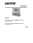
1
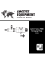
EQUIPMENT OPERATION MANUAL Loctite® Series 9000 Rotospray Pump 983330 Table of Contents 1 2 3 4 5 6 7 8 9 10 11 Page No. Warnings & Precautions . . . . . . . . . . . . . . . . . . . . . . . . . . .2 Introduction . . . . . . . . . . . . . . . . . . . . . . . . . . . . . . . . . . . . .3 Items Supplied . . . . . . . . . . . . . . . . . . . . . . . . . . . . . . . . . . .3 Installation Instructions and Required Controls . . . . . . . .4 View of Rotospray Pump with Components Labeled . . . . . . .5 Theory of Operation . . . . . . . . . . . . . . . . . . . . . . . . . . . . . .6 Operation Priming the Pump . . . . . . . . . . . . . . . . . . . . . . . . . . . . . . . . .7 Adjusting Pump Dispense Volume . . . . . . . . . . . . . . . . . . . . .7 Maintenance . . . . . . . . . . . . . . . . . . . . . . . . . . . . . . . . . . . .8 Pump Replacement Procedure . . . . . . . . . . . . . . . . . . . . . . .9 Troubleshooting General . . . . . . . . . . . . . . . . . . . . . . . . . . . . . . . . . . . . . . . .10 Replacement Parts and Assemblies . . . . . . . . . . . . . . . . .11 Phone Numbers for Help . . . . . . . . . . . . . . . . . . . . . . . . . . .11 Information on Pump Rebuilding Program . . . . . . . . . . . .12 Specifications Dimensions . . . . . . . . . . . . . . . . . . . . . . . . . . . . . . . . . . . . .13 Utilities Required . . . . . . . . . . . . . . . . . . . . . . . . . . . . . . . . .14 Weights . . . . . . . . . . . . . . . . . . . . . . . . . . . . . . . . . . . . . . . .14 Pressure Ratio of Pump . . . . . . . . . . . . . . . . . . . . . . . . . . .14 Warranty . . . . . . . . . . . . . . . . . . . . . . . . . . . . . . . . . . . . . .15 List of Figures Figure 1 2 3 4 Description View of Rotospray Pump with Components Labeled Rotospray Pump Operating Sequence Adjusting the Amount Dispensed Dimensions Page 5 6 7 13 1 1 Warnings and Precautions • OBSERVE ALL WARNINGS. READ and UNDERSTAND all instructions in the manual before attempting to install and operate this equipment. • This equipment has been designed and tested for use with Loctite® anaerobic products. • DO NOT USE equipment for other than intended use. • BE SURE that all adhesives, solvents, or fluids used are chemically compatible with the wetted parts of the equipment. • ALWAYS READ the Material Safety Data Sheet(s) before using adhesives, solvents, or any other chemicals in this equipment. COMPLY with ALL WARNINGS and SAFETY INSTRUCTIONS AS STATED. • ALWAYS WEAR protective eye wear, gloves, clothing, and respirator as recommended in this manual or the Material Safety Data Sheet(s). • Any misuse of the equipment or accessories, such as over-pressurizing, modifying parts, using incompatible chemicals, adhesives, or worn, damaged or not recommended parts, can cause rupture or breakage and result in fluid injection, splashing in the eyes or on the skin, or other serious injury or property damage. • NEVER alter or modify any part of this equipment. Doing so will void the warranty and could result in a malfunction. • CHECK the equipment regularly and repair or replace worn or damaged parts immediately. • NEVER exceed the recommended working pressure or the maximum air inlet pressure stated on the equipment or in the manual. • Properly ground all electrical components as recommended in the manual or technical data. • Always KEEP HANDS and FINGERS away from moving parts to reduce the risk of injury. • ALWAYS RELIEVE any pressure and turn off all power sources when checking or servicing any part of the equipment to reduce the risk of serious injury. • RETAIN THIS MANUAL FOR FUTURE REFERENCE. 2 2 Introduction The Loctite® Series 9000 Rotospray Pump will apply a metered amount of Loctite® anaerobic products to a Rotospray centrifugal force dispensing head. The Loctite Series 9000 Rotospray Pump is pneumatically operated and needs a 4-way pneumatic valve to control the pneumatic signals. The Loctite Series 9000 Rotospray Pump is usually part of a system that consists of the following components: 1. A gravity reservoir to supply product to the Loctite Rotospray Pump. 2. The Loctite Rotospray Pump itself. 3. A Rotospray centrifugal force dispense head. 4. A product tube between the pump and dispense head. 5. An electro-pneumatic or pneumatic control system. This manual will cover the Loctite Series 9000 Rotospray Pump part number 983330 only. The Loctite Series 9000 Rotospray Pump is designed to pump anaerobic materials with viscosity <100,000cps that can be gravity fed to the pump. The pump displacement range is 0.02 cc to 0.40 cc. Typical Loctite® Products are: Loctite product 271™, 277, 620, 635, 640, 11264, 11358, 11747, and 12019. The Loctite Rotospray Pump is not suitable for dispensing moisture cure products such as RTV Silicones or Cyanoacrylates. Because The Loctite Rotospray Pump is pneumatic, the only utility needed is compressed air. See the specifications on page 14 for the air quality requirements. Because anaerobic products are being dispensed, the parts which come in contact with the Loctite Anaerobic products are made as inert as possible. This helps prevent product curing within the system. In addition, the pump is designed with a minimum of dead areas or close clearances where anaerobic curing can start. Items Supplied: 993330 Loctite Series 9000 Rotospray Pump includes: Packaging and Inserts. (1) Loctite Rotospray Pump consisting of a pump section and an actuator section. (1) Mounting Bracket (983335). (1) Feedline Accessory Kit (983356). (1) Air Line Kit (983482). (1) Instruction Manual (983355). Note: See the Spare Parts List on page 11 for available spare parts. 3 3 Installation Inspection Before Installation The Loctite Rotospray Pump was inspected before shipment. Check the items in the shipping container against the list on Page 3 of this Manual. After removing the items from the shipping container inspect them for visible damage. Promptly report any damaged or missing parts to both the shipper and your Loctite representative. CAUTION: DO NOT REMOVE ANY ITEMS THAT ARE SEALED IN PLASTIC BAGS UNTIL THEY ARE TO BE USED AS THEY MAY BECOME CONTAMINATED RESULTING IN PERFORMANCE PROBLEMS. Installation Locate the pump so that: 1. The pump axis is horizontal. 2. The pump is at least 12 inches (300 mm) below the outlet of the gravity feed reservoir. 3. The pump is at approximately 4 inches (100 mm) below the centerline of the Rotospray centrifugal force dispensing head. 4. There is enough clearance to allow easy access to the outlet fitting. 5. There is enough clearance to allow easy access to the control air fittings. 6. The Rotospray centrifugal force dispensing head is within the range of the outlet tubing. Install the pump assembly into the Mounting Bracket (Part no. 983335). Secure the Bracket to the mounting surface with suitable fasteners. See Fig. 4 on page 13 for the bracket mounting hole dimensions and overall pump dimensions. Other Controls 1. The pump requires a 4-way pneumatic valve to operate. The valve should have a Cv of 0.5 and 1/8 NPT ports. 2. The pneumatic valve shall have both Manual and Automatic modes of operation. 3. A timing device will be required to operate 4-way valve that controls the pump. Connecting Air and Product Lines 1. Install the air line fittings into the 1/8 NPT ports in the pneumatic actuator. 2. Connect the normally not passing control valve port to the actuator port closest to the adjustment knob, (“Dispense” port on actuator). 3. Connect the normally passing control valve port to the actuator port farthest from the adjustment knob, (“Retract” port on actuator). 4. Connect 3/8-inch OD tubing from the product reservoir to the pump inlet. 5. Connect 1/4-inch OD tubing from the pump outlet to the applicator being used. 4 4 Installation, cont. STROKE ADJUSTER KNOB CONTROL AIR "DISPENSE" PORT PRODUCT INLET FITTING CONTROL AIR "RETRACT" PORT LOCKING RING PRODUCT OUTLET FITTING PUMP ASSEMBLY (983117) ACTUATOR ASSEMBLY (983116) MOUNTING BRACKET (983335) Fig. 1 View of the Pump with Component Labeled. 5 4 Theory of Operation The Loctite Series 9000 Rotospray Pump is a pneumatically-operated piston pump. It has a single ball type check valve at the outlet and a flooded inlet. The piston stroke is adjustable to control the amount of product dispensed. Fig. 2 below shows the sequence of operation: PISTON RETRACTED, CHECK BALL ON SEAT, METERING CYLINDER FILLED WITH PRODUCT. PISTON MOVING FORWARD, CHECK BALL OFF SEAT, PRODUCT DISPENSED. PISTON MOVING BACK, CHECK BALL ON SEAT VACUUM FORMED IN METERING CYLINDER. PISTON FULLY RETRACTED, CHECK BALL ON SEAT, METERING CYLINDER IS REFILLED WITH PRODUCT. PUMP READY FOR ANOTHER DISPENSE. Fig. 2 Rotospray Pump Operating Sequence 6 5 Operation Priming the Pump (first time use) 1. Set the pump stroke to maximum. 2. Move the pump piston to the fully retracted position. 3. Fill the reservoir with product. 4. Disconnect the 3/8-inch OD tube from the pump inlet. 5. Let the product flow to within 1/2-inch of the end of the 3/8-inch tube, then reconnect the tube to the pump inlet. 6. Cycle the pump. 7. Continue to cycle the pump until air-free product flows at the dispense point. Adjusting Pump Dispense Volume The black knob on the back of the pump is used to set the stroke of the pump which controls the amount of product dispensed per cycle. The knob should be turned fully clockwise then counter clockwise one full turn. You should then cycle the pump and check to see if the proper amount of product is being dispensed. Continue to adjust the knob until the desired amount is dispensed. Turning the knob clockwise reduces the amount dispensed and turning counterclockwise increases the amount. Plus and minus arrows on the stroke adjustment knob indicate the volume increase and decrease directions. MORE LESS STROKE ADJUSTER KNOB Fig. 3 Adjusting the Amount Dispensed 7 6 Maintenance Routine 1. Inspect air tubing, product tubing, and fittings for cracks, kinks or breaks and replace, as required. 2. Drain the air line filter bowl, if necessary. Idle Time 1. If the pump is in daily use, you do not need to service the pump or product tubing to prevent product curing unless a contaminant is introduced into the system. 2. The pump and tubing can be left idle for as long as one (1) month without curing under normal temperature (70° - 80°F). 3. If the pump is to be idle for longer than one (1) month, both the pump and the product lines should be serviced. Remove and replace product feed lines. Return the pump to a Loctite Service Center for cleaning and/or rebuilding. 4. If a gravity feed reservoir is being used, refer to the reservoir manual for idle time information. 8 6 Maintenance, cont. Replacing The Pump Or Actuator Module The rotospray pump consists of a pump module (part no. 983117) and an actuator module (part no. 983116). In most cases, the pump module is the one replaced. WARNING: Failure to correctly change out the pump module(s) will result in DAMAGE. No tools are required to connect or disconnect the pump from actuator. If any forceful effort is required, the assembly is not correct and the instructions should be reviewed. To Disassemble 1. Shut off air supply and relieve pressure from air lines. 2. Disconnect the air lines and product feed lines from the pump module. Elevate the feed line above the reservoir to prevent product leakage from the feed line. 3. Position and hold the pump assembly so that the stroke adjuster knob is facing you with air line connectors pointing straight up (12 o’clock). 4. Rotate the stroke adjuster knob counterclockwise to the full open position. 5. Rotate the knurled black locking ring clockwise by hand until it bottoms out or stops turning. 6. Gently push the pump module towards the actuator module and rotate the pump module clockwise approximately 90 degrees until it stops. 7. Disengage the pump module from the actuator module by pulling them apart. To Assemble 1. Push stroke adjuster knob in to advance pin connector. 2. Carefully position a new pump module onto the actuator module; the feed line connector should be at (3 o’clock) position, and push together until fully seated. 3. Rotate the pump module counterclockwise approximately 90 degrees or until it stops. 4. Rotate the black locking ring by hand counterclockwise until tight against face of the actuator. 5. Reconnect product feed lines and air lines to pump assembly and set stroke adjuster knob to dispense desired amount. 9 7 Troubleshooting Possible problems and solutions for the Series 9000 Rotospray Pump. Problem Pump does not dispense product and the Stroke Adjuster Knob does not move when the pump is cycled. Troubleshooting Guide Cause No air supply. Turn on air supply. Low air pressure. Adjust air pressure to at least 60 psi. Stroke Adjuster Knob set to zero stroke. Reset Stroke Adjuster Knob. Pump air actuator defective. Replace actuator. Control valve faulty. Replace control valve. Control logic problem. Check program and components. Cured product in pump. Replace pump. Pump does not dispense product and the Stroke Adjuster Knob moves very slowly when the pump is cycled. Cured product in outlet tubing or applicator. Replace tubing or applicator. Pump does not dispense product but the Stroke Adjuster Knob moves normally when the pump is cycled. Product reservoir empty. Pump is air bound. Refill reservoir. Reprime pump and check pump inlet fittings. Cured product in inlet tubing or fittings. Replace tubing or fittings. Pump check valve defective. Replace pump. Pump check valve defective. Replace pump. Reposition pump so that it is about 4 inches (100 mm) below the dispenser. Do not shake product bottle before filling reservoir. Mount pump as close as possible to dispenser. Product leaks from dispenser. Dispenser is located at a lower level than the pump. Air in product. Pump outlet tubing too long. Pump outlet tubing expands on pump cycling. All four (4) Items just above. 10 Solution Change original 1/4-inch OD polyethylene tubing to 1/4-inch OD nylon tubing Loctite Part No. 999488. Modify process to reduce drool. Change timing on rotospray spin time to get clean dispense. 8 Replacement Parts and Assemblies The following is a list of recommended parts or assemblies that may be required to service the Series 9000 Pump: Item 1. 2. 3. 4. 5. 6. 7. 8. Description Loctite Part No. Pump assembly 983117 Actuator Assembly 983116 Tubing 1/4-inch OD poly 981821 (for pump outlet). Tubing 3/8-inch OD poly 981866 (for pump inlet). Male connector, 1/4 T x 1/8 NPT, 991733 nylon (for pump outlet). Male connector, 3/8 T x 1/4 NPT, 999635 nylon (for pump inlet). Tubing 1/4-inch OD nylon 981994 (for pump outlet). Mounting Bracket 983335 Qty. 1 1 10 m 10 m 1 1 10 m As Req’d. Phone Numbers for Help: Questions regarding installation, operation, or safety should be addressed to: Loctite Corporation Technical Information Department 1001 Trout Brook Crossing Rocky Hill, Connecticut 06067 U.S.A. Telephone: 1-800-LOCTITE (1-800-562-8483) or 860-571-5100. 11 9 Series 9000 Pump Rebuilding Program The Series 9000 Pump is not field serviceable. Our rebuilding process ensures that the pump is free of contaminants and assembled to proper specifications reducing the possibly of a premature failure or unsatisfactory performance with Loctite products. This is accomplished by: • Ultrasonically cleaning the parts in the proper solvents for a predetermined time. • Pretreating all the wetted components to ensure a passive surface. • Using proper replacement parts. • Reassembling the pump in a clean room environment using proper techniques and torque specifications. To participate in this program, you will need to purchase and have on hand a pump assembly. At the recommended time intervals, you should replace the current pump assembly with the new assembly and return the used pump to the Loctite Equipment Service Department. A rebuilt pump will be shipped to you within five to ten working days after the receipt of your purchase order. All parts and labor are included in the price given to you to rebuild your pump. The rebuilt pump carries a ninety day warranty. For further information on participating in this rebuild program, please contact us at: Telephone: 1-800-LOCTITE (1-800-562-8483) or 860-571-5100. 12 10 Specifications 2.50 .50 2.50 2.06 4.20 1.63 REF. .44 .38 1.50 .50 1.88 DIAMETER .34 DIAMETER 7/16 HEX 9.15 1.35 DIAMETER Fig. 4 Dimensions 13 13 Specifications, cont. Utilities Required: Compressed air: 60 psig to 90 psig, filtered to 5 microns, dry (no condensing moisture). Lubricated air not required. Dimensions: See Fig. 4 on page 13. Product Viscosity Range: 100 cp - 100,000 cp Cycle Rate: Two Cycle per second maximum. Amount of product dispensed per stroke: Minimum = 0.02 cc. Maximum = 0.40 cc. Weight: 1.7 lbs. Calculated Pressure Ratio for Loctite Part No. 983330 Series 9000 Rotospray Pump: Item Pump 14 Calculated Pressure Ratios Air cylinder diameter Device diameter 1.125 inch 0.45 inch w/ double 0.50 inch rod (pump piston) Ratio 5.0 : 1 14 Equipment Warranty Loctite expressly warrants that all products referred to in this Instruction Manual under Loctite Series 9000 Rotospray Pump 983330 (hereafter called “Products”) shall be free from defects in materials and workmanship. Liability for Loctite shall be limited, at its option, to replacing those Products which are shown to be defective either in materials or workmanship or to credit to the purchaser the amount of the purchase price thereof (plus freight and insurance charges paid therefor by the user). The purchaser’s sole and exclusive remedy for breach of warranty shall be such replacement or credit. A claim of defect in materials or workmanship in any Products shall be allowed only when it is submitted to Loctite in writing within one month after discovery of the defect or after the time the defect should have reasonably have been discovered and in any event, within twelve months after the delivery of the Products to the purchaser. No such claim shall be allowed in respect of Products which have been neglected or improperly stored, transported, handled, installed, connected, operated, used or maintained or in the event of unauthorized modification of the Products including; where products, parts or attachments for use in connection with the Products are available from Loctite, the use of products, parts or attachments which are not manufactured by Loctite. No Products shall be returned to Loctite for any reason without prior written approval from Loctite, Products shall be returned freight prepaid in accordance with instructions from Loctite. NO WARRANTY IS EXTENDED TO ANY EQUIPMENT THAT HAS BEEN ALTERED, MISUSED, NEGLECTED, OR DAMAGED BY ACCIDENT, OR IF THE SYSTEM IS USED TO DISPENSE ANY LIQUID MATERIAL OTHER THAN LOCTITE CORPORATION PRODUCTS. EXCEPT FOR THE EXPRESS WARRANTY CONTAINED IN THIS SECTION, LOCTITE MAKES NO WARRANTY OF ANY KIND WHATSOEVER, EXPRESS OR IMPLIED, WITH RESPECT TO THE PRODUCTS. ALL WARRANTIES OR MERCHANTABILITY, FITNESS FOR A PARTICULAR PURPOSE, AND OTHER WARRANTIES OF WHATEVER KIND (INCLUDING AGAINST PATENT OR TRADEMARK INFRINGEMENT) ARE HEREBY DISCLAIMED BY LOCTITE AND WAIVED BY THE PURCHASER. THIS SECTION SETS FORTH EXCLUSIVELY ALL OF LOCTITE LIABILITY TO THE PURCHASER IN CONTRACT, IN TORT OR OTHERWISE IN THE EVENT OF DEFECTIVE PRODUCTS. WITHOUT LIMITATION OF THE FOREGOING, TO THE FULLEST EXTENT POSSIBLE UNDER APPLICABLE LAWS, LOCTITE EXPRESSLY DISCLAIMS ANY LIABILITY WHATSOEVER FOR ANY DAMAGES INCURRED DIRECTLY OR INDIRECTLY IN CONNECTION WITH THE SALE OF USE OF, OR OTHERWISE IN CONNECTION WITH, THE PRODUCTS, INCLUDING, WITHOUT LIMITATION, LOSS OF PROFITS AND SPECIAL, INDIRECT OR CONSEQUENTIAL DAMAGES, WHETHER CAUSED BY LOCTITE NEGLIGENCE OR OTHERWISE 15 Loctite Americas 1001 Trout Brook Crossing Rocky Hill, CT 06067-3910 Loctite Corporation One Northfield Plaza, 5600 Crooks Rd. Suite 105 Troy, Michigan 48098 Loctite Canada Inc. 2225 Meadowpine Blvd. Mississauga, Ontario L5N 7P2 Loctite Company de México, S.A. de C.V. Calzada de la Viga s/n, Fracc. Los Laureles Loc. Tulpetlac, C.P. 55090 Ecatepac de Morelos, Edo. de México México Loctite and 271 are trademarks of Loctite Corporation, U.S.A. © Copyright 1999. Loctite Corporation. All rights reserved. P/N983355 Rev.A – 9/99