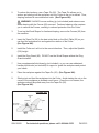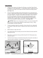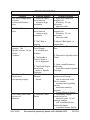
1
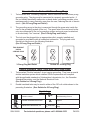
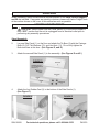
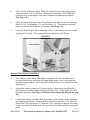
INDUSTRIAL
SHAPER/ROUTER
Model 95668
Set up and Operating Instructions
Visit our website at: http://www.harborfreight.com
Read this material before using this product.
Failure to do so can result in serious injury.
Save this manual.
Copyright© 2007 by Harbor Freight Tools®. All rights reserved. No portion of this manual or any artwork
contained herein may be reproduced in any shape or form without the express written consent of Harbor
Freight Tools. Diagrams within this manual may not be drawn proportionally. Due to continuing improvements, actual product may differ slightly from the product described herein. Tools required for assembly
and service may not be included.
For technical questions or replacement parts, please call 1-800-444-3353.
Revised Manual 10d
PRODUCT SPECIFICATIONS
Electrical Requirements
Spindle Diameter
Spindle Thread
Spindle Travel
Router Collets
Maximum Cutting Diameter
Table Size
Footprint
Miter Guide
Fence Dimensions
Overall Dimensions
Gross Weight
110 VAC / 60 Hz / 10.54 Amps (With Load)
Motor Size: 1 HP / Single Phase
Motor RPM: 3450
Spindle Speed: 11,000
Power Cord Length: 70”
Power Cord Specifications: SJT 16 AWG x 3C
Plug Type: 3 Prong / Grounded
1/2”
12mm x 1.5 pitch, fine thread
7/8”
¼” and ½” (included)
2-7/8”
24” Wide x 19” Deep
18-7/8” Wide x 16-5/8” Deep
0 ~ 60° Left to Right
9/16” Long x 11-3/4” Wide x 2-3/4” High (Qty. 2)
26-1/8” Long x 27-1/2” Wide x 36-1/2” High
187.5 Lb.
SAVE THIS MANUAL
You will need this manual for the safety warnings and precautions, assembly,
operating, inspection, maintenance and cleaning procedures, parts list and assembly
diagram. Keep your invoice with this manual. Write the invoice number on the
inside of the front cover. Keep this manual and invoice in a safe and dry place for
future reference.
GENERAL SAFETY RULES
WARNING!
READ AND UNDERSTAND ALL INSTRUCTIONS
Failure to follow all instructions listed below may result in
electric shock, fire, and/or serious injury.
SAVE THESE INSTRUCTIONS
WORK AREA
1.
Keep your work area clean and well lit. Cluttered benches and dark areas invite accidents.
2.
Do not operate the Wood Shaper in explosive atmospheres, such as in the
presence of flammable liquids, gases, or dust. Power equipment creates sparks which may ignite the dust or fumes.
3.
Keep bystanders, children, and visitors away while operating power
equipment. Distractions can cause you to lose control. Protect others in the work
REV 10d
SKU 95668
For technical questions, please call 1-800-444-3353
PAGE 2
area from debris such as chips and sparks. Provide barriers or shields as needed. Children and visitors should never be in the work area.
ELECTRICAL SAFETY
1.
Grounded tools must be plugged into an outlet properly installed and
grounded in accordance with all codes and ordinances. Never remove the grounding prong or modify the plug in any way. Do not use any adapter plugs. Check with a qualified electrician if you are in doubt as to whether the outlet is properly grounded. If the tools should electrically malfunction or break down, grounding provides a low resistance path to carry electricity away from the user.
2.
Avoid body contact with grounded surfaces such as pipes, radiators,
ranges, and refrigerators. There is an increased risk of electric shock if your
body is grounded.
3.
Do not expose power tools to rain or wet conditions. Water entering power equipment will increase the risk of electric shock.
4.
Do not abuse the Power Cord. Never use the Power Cord to pull the Plug from an outlet. Keep the Power Cord away from heat, oil, sharp edges, or moving parts. Replace damaged Power Cords immediately. Damaged
Power Cords increase the risk of electric shock.
PERSONAL SAFETY
1.
Stay alert. Watch what you are doing, and use common sense when operating the Wood Shaper. Do not use the tool while tired or under the influence of drugs, alcohol, or medication. A moment of inattention while operating power tools may result in serious personal injury.
2.
Dress properly. Do not wear loose clothing or jewelry. Contain long hair. Keep your hair, clothing, and gloves away from moving parts. Loose clothes, jewelry, or long hair can be caught in moving parts.
3.
Use the right product for the job. Do not attempt to force small equipment to do the work of larger industrial equipment. There are certain applications for which this product was designed. It will do the job better and safer at the rate and capacity for which it was designed. Do not modify this product, and do not use this product for a purpose for which it was not designed.
4.
Avoid accidental starting. Be sure the Power Switch is off before plugging
SKU 95668
For technical questions, please call 1-800-444-3353
PAGE 3
in. Plugging in power equipment with the Power Switch on, invites accidents.
5.
Remove adjusting keys or wrenches before turning the power tool on. A wrench or a key that is left attached to a rotating part of the Wood Shaper may result in personal injury.
6.
Do not overreach. Keep proper footing and balance at all times. Proper footing and balance enables better control of the Wood Shaper in unexpected
situations.
7.
Use safety equipment. Always wear ANSI-approved safety impact eye goggles. Dust mask or respirator, and hearing protection must be used for appropriate conditions.
TOOL USE AND CARE
1.
Do not force the Wood Shaper. Use the correct tool for your application. The correct tool will do the job better and safer at the rate for which it is designed.
2.
Do not use the Wood Shaper if the Power Switch does not turn it on or off. Any tool that cannot be controlled with the Power Switch is dangerous and must be replaced.
3.
Disconnect the Power Cord Plug from the power source before making any
adjustments, changing accessories, or storing the Wood Shaper. Such preventive safety measures reduce the risk of starting the tool accidentally.
4.
Store idle tools and equipment out of reach of children and other untrained persons. Tools and equipment are dangerous in the hands of untrained users.
5.
Maintain this product with care. Keep the Wood Shaper and its Table clean and in proper working order. Properly maintained tools and equipment are easier to control. Do not use damaged tools and equipment. Tag damaged tools
and equipment “Do not use” until repaired.
6.
Check for misalignment or binding of moving parts, breakage of parts,
and any other condition that may affect the Wood Shaper’s operation. If
damaged, have the tool serviced before using. Many accidents are caused
by poorly maintained tools.
7.
Use only accessories that are recommended by the manufacturer for your model. Accessories that may be suitable for one product may become
hazardous when used on another product.
SKU 95668
For technical questions, please call 1-800-444-3353
PAGE 4
SERVICE
1.
Tool service must be performed only by qualified repair personnel. Service or maintenance performed by unqualified personnel could result in a risk of injury.
2.
When servicing a tool, use only identical replacement parts. Follow instructions in the “Inspection, Maintenance, And Cleaning” section of this manual. Use of unauthorized parts or failure to follow maintenance instructions may create a risk of electric shock or injury.
SPECIFIC SAFETY RULES
1.
Maintain labels and nameplates on the Wood Shaper. These carry important information. If unreadable or missing, contact Harbor Freight Tools for a replacement.
2.
Avoid unintentional starting. Make sure you are prepared to begin work before turning on the Wood Shaper.
3.
Do not force the Wood Shaper. This tool will do the work better and safer at the speed and capacity for which it was designed.
4.
WARNING! Keep hands and fingers away from the cutting area. Use a “push stick” (not included) when necessary.
5.
Never leave the Wood Shaper unattended when it is plugged into an electrical outlet. Always unplug the unit from its electrical outlet before leaving.
6.
Industrial applications must follow OSHA guidelines.
7.
Never stand on the Wood Shaper. Serious injury could result if the unit is tipped.
8.
Always unplug the Wood Shaper from its power supply source before performing any inspection, maintenance, or cleaning procedures.
9.
Keep all guards in place and in proper working order.
10.
Never place your hands within 12 inches of the Cutters. Never pass your hands directly over or in front of the Cutter. As one hand approaches the 12 inch radius point, move it in an arc motion away from the Cutter to the outfeed side and reposition that hand more than 12 inches beyond the Cutter.
11.
Do not shape stock shorter than 12 inches without special fixtures or jigs (not included). Where practical, shape longer stock and cut to size.
SKU 95668
For technical questions, please call 1-800-444-3353
PAGE 5
12.
Keep the Cutters on the underside of the workpiece whenever possible. This provides a distance guard for the operator.
13.
Unplug the Wood Shaper, and always rotate the Spindle by hand to test any new setup to ensure proper Cutter clearance before starting the Wood Shaper.
14.
When shaping contoured work and using a Rub Collar, never start shaping at a corner. See the “Rub Collar” section further on in this manual. The danger of kickback is increased when the stock has knots, holes, or foreign objects in it.
15.
Always run warped stock through a jointer before you run it through the Wood Shaper.
16.
Keep any unused portion of the Cutter below the Table surface.
17.
Never attempt to remove too much material in one pass. Several light
passes are safer and give a cleaner finish.
18.
In most applications, it is recommended to use a “push stick” (not included)
as a safety device. In other situations, using a push stick can be dangerous.
If the push stick comes in contact with the Cutter on the end grain it can be
violently propelled from your hand, potentially causing serious injury. It is
recommended to use some type of fixture, jig, or hold-down device as a safer
alternative.
19.
Always make sure the Cutter is positioned in the correct direction before
starting the Wood Shaper, and always feed against the rotation of the
Cutter.
20.
Always use the Overhead Guard when the Fence is not in place.
21.
Never operate the Wood Shaper without the second Lock Nut in place over the Spindle Nut.
22.
Turn off the Wood Shaper and allow the unit to stop on its own if the workpiece is to be backed out of an uncompleted cut.
23.
Never attempt to remove material stuck in the moving parts of the Wood Shaper while it is plugged in and running.
24.
Make sure the Table is clear with the exception of the workpiece to be shaped.
25.
The Wood Shaper is designed for shaping wood workpieces only. Do not attempt to use the Wood Shaper to cut metal or other nonwood materials.
SKU 95668
For technical questions, please call 1-800-444-3353
PAGE 6
26.
Use the right tool for the job. Do not attempt to force a small tool or
attachment to do the work of a larger industrial tool. There are certain
applications for which this tool was designed. It will do the job better and more
safely at the rate for which it was intended. Do not modify this tool, and do not
use this tool for a purpose for which it was not intended.
27.
WARNING! Some dust created by power sanding, sawing, grinding, drilling,
and other construction activities, contain chemicals known (to the State of
California) to cause cancer, birth defects or other reproductive harm. Some
examples of these chemicals are: lead from lead-based paints, crystalline silica
from bricks and cement or other masonry products, arsenic and chromium from
chemically treated lumber. Your risk from these exposures varies, depending on
how often you do this type of work. To reduce your exposure to these chemicals:
work in a well ventilated area, and work with approved safety equipment, such as
those dust masks that are specially designed to filter out microscopic particles.
(California Health & Safety Code 25249.5, et seq.)
28.
WARNING! People with pacemakers should consult their physician(s)
before using this product. Operation of electrical equipment in close proximity to
a heart pacemaker could cause interference or failure of the pacemaker.
29.
WARNING! The warnings, precautions, and instructions discussed in this
manual cannot cover all possible conditions and situations that may occur. The
operator must understand that common sense and caution are factors which cannot
be built into this product, but must be supplied by the operator.
SAVE THESE INSTRUCTIONS
Grounding
WARNING
Improperly connecting the grounding wire can result in
electric shock.
Check with a qualified electrician if you are in doubt as to
whether the outlet is properly grounded. Do not modify
the power cord plug provided with the tool. Never remove
the grounding prong from the plug. Do not use the tool if
the power cord or plug is damaged. If damaged, have it
repaired by a service facility before use. If the plug will not
fit the outlet, have a proper outlet installed by a qualified
electrician.
SKU 95668
For technical questions, please call 1-800-444-3353
PAGE 7
Grounded Tools: Tools with Three Prong Plugs
1.
Tools marked with “Grounding Required” have a three wire cord and three prong
grounding plug. The plug must be connected to a properly grounded outlet. If
the tool should electrically malfunction or break down, grounding provides a low
resistance path to carry electricity away from the user, reducing the risk of electric
shock. (See 3-Prong Plug and Outlet.)
2.
The grounding prong in the plug is connected through the green wire inside the
cord to the grounding system in the tool. The green wire in the cord must be the
only wire connected to the tool’s grounding system and must never be attached
to an electrically “live” terminal. (See 3-Prong Plug and Outlet.)
3.
The tool must be plugged into an appropriate outlet, properly installed and
grounded in accordance with all codes and ordinances. The plug and outlet
should look like those in the following illustration.
(See 3-Prong Plug and Outlet.)
THIS PRODUCT
USES A
3-PRONG PLUG
3-Prong Plug and Outlet
Outlets for 2-Prong Plug
Double Insulated Tools: Tools with Two Prong Plugs
1.
Tools marked “Double Insulated” do not require grounding. They have a special
double insulation system which satisfies OSHA requirements and complies
with the applicable standards of Underwriters Laboratories, Inc., the Canadian
Standard Association, and the National Electrical Code.
(See Outlets for 2-Prong Plug.)
2.
Double insulated tools may be used in either of the 120 volt outlets shown in the
preceding illustration. (See Outlets for 2-Prong Plug.)
Symbology
Double Insulated
Canadian Standards Association
Underwriters Laboratories, Inc.
SKU 95668
V~
A
Volts Alternating Current
Amperes
No Load Revolutions per Minute
n0 xxxx/min. (RPM)
For technical questions, please call 1-800-444-3353
PAGE 8
UNPACKING
When unpacking, check to make sure all the parts shown on the Parts Lists on pages 27
and 28 are included. If any parts are missing or broken, please call Harbor Freight Tools
at the number shown on the cover of this manual as soon as possible.
ASSEMBLY INSTRUCTIONS
1.
CAUTION! Always make sure the Power Switch (5) of the Wood Shaper is
in its “OFF” position and the unit is unplugged from its electrical outlet prior to
performing any assembly procedures.
Stand Assembly:
2.
Lay one Side Panel (1) on the floor and attach the Tie Bars (2) with the Carriage
Bolts (9), 3/8” Flat Washers (10), and Hex Nuts (11). Do not fully tighten the
Bolts and Nuts at this time. (See Figures D, and E.)
3.
Attach the second Side Panel (1) to the assembly. (See Figures D and E.)
FIGURE D
SIDE PANEL
(1)
CARRIAGE BOLTS (9)
3/8” FLAT WASHERS (10)
HEX NUTS (11)
SIDE PANEL
(1)
TIE BAR
(2)
TIE BAR
(2)
4.
RUBBER FEET
(3)
Attach the four Rubber Feet (3) to the bottom of the Side Panels (1).
(See Figure F.)
FIGURE E
SKU 95668
FIGURE F
For technical questions, please call 1-800-444-3353
PAGE 9
5.
Place the Wood Shaper’s Work Table (52) upside down on two sturdy blocks that are at least 3-1/2” off the floor. Make sure the Spindle (105) DOES NOT touch the floor or the weight of the Wood Shaper may damage the Spindle.
(See Figure G.)
6.
Place the Stand assembly on the Wood Shaper and attach it with the Carriage Bolts (9), 3/8” Flat Washers (10), and Hex Nuts (11). Then have an assistant help you turn the Wood Shaper unit upright. (See Figure G.)
7.
Level the Wood Shaper with a carpenter’s level. If necessary, move the Stand slightly until it is level. Then, tighten all Bolts and Nuts on the Stand.
FIGURE G
STAND ASSEMBLY
(28)
(28)
(28)
(66)
(66)
WORK TABLE
(52)
Optional Table Spacer Installation:
1.
Your shaper comes with a Table Spacer Installation Kit that will enable you
to make shallow cuts and utilize the upper blade area of most router bits with
shanderd-length shanks. This is an optional feature that is not required for most
applications.
2.
Unplug the shaper power cord. Remove the four table corner Hex Bolts (66),
then remove the three Spindle Housing Hex Bolts (95). Lift the Table (52) off of
the stand assembly. (See Figure G above and the assembly diagram on page
29.)
3.
Locate the package, (included with your shaper), that contains all the hardware
for installing the spacers. There should be five M12 Long Bolts (151), two M12
Short Bolts (152) and seven 1/2” Spacers (150). Position one spacer over each
of the four corner bolt holes and one over each of the three spindle housing bolt
holes.
REV 07j
SKU 95668
For technical questions, please call 1-800-444-3353
PAGE 10
3.
Carefully place the Table (52) over the Table Legs (28). Secure the Table (52)
using two Short Bolts (152) and washers (65) in the front of the shaper, and five
Long Hex Bolts (151) and Washer (65) for the rear corners and for the spindle
housing. (See Figure G above and the assembly diagram on page 29.)
Installing The Fences:
1.
Using the Philips Head Screws (12) and Washers (13), install each Fence (60)
to the Right and Left Fence Bodies (57, 59). Make sure the Screwheads are
countersunk completely below the surface of the Right and Left Fence Bodies
(57, 59). (See Figure H.)
Installing The Safety Guard:
1.
Connect the Hold Down Bar (77) to the Hex Post (79) with two Hex Bolts (75) and two Flat Washers (76). (See Figure I.)
2.
Connect the Hold Down Bar (77) to the Ring Guard (85) with two Philips Head Screws (78) and two Hex Nuts (84) (See Figure I.)
3.
Position the Hold Down Bar (77) and Ring Guard (85) on the Housing Bracket (87) and install the Hex Post (79) on the Mounting Bracket (82). (See Figure I.)
FIGURE H
FIGURE I
RING GUARD
(85)
HOLD DOWN BAR
(77)
PHILIPS HEAD SCREWS (78)
HEX NUTS (84)
FENCE
(60)
RIGHT FENCE BODY
(not Shown)
(57)
LEFT FENCE BODY
(59)
HOUSING
BRACKET
(87)
MOUNTING BRACKET
(82)
PHILIPS HEAD SCREWS (12)
WASHERS (13)
Installing The Spindle:
1.
Prior to installation, make sure to remove any oil, grease, dirt and debris from
the Spindle (105), Draw Bar (121), and Spindle Housing (110) surfaces before
installing the Spindle. (See Figures J and K.)
REV 07j
SKU 95668
For technical questions, please call 1-800-444-3353
PAGE 11
2.
Thread one end of the Draw Bar (121) into the bottom end of the Spindle (105) approximately 10 to 15 turns until tight. (See Figure J.)
3.
Insert the Spindle/Draw Bar assembly into the Spindle Housing (110) from the top side of the Work Table (52). (See Figure K.)
4.
Thread the tapered Draw Bar Hex Nut (122) onto the end of the Draw Bar (121) under the Work Table (52), making sure the tapered side of the Hex Nut is facing upward. (See Figure L.)
5.
Place a wrench (not included) on the top end of the Spindle (105).
6.
Using an open-end wrench (not included), tighten the Draw Bar Hex Nut (122) while holding the Spindle (105) securely. DO NOT over-tighten the Draw Bar
Hex Nut. (See Figure M.)
FIGURE K
FIGURE J
SPINDLE
(105)
DRAW BAR
(121)
SPINDLE HOUSING
(110)
FIGURE M
FIGURE L
SPINDLE (105)
DRAW BAR HEX NUT
(122)
DRAW BAR HEX NUT
(122)
REV 07j
SKU 95668
For technical questions, please call 1-800-444-3353
PAGE 12
Router Bit Assembly:
1.
Prior to installation, make sure to remove any oil, grease, dirt and debris from
the Collet (103, 104), Draw Bar (121), and Spindle Housing (110) surfaces before installing a Router Bit.
2.
Remove the Spindle (105) as shown on page 12 of this manual.
(See Figures K, L, and M.)
3.
Insert the Collet (103, 104) into the Spindle Housing (110). (See Figure N.)
4.
Install the Router Bit (not included).
5.
Hold the flat edge on the Spindle Housing (110), and tighten the Collet Nut (102).
(See Figure O.)
6.
Rotate the assembly by hand, making sure the Collet (103, 104) and bit rotate freely on center.
7.
WARNING! When using a Router Bit (103, 104), operate the Wood Shaper only in a counterclockwise direction. Router Bits are designed to cut in the counterclockwise direction only. DO NOT operate the Wood Shaper in the clock-
wise direction. If this warning is ignored, the workpiece can kickback. The Collet Nut (102) can loosen and throw the Router Bit, causing severe injury.
SPINDLE HOUSING (110)
ROUTER BIT
(not included)
Collet (103, 104)
COLLET NUT
(102)
COLLET (103, 104)
SPINDLE HOUSING
FLAT EDGE
FIGURE N
FIGURE O
ADJUSTMENTS INSTRUCTIONS
1.
CAUTION! Always make sure the Power Switch (5) of the Wood Shaper is
in its “OFF” position and the unit is unplugged from its electrical outlet prior to
performing any adjustment procedures.
Fence Positioning:
1.
The two Fences (60) are independently adjustable to allow for different
SKU 95668
For technical questions, please call 1-800-444-3353
PAGE 13
shaping tasks. The Fences (60) can be set at different positions to remove
material from the entire edge of the wood stock or set at the same position to
shape part of the edge.
2.
Loosen the Lock Handle (61). (See Figure P.)
3.
Adjust the position of the Fence (60) by turning the Knob (64). (See Figure P.)
4.
Once the Fence (60) is in the desired position, re-tighten the Lock Handle (61).
(See Figure P.)
FIGURE P
FENCE
(60)
FENCE
(60)
LOCK HANDLE
(61)
KNOB
(64)
Fence Alignment:
1.
To align the Fences (60) so they are parallel with each other, use a straight edge that is long enough to span the entire length of the two Fences (60). (See
Figure Q.)
2.
If the Fences (60) are not parallel, place shims (not included) between the back of the Fence and the face of the Right or Left Fence Body
(57, 59). (See Figure Q.)
FENCE (60)
FENCE
(60)
STRAIGHT EDGE
(NOT INCLUDED)
FIGURE Q
SKU 95668
For technical questions, please call 1-800-444-3353
PAGE 14
Table Inserts:
1.
Table Inserts (53, 53A) are used to reduce wood chips falling into the machine which could cause flying debris. Using the smallest Table Insert also covers any unused portion of the bit below the surface of the Work Table (52).
(See Figure R.)
2.
Position, and snap in the Table Insert (53, 53A) you wish to use. (See Figure R.)
3.
Make sure the Table Insert (53, 53A) is seated and flush with the Work Table (52) surface. (See Figure R.)
FIGURE R
TABLE INSERT
(53, 53A)
WORK TABLE
(52)
Belt Adjustment:
1.
The Wood Shaper uses a Belt (123) on two Pulleys (113, 127) to compensate for different Belt positions as the Spindle (105) height is adjusted. To adjust the V-Belt:
Loosen the two Hex Head Screws (134). Slide the Motor (129) position to increase or decrease V-Belt (123) tension, so that the Belt is snug with about 1/4” deflection when pressed lightly with your finger. Then, retighten the Hex Head Screws. (See Figure S.)
FIGURE S
V-BELT (123)
HEX HEAD SCREW
(134)
MOTOR (129)
SKU 95668
For technical questions, please call 1-800-444-3353
PAGE 15
Cutter Direction:
1.
The Wood Shaper is capable of operating in two directions by the use of the Forward/Reverse Switch (144). It is very important that the workpiece be fed against the direction of the Cutter rotation. (Cutter not included)
(See Figure T.)
2.
When the Forward/Reverse Switch (144) is pointing to the FWD position, the Spindle (105) and Cutter rotate counterclockwise. (See Figure T.)
3.
When the Forward/Reverse Switch (144) is pointing to the REV position, the Spindle (105) and Cutter rotate clockwise. (See Figure T.)
4.
Always try to operate the Wood Shaper so the wood is cut from the underside. Underside cutting is much safer for the operator because when the wood is cut on the top side, the Cutter can lift and grab the wood and cause possible injury to the operator.
FORWARD/REVERSE SWITCH
(144)
FIGURE T
Cutter Installation:
1.
Slide the Cutter (not included) onto the Spindle (105), making sure the rotation is correct for the specific application.
SKU 95668
For technical questions, please call 1-800-444-3353
PAGE 16
2.
Place the required spacers, also called Rub Collars (98, 99, 100), onto the Spindle (105). (See Figure V.)
SPINDLE (105)
FIGURE V
RUB COLLARS
(98, 99, 100)
CUTTER
(NOT INCLUDED)
3.
Install the Safety Washer (97) and Upper Spindle Nut (96) securely. Tighten the Upper Spindle Nut with an open-end wrench while holding the Spindle (105) at the top with the provided Arbor Wrench (146). (See Figures W and X.)
4.
Check to make sure the Cutter (not included) will rotate in the correct direction.
FIGURE W
FIGURE X
ARBOR WRENCH
(146)
SAFETY WASHER (97)
UPPER
SPINDLE NUT
(96)
UPPER
SPINDLE NUT
(96)
Setting Spindle Height:
1.
Correct Spindle (105) height is crucial to most shaping applications. Make sure to use a piece of scrap wood to confirm the correct Spindle height before cutting expensive lumber.
2.
Loosen the Spindle Hand Knob (92) located on the side of the Wood Shaper.
(See Figure Y, next page.)
3.
Move the Spindle Height Knob (120) to the right to raise the Spindle (105) or to
SKU 95668
For technical questions, please call 1-800-444-3353
PAGE 17
the left to lower the Spindle (105). (See Figure Z.)
4.
Retighten the Spindle Hand Knob (92) on the side of the Wood Shaper. DO NOT overtighten the Knob. Only a small amount of tension is needed to keep the Spindle (105) from moving during operation. (See Figure Y.)
FIGURE Y
FIGURE Z
SPINDLE
HAND KNOB
(92)
SPINDLE
HEIGHT KNOB
(120)
Rub Collars:
1.
When shaping workpieces that have irregular shapes, Rub Collars (98, 99, 100) are a necessity. Some examples of when you would use a Rub Collar are raising arched or tombstone door panels, round table tops, or any other cut that needs to have its depth of cut limited.
2.
There are three set-up positions for Rub Collars (98, 99, 100):
A. Above the Cutter: This set-up is the safest and produces a most consistent result. The only drawback is that the cut is on the underside of the workpiece, out of view of the operator. However, if the workpiece lifts off the Work Table (52) you simply run it through a second time to finish the cut. (See Figure AA.)
RUB COLLAR
(98, 99, 100)
ABOVE
CUTTER
FIGURE AA
SKU 95668
For technical questions, please call 1-800-444-3353
PAGE 18
B. Between two Cutters: This set-up has the advantage of making two profile cuts in a single pass. Although there is a Rub Collar (98, 99, 100) beneath a Cutter, this set-up is safer than the previous set-up. Any lifting of the workpiece will still cause the Cutter to make an uneven cut. A second pass will correct the profile on the bottom edge, but the top profile will still have the gouge from lifting the workpiece into the Cutter. (See Figure BB.)
CUTTER
RUB COLLAR
(98, 99, 100)
BETWEEN
CUTTER
FIGURE BB
C. Below the Cutter: This set-up allows the cut to be viewed by the operator. However, it is also the most dangerous. Any slight lifting of the workpiece will cause the Cutter to make too deep of a cut. There is also increased risk of kickback. It is NOT recommended to shape with a Rub Collar below the Cutter. (See Figure CC.)
NOT RECOMMENDED
RUB COLLAR
(98, 99, 100)
CUTTER
BELOW
FIGURE CC
OPERATING INSTRUCTIONS
1.
SKU 95668
Use safety equipment. Always wear ANSI-approved safety impact eye goggles. Dust mask or respirator, and hearing protection must be used for appropriate conditions.
For technical questions, please call 1-800-444-3353
PAGE 19
Start Up:
1.
Once assembly is complete and all adjustments have been made, the Wood Shaper is ready for start up. Always pay attention to any unusual noises and vibrations on every start up, as well as making sure the Wood Shaper operates as intended.
2.
Make sure the Fences (60), any accessories, jigs, Spindle Cutter, or Router Bit
Collet Nut (102) being used are tight and no loose items are on the Work Table
(52).
3.
Make sure the Forward/Reverse Switch (144) is set to the correct direction for the Cutter installed.
4.
Plug the Wood Shaper’s Power Cord (22) into the nearest 110 volt, grounded, electrical outlet. Then, start the Wood Shaper by flipping the Power Switch (5) to the “ON” position.
5.
Once the machine is running, listen for any unusual noises. The Wood Shaper should run smoothly with little or no vibrations.
WARNING! If there is an unusual noise or vibration, shut off the machine immediately. DO NOT use the Wood Shaper any further until the problem(s) is corrected. If the problem(s) continues and cannot be easily identified, have a qualified service technician check out the machine.
To Set Up The Wooden Fences For Straight Shaping:
1.
Because the Wood Shaper’s Fences (60) are independently adjustable, you can
set up the machine to cut part or all of the workpiece edge.
2.
WARNING! DO NOT use the Miter Gauge (45) in conjunction with the Fences (60). The Fences may not be parallel to the miter slot, and binding of the
workpiece could result.
3.
To set up the Fences (60) for cutting material from the whole edge of the
workpiece, follow the steps below.
4.
Loosen the Lock Handle (61). (See Figure DD, next page.)
5.
Turn the Hand Knob (68) and adjust the infeed Fence (60) until the workpiece
contacts the Cutter at the desired location.
(See Figure DD, next page.)
SKU 95668
For technical questions, please call 1-800-444-3353
PAGE 20
6.
Tighten the Lock Handle (61) to lock the infeed Fence (60) in position.
(See Figure DD.)
FENCE
(60)
INFEED SIDE
FENCE
(60)
OUTFEED SIDE
FIGURE DD
LOCK HANDLE
(61)
HAND KNOB
(68)
7.
Adjust the outfeed Fence (60) so that it is located as far back from the front of the Work Table (52) as possible. (See Figure DD.)
8.
Turn on the Wood Shaper.
9.
Using a piece of scrap wood, advance the workpiece 8” into the Cutter and turn off the machine. DO NOT remove the workpiece from the infeed Fence (60).
(See Figure DD.)
10.
Once the Cutter has come to a complete stop, adjust the outfeed Fence (60)
so that it just touches the newly cut edge of the workpiece. Always follow the
direction of feed as shown below. (See Figure EE.)
(GUARD NOT SHOWN FOR CLARITY)
INPUT FEED
OUTPUT FEED
DIRECTION OF FEED
FIGURE EE
11.
Check to make sure all Aluminum Fence Lock Handles (61) are tight before proceeding to finish the cut. (See Figure DD.)
SKU 95668
For technical questions, please call 1-800-444-3353
PAGE 21
To Set Up The Aluminum Fences For Partial Edge Removal:
1.
WARNING! ALWAYS use the aid of a jig (not included) when shaping small or narrow workpieces. A jig will reduce the chance of your hands coming into contact with the Cutter.
2.
Loosen the Lock Handle (61). (See Figure DD.)
3.
Turn the Hand Knob (68) and adjust the infeed Fence (60) until the workpiece
contacts the Cutter at the desired location. (See Figure DD.)
4.
Retighten the Lock Handle (61) to lock the infeed Fence (60) in position. (See Figure DD.)
5.
Adjust the outfeed Fence (60) so that it comes into alignment with the infeed Aluminum Fence (60). (See Figure FF.)
6.
Place a straight edge against the infeed and outfeed Aluminum Fences (60) to check alignment. Once they are both in alignment, make sure the Lock Handle (61) is tightened.
7.
Always feed the wood against the rotation of the Cutter. Also, examine the grain on the side edge of the board. Whenever possible, run the board so the Cutter is cutting with the grain. (See Figure GG.)
GUARD NOT SHOWN FOR CLARITY
OUTPUT
FEED
GUARD NOT SHOWN FOR CLARITY
INPUT
FEED
DIRECTION OF FEED
DIRECTION OF FEED
FIGURE FF
FIGURE GG
Freehand Shaping:
1.
Freehand shaping is shaping without the aid of the Miter Gauge (45) or Aluminum
Fences (60). The most dangerous part of shaping freehand is beginning the cut, where the Cutter first contacts the workpiece. Often, the workpiece will tend to jerk or kickback, catching the operator off guard.
SKU 95668
For technical questions, please call 1-800-444-3353
PAGE 22
2.
To reduce this tendency, use a Taper Pin (56). The Taper Pin allows you to anchor and slowly pivot the workpiece into the Cutter as the cut is started. Thus, shaping freehand is more stable and safer. (See Figures HH).
WARNING! ALWAYS use an auxiliary jig (not included) and extreme care when shaping with the Fences (60) removed. Freehand shaping often requires
you to remove the Fences, resulting in reduced protection from the Cutter.
3.
To set up the Wood Shaper for freehand shaping, remove the Fences (60) from
the machine.
4.
Insert the Taper Pin (56) in the best suited hole on the Work Table (52) so you can feed the workpiece into and against the rotation of the Cutter.
(See Figures HH).
5.
Install the Cutter so it will cut in the correct direction. Then, adjust the Spindle (105) height.
6.
Install the Ring Guard (85). DO NOT use the Wood Shaper without the Ring Guard installed.
7.
Use a supplemental hold-down jig (not included), or you can use rubberized-
handle push blocks (not included) to support or guide the workpiece and protect your hands.
8.
Place the workpiece against the Taper Pin (56). (See Figures HH).
9.
Slowly pivot and feed the workpiece into the Cutter. Avoid starting the cut on the corner of the workpiece as kickback could occur. Once the cut is started, the workpiece should be pulled away from the Taper Pin (56).
(See Figures HH).
FIGURE HH
TAPER PIN
(56)
ROTATION
SWING
RUB COLLAR
(98, 99, 100)
WORKPIECE
FEED
SKU 95668
For technical questions, please call 1-800-444-3353
PAGE 23
Pattern Shaping:
1.
Sometimes the location of the Taper Pin (56) holes on the Work Table (52) will not always be in the safest position. You can clamp a piece of scrap wood to the Work Table so the edge of the scrap wood can be used as the starting support.
(See Figure JJ.)
2.
The use of patterns (templates) allows identical parts to be cut with speed and accuracy. Shaping with a pattern begins by attaching a prefabricated template to the rough workpiece. The edge of the template rides against a Rub Collar (98, 99, 100) on the Spindle (105) as the Cutter cuts the matching profile on the workpiece edge. Also, you can incorporate extra features into the template assembly (such as toggle clamps - not included) to hold the workpiece or you can use custom guards for safety and protection. (See Figure KK.)
CAUTION! Make sure to design jigs and fixtures so screws and clamps DO NOT contact the Cutter and the workpiece is held securely to the jig. The jig must be stable on the Work Table (52).
3.
To make a template, design the assembly so that cutting will occur underneath the workpiece. Make sure screws or clamps will not come into contact with the Cutter.
4.
Make handles for safety and control.
5.
Use materials that will move easily across the Work Table (52) surface and Rub Collar (98, 99, 100).
6.
Remember to consider the Cutter and Rub Collar (98, 99, 100) diameter when making the pattern.
7.
Install hold-down clamps (not included) at three sides of the pattern assembly, or screw the pattern assembly to the back side of the workpiece.
PUSH BLOCK
(NOT INCLUDED)
SCRAP WOOD
TEMPLATE
FIGURE JJ
SKU 95668
RUB COLLAR (98, 99, 100)
FIGURE KK
For technical questions, please call 1-800-444-3353
PAGE 24
INSPECTION, MAINTENANCE, AND CLEANING
1.
CAUTION! Always make sure the Power Switch (5) of the Wood Shaper is
in its “OFF” position and the unit is unplugged from its electrical outlet prior to
performing any inspection, maintenance, or cleaning procedures.
2.
Before each use, inspect the general condition of the Wood Shaper. Check
for misalignment or binding of moving parts, cracked or broken parts, damaged
electrical wiring, and any other condition that may affect the safe operation of
the machine. If abnormal noise or vibration occurs, have the problem corrected
before further use. Do not use damaged equipment.
3.
To clean, use compressed air to blow off any wood shavings, dirt, and debris.
Use a clean cloth and mild detergent to wipe off exterior of machine. Do not use
solvents. Do not introduce liquids to any electrical part of the unit.
4.
To store, keep the machine in a clean, dry, safe location out of reach of children
and other unauthorized people.
5.
CAUTION! All maintenance, service, or repairs not mentioned in this
manual must only be performed by a qualified service technician.
PLEASE READ THE FOLLOWING CAREFULLY
THE MANUFACTURER AND/OR DISTRIBUTOR HAS PROVIDED THE PARTS LIST AND ASSEMBLY
DIAGRAM IN THIS MANUAL AS A REFERENCE TOOL ONLY. NEITHER THE MANUFACTURER OR
DISTRIBUTOR MAKES ANY REPRESENTATION OR WARRANTY OF ANY KIND TO THE BUYER THAT HE
OR SHE IS QUALIFIED TO REPLACE ANY PARTS OF THE PRODUCT. IN FACT, THE MANUFACTURER
AND/OR DISTRIBUTOR EXPRESSLY STATES THAT ALL REPAIRS AND PARTS REPLACEMENTS
SHOULD BE UNDERTAKEN BY CERTIFIED AND LICENSED TECHNICIANS, AND NOT BY THE BUYER.
THE BUYER ASSUMES ALL RISKS AND LIABILITY ARISING OUT OF HIS OR HER REPAIRS TO THE
ORIGINAL PRODUCT OR REPLACEMENT PARTS THERETO, OR ARISING OUT OF HIS OR HER
INSTALLATION OF REPLACEMENT PARTS THERETO.
REV 07j
SKU 95668
For technical questions, please call 1-800-444-3353
PAGE 25
TROUBLESHOOTING
Problem
The Wood Shaper does
not start
or the circuit breaker
trips.
Possible Reason
1. Electrical supply
circuit has low
voltage or high
resistance.
The Wood Shaper runs
slow.
1. Electrical supply
circuit has low
voltage or high
resistance.
The Wood Shaper
vibrates. The
Spindle is loose. Or the
Cutter
“chatters”.
The Forward/Reverse
Switch does
not operate properly.
The Power Switch does
not turn off
Machine.
SKU 95668
2. The V-Belt is
slipping.
1. The Stand of the
Wood Shaper
is unstable and
wobbles.
2. The Spindle or
Cutter is loose or
out of alignment.
3. The Wood Shaper
has a loose
Motor or Spindle
Cartridge.
1. Defective Forward/
Reverse
Switch.
1. Defective Power
Switch.
Possible Solution
1. Make sure machine is
plugged into
a working, 110 volt,
grounded,
electrical outlet.
1. Make sure machine is
plugged into
a working, 110 volt,
grounded,
electrical outlet.
2. Adjust V-Belt tighter, or
replace Belt.
1. Stabilize the Stand on the
floor.
2. Reinstall the Spindle and/or
Cutter.
3. Have a qualified service
technician
check Motor and/or Spindle
Cartridge.
1. Immediately turn off
machine and unplug it
from its electrical outlet.
Do not operate
machine until a qualified
service
technician repairs or
replaces
Forward/Reverse Switch.
1. Immediately unplug
machine from its
electrical outlet. Do not
operate machine
until a qualified service
technician repairs
or replaces Power Switch.
For technical questions, please call 1-800-444-3353
PAGE 26
PARTS LIST
Part #
1
2
3
4
5
6
7
8
9
10
11
12
13
14
15
16
Description
Side Panel
Tie Bar
Rubber Foot
Philips Head Screw (M4-0.7x25)
Power Switch
Switch Lamella
Flat Washer (5mm)
Hex Nut (M4-0.7)
Carriage Bolt (M8-1.25 x 12)
Flat Washer (3/8”)
Hex Nut (M8-1.25)
Philips Head Screw (M5-0.8 x 12)
Exterior Tooth Washer (5mm)
Hex Nut (M5-0.8)
Shelf
Electricity Label
18
19
20
21
22
23
Hex Nut (M8-1.25)
Flat Washer (3/8”)
Strain Relief
Spindle Pulley Guard
Power Cord
Wire Cord
26
27
28
Flat Washer (3/8”)
Hex Bolt (M8-1.25 x 12)
Table Leg
30
31
32
33
34
35
36
37
38
39
40
41
42
43
44
44A
45
46
47
48
49
50
51
52
53
53A
54
55
56
57
58
Hex Bolt (M8-1.25 x 25)
Hex Bolt (M12-1.75 x 30)
Lock Washer (12mm)
Table Support
Miter Block
Flat Washer (1/4”)
Philips Head Screw (M4-0.7 x 6)
Self Tapping Screw (3.5 x 12mm)
Flat Washer (3/8”)
Support Pole
Stud Bolt
Anti-Kickback Pin
Miter Bar
Aluminum Alloy Fence
Right Fence Lid
Left Fence Lid
Miter Gauge Body
Plastic Handle
Pointer
Self Tapping Screw (M3 x 15)
Tension Pin (2 x 16mm)
Carriage Bolt (M6-1 x 35)
Knob (M6-1.0)
Work Table
Table Insert (1-3/8” Hole)
Table Insert (1-3/4” Hole)
Carriage Bolt (M6-1 x 35)
Knob (M6-1.0)
Taper Pin (8 x 75mm)
Fence Body (Right)
Clamp Stud
Part #
59
60
61
62
63
64
65
66
67
68
69
70
71
72
73
74
75
76
77
78
79
80
81
82
83
84
85
86
87
88
89
90
91
92
93
94
95
96
97
98
99
100
101
102
103
104
105
106
107
108
109
110
111
112
113
114
115
116
117
118
Description
Fence Body (Left)
Fence
Lock Handle
Flat Washer (1/2”)
Flat Washer (3/8”)
Knob (M8-1.25)
Lock Washer (1/2”)
Hex Bolt (M12-1.75 x 20)
Adjusting Screw Stud
Hand Knob
Roll Pin (3 x 20)
Philips Head Screw (M6-1 x 12)
Half Collar
Adjusting Shaft
Flat Washer (1/2”)
Hex Nut (M12-1.75)
Hex Bolt (M8-1.25 x 12)
Flat Washer (3/8”)
Hold Down Bar
Philips Head Screw (M4-0.7 x 10)
Hex Post
Hex Nut (M8-1.25)
Flat Washer (3/8”)
Mounting Bracket
Hand Knob
Hex Nut (M4-0.7)
Ring Guard
Hex Bolt (M8-1.25 x 30)
Housing Bracket
Clamp Sleeve (Left)
Stuff Ring
Roll Pin (3 x 20mm)
Lock Bar
Hand Knob
Roll Pin (3 x 20mm)
Lock Nut
Hex Bolt (M12-1.75 x 30)
Upper Spindle Nut
Safety Washer
Rub Collar (1/2” x 1-3/16” x 3/16”)
Rub Collar (1/2” x 1-3/16” x 1/4”)
Rub Collar (1/2” x 1-3/16” x 3/8”)
Cutter Spindle
Collet Nut
Collet
Collet
Spindle
Key (4 x 4 x 20mm)
Interior Retaining Ring (47mm)
Wave Washer (45mm)
Ball Bearing
Spindle Housing
Ball Bearing Sleeve
Ball Bearing
Spindle Pulley
Lower Spindle Nut
Bearing Cone
Coil Spring
Set Screw (M8-1.25 x 8)
Spring Collar
NOTE:
Some parts are listed and shown for illustration purposes only,
and are not available individually as replacement parts.
SKU 95668
For technical questions, please call 1-800-444-3353
PAGE 27
PARTS LIST (CONT.)
Part #
119
120
121
122
123
124
125
126
127
128
129
129-1
129-2
129-3
129-4
129-5
130
131
Description
Stud
Knob
Draw Bar (M8-1.0)
Draw Bar Hex Nut (M8-1.0)
Belt (690 x 10mm)
Hex Bolt (M8-1.25 x 12)
Flat Washer (3/8”)
Belt Guard
Motor Pulley
Set Screw (M6-1 x 10)
Motor
Start Capacitor
Capacitor Cover
Wiring Box
Motor Fan
Motor Fan Cover
Key (5 x 5 x 22mm)
Carriage Bolt (M8-1.25 x 40)
Part #
134
135
136
137
138
139
140
141
142
143
144
145
146
147
148
149
150
151
Description
Hex Head Screw (M12-1.75 x 35)
Flat Washer (1/2”)
Motor Mount Plate
Flat Washer (3/8”)
Hex Nut (M8-1.25)
Lock Washer (12mm)
Lock Washer (8mm)
Flat Washer (1/4”)
Shim
Philips Head Screw (M6-1 x 12)
Forward/Reverse Switch
Switch Bracket
Arbor Wrench
Tap Screw (M3.5 x 12)
Right Fence Lid
Left Fence Lid
1/2” Spacer
Long Hex Bolt M12 x 1.75 x 40
132
133
Lock Washer (8mm)
Flat Washer (3/8”)
152
Short Hex Bolts M12 x 1.75 x 30
WIRING DIAGRAM
Disconnect power from machine
before performing any electrical service. Failure to do this
will result in a shock hazard
leading to injury.
GREEN
BLACK
MOTOR
GREEN
BLACK
WHITE
POWER
SWITCH
WHITE
CAPACITOR
WHITE
BLACK
BLACK
BLACK
WHITE
WHITE
RED
REAR VIEW
OF SWITCH
FWD/REV SWITCH
REAR VIEW
OF SWITCH
REV 07j
SKU 95668
For technical questions, please call 1-800-444-3353
PAGE 28
ASSEMBLY DIAGRAM
NOTE:
Some parts are listed and shown for illustration purposes only,
and are not available individually as replacement parts.
SKU 95668
For technical questions, please call 1-800-444-3353
PAGE 29
Limited 1 year / 90 Day warranty
Harbor Freight Tools Co. makes every effort to assure that its products meet high
quality and durability standards, and warrants to the original purchaser that for a period
of ninety days from date of purchase that the engine/motor, the belts (if so equipped),
and the blades (if so equipped) are free of defects in materials and workmanship. Harbor
Freight Tools also warrants to the original purchaser, for a period of one year from date
of purchase, that all other parts and components of the product are free from defects in
materials and workmanship (90 days if used by a professional contractor or if used as rental
equipment). This warranty does not apply to damage due directly or indirectly, to misuse,
abuse, negligence or accidents, repairs or alterations outside our facilities, normal wear and
tear, or to lack of maintenance. We shall in no event be liable for death, injuries to persons
or property, or for incidental, contingent, special or consequential damages arising from
the use of our product. Some states do not allow the exclusion or limitation of incidental or
consequential damages, so the above limitation of exclusion may not apply to you. This
warranty is expressly in lieu of all other warranties, express or
implied, including the warranties of merchantability and fitness.
To take advantage of this warranty, the product or part must be returned to us with
transportation charges prepaid. Proof of purchase date and an explanation of the complaint
must accompany the merchandise. If our inspection verifies the defect, we will either
repair or replace the product at our election or we may elect to refund the purchase price
if we cannot readily and quickly provide you with a replacement. We will return repaired
products at our expense, but if we determine there is no defect, or that the defect resulted
from causes not within the scope of our warranty, then you must bear the cost of returning
the product.
This warranty gives you specific legal rights and you may also have other rights
which vary from state to state.
3491 Mission Oaks Blvd. • PO Box 6009 • Camarillo, CA 93011 • (800) 444-3353
REV 07j
SKU 95668
For technical questions, please call 1-800-444-3353
PAGE 30