1
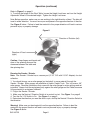
20 INCH DISC
SANDER / GRINDER
Model 45725
ASSEMBLY and OPERATING
INSTRUCTIONS
®
3491 Mission Oaks Blvd., Camarillo, CA 93011
Visit our Web site at http://www.harborfreight.com
Copyright © 2001 by Harbor Freight Tools®. All rights reserved. No portion of
this manual or any artwork contained herein may be reproduced in any shape or
form without the express written consent of Harbor Freight Tools.
For technical questions and replacement parts, please call 1-800-444-3353
Specifications
Motor
Disc Size
Disc RPMs
Miter Slot Width
Overall Dimensions
Base Dimensions
Table Tilt Capacity
Vacuum Chute Diameter
220V/60Hz, 2 HP Single Phase,11 Amps
20 Inches
1720
3/4”
27-1/8” x 10-3/8”
22” x 22”
30 Degrees Up, 45 Degrees Down
2-1/2” O.D. with 2-3/16” Adapter
Save This Manual
You will need the manual for the safety warnings and precautions, assembly instructions,
operating and maintenance procedures, parts list and diagram. Keep your invoice with this
manual. Write the invoice number on the inside of the front cover. Keep the manual and
invoice in a safe and dry place for future reference.
Safety Warnings and Precautions
WARNING: When using tool, basic safety precautions should always be followed to
reduce the risk of personal injury and damage to equipment.
Read all instructions before using this tool!
1.
Keep work area clean. Cluttered areas invite injuries.
2.
Observe work area conditions. Do not use machines or power tools in damp or wet
locations. Don’t expose to rain. Keep work area well lighted. Do not use electrically
powered tools in the presence of flammable gases or liquids.
3.
Keep children away. Children must never be allowed in the work area. Do not let
them handle machines, tools, or extension cords.
4.
Store idle equipment. When not in use, tools must be stored in a dry location to
inhibit rust. Always lock up tools and keep out of reach of children.
5.
Do not force tool. It will do the job better and more safely at the rate for which it was
intended. Do not use inappropriate attachments in an attempt to exceed the tool
capacity.
6.
Use the right tool for the job. Do not attempt to force a small tool or attachment to
do the work of a larger industrial tool. There are certain applications for which this tool
was designed. Do not modify this tool and do not use this tool for a purpose for which
it was not intended.
7.
Dress properly. Do not wear loose clothing or jewelry as they can be caught in
moving parts. Protective, electrically non-conductive clothes and non-skid footwear
are recommended when working. Wear restrictive hair covering to contain long hair.
SKU 45725
Page 2
07f
8.
Use eye, ear and face protection. Always wear ANSI approved impact safety
goggles. Wear a full face shield if you are producing metal filings or wood chips. Wear
an ANSI approved dust mask or respirator when working around metal, wood, and
chemical dusts and mists.
9.
Do not overreach. Keep proper footing and balance at all times. Do not reach over or
across running machines.
10. Maintain tools with care. Keep tools sharp and clean for better and safer
performance. Follow instructions for lubricating and changing accessories. Inspect tool
cords periodically and, if damaged, have them repaired by an authorized technician.
The handles must be kept clean, dry, and free from oil and grease at all times.
11. Disconnect power. Unplug tool when not in use.
12. Remove adjusting keys and wrenches. Check that keys and adjusting wrenches
are removed from the tool or machine work surface before plugging it in.
13. Avoid unintentional starting. Be sure the switch is in the Off position when not in
use and before plugging in.
14. Stay alert. Watch what you are doing, use common sense. Do not operate any tool
when you are tired.
15. Take caution as some woods contain preservatives such as copper chromium
arsenate (CCA) which can be toxic. When cutting these materials extra care should
be taken to avoid inhalation and minimize skin contact.
16. Check for damaged parts. Before using any tool, any part that appears damaged
should be carefully checked to determine that it will operate properly and perform its
intended function. Check for alignment and binding of moving parts; any broken parts
or mounting fixtures; and any other condition that may affect proper operation. Any
part that is damaged should be properly repaired or replaced by a qualified
technician. Do not use the tool if any switch does not turn On and Off properly.
17. Guard against electric shock. Prevent body contact with grounded surfaces such as
pipes, radiators, ranges, and refrigerator enclosures.
18. Replacement parts and accessories. When servicing, use only identical
replacement parts. Use of any other parts will void the warranty. Only use accessories
intended for use with this tool. Approved accessories are available from Harbor
Freight Tools.
19. Do not operate tool if under the influence of alcohol or drugs. Read warning
labels on prescriptions to determine if your judgment or reflexes are impaired while
taking drugs. If there is any doubt, do not operate the tool..
20. Maintenance. For your safety, maintenance should be performed regularly by a
qualified technician.
SKU 45725
Page 3
REV05/02
Note: Performance of this tool (if powered by line voltage) may vary depending on
variations in local line voltage. Extension cord usage may also affect tool performance.
Warning: The warnings, cautions, and instructions discussed in this instruction manual
cannot cover all possible conditions and situations that may occur. It must be understood by the operator that common sense and caution are factors which cannot be
built into this product, but must be supplied by the operator.
WARNING: Some dust created by power sanding, sawing, grinding, drilling, and other
construction activites, contain chemicals known [to the State of California] to cause
cancer, birth defects or other reproductive harm. some examples of these chemicals
are:
*
Lead from lead-based paints
*
Crystalline cilica from bricks and cement or other masonry products
*
Arsenic and chromium from chemically treated lumber
Your risk from these exposures varies, depending on how often you do this type of
work. To reduce your exposure to these chemicals: work in a well ventilated area, and
work with approved safety equipment, such as those dust masks that are specially
designed to filter out microscopic particles.
(California Health & Safety Code 25249.5, et seq. )
Note: This tool comes equipped with a 220 V power cord
with no plug. Have a plug installed by a licensed electrician.
This tool will only work on a 220 V outlet. If you need one
installed, use a licensed electrician.
Unpacking
When unpacking, check to make sure parts listed on page 8 are included. If any parts are
missing or broken, please call Harbor Freight Tools at the number on the cover of this
manual as soon as possible.
Warning! Operation of equipment in close proximity to a heart
pacemaker could cause interference or failure of the pacemaker.
Assembly
1. Have a licensed electrician attach a 220 Volt plug to the power cord.
2. Stick a PSA (Pressure Sensitive Adhesive) backed 20 inch sanding disc on the metal
sanding / grinding disc.
SKU 45725
Page 4
REV 05/02
Operation
Note: Prior to operation, go through the following checklist:
1. Make sure power is off before plugging in the Sander/ Grinder.
2. Check Sander / Grinder for damaged parts.
3. Make sure all clamps, locks, and bolts are tight.
4. Remove any adjusting keys or wrenches.
5. Make sure guards are in place and in proper working order.
Warning! Make sure table is securely locked into place following adjustments. Table should
be secured to a flat, level surface capable of supporting weight of the Sander/Grinder as well
as workpiece material being used.
6. Give Sander / Grinder a test run. If the tool vibrates irregularly or makes unfamiliar noises,
turn it off, unplug it, and refer to an authorized service technician.
Work Table Adjustment
Figure 1
On / Off Switch
Neutral / Direction Switch
Miter Slot
Height Adjustment Wheel
Work Table
Degree Gauge
Tilt Lock
Height Lock
Tilt Adjustment Wheel
Note: There must be a 1/16” clearance between the Work Table and the face of the Sanding
Disc. Refer to Figure 1 above.
1. The angle of the of the work table adjusts between 0 - 30 degrees to the left (standing at rear
adjustment), or 0 - 45 degrees to the right.
2. Loosen the Tilt Lock lever and turn the Tilt Adjustment Wheel to the desired direction. Use
the Degree Gauge to set precise angles. Tighten the Tilt Lock lever.
SKU 45725
Page 5
Operation (continued)
Refer to Figure 1 on page 5.
3. To adjust the height of the Work Table, loosen the Height Lock lever and turn the Height
Adjustment Wheel to the desired height. Tighten the Height Lock lever.
Note: Before operation, make sure you are working in the right direction of feed. The disc will
travel in either direction. You must move your workpiece in the opposite direction of the disc.
See Figure 2 below. Failure to feed the material in the proper direction will lead to serious
personal injury or property damage.
Figure 2
Direction of Rotation (left)
Direction of Feed
(right)
Caution: Keep fingers and hands well
clear of the spinning disc and the
clearance between the table and
the spinning disc.
Running the Sander / Grinder
Note: Your Sander / Grinder has a vacuum port (2-1/2” O.D. with 2-3/16” Adapter) for dust
collection.
1. You should always use a miter gauge (not included) to move material through the
Sander / Grinder. Miter gauges are available at Harbor Freight Tools. This tool uses a 3/4”
miter gauge. Read the instructions that come with the miter gauge for miter settings and adjustments. Always hold the workpiece firmly against the miter gauge and the Table; be aware
of the potential for workpiece “kickback”.
2. Plug in the Sander / Grinder.
3. Make sure the Neutral / Direction Switch is in neutral to start. See Figure 1 on page 5
4. Turn the On / Off Switch to On. See Figure 1 on page 5.
5. Determine the direction you want the disc to spin, and flip the Neutral / Direction Switch in
that direction.
Warning! Make sure you feed material from the opposite direction. Failure to feed the
material in the proper direction will lead to serious personal injury or property damage.
See Figure 2 above.
SKU 45725
Page 6
Operation (continued)
6. When you finish sanding or grinding, turn the Neutral / Direction Switch to neutral and wait
until the wheel comes to a complete stop. Turn off the On / Off Switch. See Figure 1.
7. If you wish to switch rotation direction without turning off the machine, turn the
Neutral / Direction Switch to neutral and wait until the wheel comes to a complete stop, and
then turn switch to the opposite direction.
Maintenance
Warning! Make sure your Sander / Grinder is unplugged before attempting any
maintenance.
1.
2.
3.
4.
5.
Remove your vacuum hose (not included) from the vacuum port and clean out port.
Clean the surface of the Sander / Grinder with a clean cloth or soft dry brush.
Check all nuts and bolts for tightness. Tighten if necessary.
Check sanding disk for tears or frays. Replace if necessary.
Clean debris from 3/4” miter slot.
SKU 45725
Page 7
Parts List
Part No.
1
2
3
4
5
6
7
8
9
10
11
12
13
14
15
16
17
18
19
20
21
22
23
24
25
26
27
28
29
30
31
32
33
34
35
Description
Base
Column
Cover/Support
Screw
Spring Washer
Set Washer
Motor Mount
Upper Spring Pin
Stud Bolt
Fixed Nut
Set Spring Washer
Fixed Washer
Spring Stud Bolt
Stud Washer
Bracket
Spring
Keeper
Sheave
Fixed Screw
Fixed Washer
Fixed Nut
Pin
Screw
Fixed Nut
Wire Rope
Screw Bracket
Handle
Handle Wheel
Set Screw
Shaft Base
Set Screw
Steel Washer
Shaft
Washer
Spring Pin
Qty.
1
1
1
4
4
4
1
1
1
1
1
1
1
1
1
2
2
2
1
2
1
1
1
1
1
1
1
1
1
1
4
4
1
2
1
Part No. Description
36
Spring Pin
37
Worm Gear
38
Washer
39
Fixed Washer
40
Sheave Stand
41
Lock Handle
42
Knob
43
Rack
44
Rack Set Screw
45
Solid Segment
46
Table
47
Screw
48
Fixed Pin
49
Table Adj.
50
Table Screw
51
Table Washer
52
Pilot
53
Pilot Screw
54
Spring Pin
55
Pilot
56
Gear Segment
57
Scale Set Knob
58
Scale Plate
59
Gear Segment
60
Worm Tilt
61
Spring Pin
62
Shaft
63
Screw
64
Pointer
65
Knob
66
Scale Set
67
Protractor
68
Nail
69
Set Screw
70
Set Nut
Qty.
1
1
1
1
1
1
1
1
2
1
1
1
1
1
1
1
1
4
1
1
1
1
1
1
1
1
1
1
1
1
1
1
3
1
1
Part No. Description
71
Set Screw
72
Fixed Washer
73
Motor Base
74
Washer
75
Fixed Nut
76
Fixed Screw
77
Steel Washer
78
Motor
79
Nut
80
Cord
81
Equal Key
82
Screw
83
Fixed Washer
84
Hub
85
Disc
86
Clamp Block
87
Clamp Screw
88
Sanding Cloth
89
Disc Guard
90
Left Arm Guard
91
Right Arm Guard
92
Guard Screw
93
Guard Washer
94
Guard Bracket
95
Screw
96
Washer
97
Set Screw
98
Set Washer
99
Set Nut
100
Adj. Screw
101
Switch Plate
102
Screw
103
Switch Control
104
Screw
105
Steel Washer
PLEASE READ THE FOLLOWING CAREFULLY
THE MANUFACTURER AND/OR DISTRIBUTOR HAS PROVIDED THE PARTS DIAGRAM IN THIS
MANUAL AS A REFERENCE TOOL ONLY. NEITHER THE MANUFACTURER NOR DISTRIBUTOR MAKES ANY REPRESENTATION OR WARRANTY OF ANY KIND TO THE BUYER THAT HE
OR SHE IS QUALIFIED TO MAKE ANY REPAIRS TO THE PRODUCT OR THAT HE OR SHE IS
QUALIFIED TO REPLACE ANY PARTS OF THE PRODUCT. IN FACT, THE MANUFACTURER
AND/OR DISTRIBUTOR EXPRESSLY STATES THAT ALL REPAIRS AND PARTS REPLACEMENTS
SHOULD BE UNDERTAKEN BY CERTIFIED AND LICENSED TECHNICIANS AND NOT BY THE
BUYER. THE BUYER ASSUMES ALL RISK AND LIABILITY ARISING OUT OF HIS OR HER
REPAIRS TO THE ORIGINAL PRODUCT OR REPLACEMENT PARTS THERETO, OR ARISING
OUT OF HIS OR HER INSTALLATION OF REPLACEMENT PARTS THERETO.
NOTE: Some parts are listed and shown for illustration purposes only and are not available
individually as replacement parts.
SKU 45725
Page 8
Qty.
4
8
2
4
4
4
8
1
4
1
1
3
3
1
1
1
1
1
1
1
1
4
4
2
2
2
2
2
2
2
1
2
1
4
4
Assembly Drawing
SKU 45725
Page 9