1
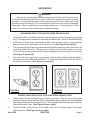
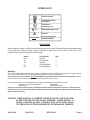
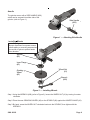
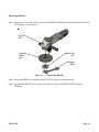
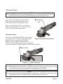
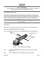
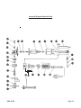
4” ANGLE GRINDER
42203
ASSEMBLY & OPERATING INSTRUCTIONS
3491 Mission Oaks Blvd., Camarillo, CA 93011
Visit our Web site at http://www.harborfreight.com
Copyright© 1999 by Harbor Freight Tools®. All rights reserved. No portion
of this manual or any artwork contained herein may be reproduced in any shape or
form without the express written consent of Harbor Freight Tools.
For technical questions and replacement parts, please call 1-800-444-3353
THANK YOU for choosing a HARBOR FREIGHT TOOLS product. For future reference, please complete the owner’s
record below:
Model_____________
Serial No.__________
Purchase Date___________
SAVE THE RECEIPT, WARRANTY AND THESE INSTRUCTIONS. It is important that you read the entire manual to
become familiar with the unit BEFORE you begin assembly.
Technical Specifications
Tool Name:
SKU:
Motor:
Cord Length:
Spindle:
Grinding Wheel:
4” Angle Grinder
42203
120V/ 60Hz, Single Phase, 11,000 RPM
8 FT. 2 Prong UL Approved
5/8” X 11 TPI with 7/8” Arbor
4” X 1/4” X 7/8”
E194601
GENERAL SAFETY RULES
WARNING!
READ AND UNDERSTAND ALL INSTRUCTIONS
Failure to follow all instructions listed below may result in
electric shock, fire, and/or serious injury.
SAVE THESE INSTRUCTIONS
WORK AREA
1.
Keep your work area clean and well lit. Cluttered benches and dark areas invite accidents.
2.
Do not operate power tools in explosive atmospheres, such as in the presence of
flammable liquids, gases, or dust. Power tools create sparks which may ignite the dust
or fumes.
3.
Keep bystanders, children, and visitors away while operating a power tool. Distractions
can cause you to lose control. Protect others in the work area from debris such as chips
and sparks. Provide barriers or shields as needed.
ELECTRICAL SAFETY
4.
5.
Grounded tools must be plugged into an outlet properly installed and grounded in
accordance with all codes and ordinances. Never remove the grounding prong or
modify the plug in any way. Do not use any adapter plugs. Check with a qualified
electrician if you are in doubt as to whether the outlet is properly grounded. If the
tools should electrically malfunction or break down, grounding provides a low resistance
path to carry electricity away from the user.
Double insulated tools are equipped with a polarized plug (one blade is wider than
the other). This plug will fit in a polarized outlet only one way. If the plug does not fit
fully in the outlet, reverse the plug. If it still does not fit, contact a qualified electrician
to install a polarized outlet. Do not change the plug in any way. Double insulation
eliminates the need for the three wire grounded power cord and grounded power supply
system.
SKU 42203
Page 2
REV 01/04
6.
Avoid body contact with grounded surfaces such as pipes, radiators, ranges, and
refrigerators. There is an increased risk of electric shock if your body is grounded.
7.
Do not expose power tools to rain or wet conditions. Water entering a power tool will
increase the risk of electric shock.
8.
Do not abuse the Power Cord. Never use the Power Cord to carry the tools or pull
the Plug from an outlet. Keep the Power Cord away from heat, oil, sharp edges, or
moving parts. Replace damaged Power Cords immediately. Damaged Power Cords
increase the risk of electric shock.
9.
When operating a power tool outside, use an outdoor extension cord marked “W-A”
or “W”. These extension cords are rated for outdoor use, and reduce the risk of electric
shock.
PERSONAL SAFETY
10.
Stay alert. Watch what you are doing, and use common sense when operating a
power tool. Do not use a power tool while tired or under the influence of drugs,
alcohol, or medication. A moment of inattention while operating power tools may result
in serious personal injury.
11.
Dress properly. Do not wear loose clothing or jewelry. Contain long hair. Keep your
hair, clothing, and gloves away from moving parts. Loose clothes, jewelry, or long hair
can be caught in moving parts.
12.
Avoid accidental starting. Be sure the Power Switch is off before plugging in. Carrying
power tools with your finger on the Power Switch, or plugging in power tools with the Power
Switch on, invites accidents.
13.
Remove adjusting keys or wrenches before turning the power tool on. A wrench or a
key that is left attached to a rotating part of the power tool may result in personal injury.
14.
Do not overreach. Keep proper footing and balance at all times. Proper footing and
balance enables better control of the power tool in unexpected situations.
15.
Use safety equipment. Always wear eye protection. Dust mask, nonskid safety shoes,
hard hat, or hearing protection must be used for appropriate conditions.
TOOL USE AND CARE
16.
Use clamps (not included) or other practical ways to secure and support the workpiece
to a stable platform. Holding the work by hand or against your body is unstable and may
lead to loss of control.
17.
Do not force the tool. Use the correct tool for your application. The correct tool will do
the job better and safer at the rate for which it is designed.
18.
Do not use the power tool if the Power Switch does not turn it on or off. Any tool that
cannot be controlled with the Power Switch is dangerous and must be replaced.
19.
Disconnect the Power Cord Plug from the power source before making any
adjustments, changing accessories, or storing the tool. Such preventive safety
measures reduce the risk of starting the tool accidentally.
SKU 42203
REV 01/04
Page 3
20.
Store idle tools out of reach of children and other untrained persons. Tools are
dangerous in the hands of untrained users.
21.
Maintain tools with care. Keep cutting tools sharp and clean. Properly maintained
tools with a sharp cutting edge are less likely to bind and are easier to control. Do not use
a damaged tool. Tag damaged tools “Do not use” until repaired.
22.
Check for misalignment or binding of moving parts, breakage of parts, and any other
condition that may affect the tool’s operation. If damaged, have the tool serviced
before using. Many accidents are caused by poorly maintained tools.
23.
Use only accessories that are recommended by the manufacturer for your model.
Accessories that may be suitable for one tool may become hazardous when used on another
tool.
SERVICE
24.
Tool service must be performed only by qualified repair personnel. Service or
maintenance performed by unqualified personnel could result in a risk of injury.
25.
When servicing a tool, use only identical replacement parts. Follow instructions in
the “Maintenance” section of this manual. Use of unauthorized parts or failure to follow
maintenance instructions may create a risk of electric shock or injury.
SPECIFIC SAFETY RULES
1.
Always use proper guard with grinding wheel. A guard protects the operator from
broken wheel fragments.
2.
Hold tool by insulated gripping surfaces when performing an operation where the
cutting tool may contact hidden wiring or its own cord. Contact with a “live” wire will
make exposed metal parts of the tool “live” and shock the operator.
3.
Maintain labels and nameplates on the Grinder. These carry important information.
If unreadable or missing, contact Harbor Freight Tools for a replacement.
4.
Always wear safety impact eye goggles and heavy work gloves when using this tool.
Using personal safety devices reduce the risk for injury. Safety impact eye goggles and
heavy work gloves are available from Harbor Freight Tools.
5.
Maintain a safe working environment. Keep the work area well lit. Make sure there is
adequate surrounding workspace. Always keep the work area free of obstructions, grease,
oil, trash, and other debris. Do not use a power tool in areas near flammable chemicals,
dusts, and vapors. Do not use this product in a damp or wet location.
6.
WARNING! All accessories for this tool must be rated for at least 12,000 RPM.
Grinding Wheels and other accessories running over the rated 12,000 RPM speed can fly
apart and cause injury.
7.
When using a hand-held power tool, always maintain a firm grip on the tool with both
hands to resist starting torque.
SKU 42203
Page 4
REV 01/04
8.
Use only 4” diameter Grinding Wheels (not included) having a 5/8” center mounting
hole. Never disable or modify the Wheel Guard.
9.
Avoid unintentional starting. Make sure you are prepared to begin work before turning
on this tool.
10.
Do not force this tool. This tool will do the work better and safer at the speed and capacity
for which it was designed. Do not force the rotating Grinding Wheel (not included) into the
object being ground. Apply moderate pressure, allowing the Grinding Wheel to rotate freely
without being forced.
11.
WARNING! Never install a carbide tipped or steel circular saw blade for use on
this tool. Never install a wood carving blade, carving disc with saw chain cutters, or
a cutting carving disc on this tool.
12.
For safest operation, it is recommended that only these accessories be used with
this tool: Abrasive Cut-Off Discs and Wheels, Flap Wheels, Wire Brushes, Wire Wheel
Brushes.
13.
Never lay this tool down until the Rotating Grinding Wheel has come to a complete
stop. The Rotating Pad can grab the surface and pull the tool out of your control.
14.
Never leave this tool unattended when it is plugged into an electrical outlet. Turn off
the tool, and unplug it from its electrical outlet before leaving.
15.
Always unplug this tool from its electrical outlet before performing inspection,
maintenance, or cleaning procedures.
16.
WARNING! Some dust created by power sanding, sawing, grinding, drilling, and other
construction activities, contain chemicals known (to the State of California) to cause cancer,
birth defects or other reproductive harm. Some examples of these chemicals are: lead
from lead-based paints, crystalline silica from bricks and cement or other masonry products,
arsenic and chromium from chemically treated lumber. Your risk from these exposures
varies, depending on how often you do this type of work. To reduce your exposure to these
chemicals: work in a well ventilated area, and work with approved safety equipment, such
as those dust masks that are specially designed to filter out microscopic particles.
(California Health & Safety Code 25249.5, et seq.)
17.
WARNING! People with pacemakers should consult their physician(s) before using
this product. Operation of electrical equipment in close proximity to a heart pacemaker
could cause interference or failure of the pacemaker.
Warning: The warnings, cautions and instructions discussed in this instruction manual
cannot cover all possible conditions and situations that may occur. It must
be understood by the operator that COMMON SENSE AND CAUTION ARE
FACTORS WHICH CANNOT BE BUILT INTO THIS PRODUCT, BUT MUST
BE SUPPLIED BY THE OPERATOR.
SKU 42203
REV 01/04
Page 5
GROUNDING
WARNING!
Improperly connecting the grounding wire can result in the risk of electric shock.
Check with a qualified electrician if you are in doubt as to whether the outlet is properly
grounded. Do not modify the power cord plug provided with the tool. Never remove the
grounding prong from the plug. Do not use the tool if the power cord or plug is damaged.
If damaged, have it repaired by a service facility before use. If the plug will not fit the
outlet, have a proper outlet installed by a qualified electrician.
GROUNDED TOOLS: TOOLS WITH THREE PRONG PLUGS
1.
Tools marked with “Grounding Required” have a three wire cord and three prong grounding
plug. The plug must be connected to a properly grounded outlet. If the tool should electrically
malfunction or break down, grounding provides a low resistance path to carry electricity
away from the user, reducing the risk of electric shock. (See Figure A, below left.)
2.
The grounding prong in the plug is connected through the green wire inside the cord to the
grounding system in the tool. The green wire in the cord must be the only wire connected
to the tool’s grounding system and must never be attached to an electrically “live” terminal.
(See Figure A, below left.)
3.
Your tool must be plugged into an appropriate outlet, properly installed and grounded in
accordance with all codes and ordinances. The plug and outlet should look like those in
the following illustration. (See Figure A, below left.)
FIGURE A
4.
5.
FIGURE B
DOUBLE INSULATED TOOLS: TOOLS WITH TWO PRONG PLUGS
Tools marked “Double Insulated” do not require grounding. They have a special double
insulation system which satisfies OSHA requirements and complies with the applicable
standards of Underwriters Laboratories, Inc., the Canadian Standard Association, and the
National Electrical Code. (See Figure B, above right.)
Double insulated tools may be used in either of the 120 volt outlets shown in the upper
right illustration. (See Figure B, above right.)
SKU 42203
Page 6
REV 01/04
EXTENSION CORDS
1.
Grounded tools require a three wire extension cord.
2.
As the distance from the supply outlet increases, you must use a heavier gauge
extension cord. Using extension cords with inadequately sized wire causes a serious
drop in voltage, resulting in loss of power and possible tool damage. (See Figure C.)
3.
The smaller the gauge number of the wire, the greater the capacity of the cord. For
example, a 14 gauge cord can carry a higher current than a 16 gauge cord. (See Figure C.)
4.
If using more than one extension cord to make up the total length, make sure each
cord contains at least the minimum wire size required. (See Figure C.)
5.
If you are using one extension cord for more than one tool, add the nameplate
amperes and use the sum to determine the required minimum cord size. (See Figure
C.)
6.
If you are using an extension cord outdoors, make sure it is marked with the suffix
“W-A” (“W” in Canada) to indicate it is acceptable for outdoor use.
7.
Make sure your extension cord is properly wired and in good electrical condition.
Always replace a damaged extension cord or have it repaired by a qualified electrician
before using it.
8.
Protect your extension cords from sharp objects, excessive heat, and damp or wet
areas.
REQUIRED MINIMUM EXTENSION CORD GAUGE - 110 VOLT
NAMEPLATE
AMPERES
(At Full Load)
6
8
10
12
14
16
18
20
22
24
26
28
30
EXTENSION CORD LENGTH
0-25 FT.
18
16
16
16
14
14
14
12
12
12
10
10
10
25-50 FT.
16
16
14
14
12
12
12
12
10
10
10
10
10
50-100 FT.
14
12
12
10
10
10
8
8
8
8
8
6
6
100-150 FT.
12
10
10
8
8
8
8
6
6
6
6
4
4
FIGURE C
SKU 42203
REV 01/04
Page 7
SYMBOLOGY
Double Insulated
Canadian Standards
Association
Underwriters
Laboratories, Inc.
V~
A
no xxxx/min.
Volts Alternating Current
Amperes
No Load Revolutions
per Minute (RPM)
UNPACKING
When unpacking, check to make sure the following parts are included. All sizes listed below are approximate.
If any parts are missing or broken, please call Harbor Freight Tools at the number on the cover of this
manual. Refer to parts diagram at end of manual.
Item #
N/A
29
28
2
N/A
Description
Grinder
Side Handle
Wrench
Grinding Wheel
Spare Brushes
Qty.
1
1
1
1
2
Warning:
There are certain applications for which this tool was designed. Harbor Freight Tools strongly recommends that this
tool not be modified and/or used for any application other than which it was designed.
All accessories must be rated for at least the RPM speed recommended on the tool’s warning label. Wheels
and other accessories running over rated speed can fly apart and cause injury.
For safest operation, it is recommended that only these accessories be used with this product:
Abrasive Cut-Off Discs and Wheels
Flap Wheels
Wire Brushes
Wire Wheel Brushes
Always use an approved and proper guard when using the above mentioned accessories. Each accessory
must have the correct arbor size and must fit properly on the shoulder bushing. Make sure accessories are
tightened down securely.
CAUTION: NEVER INSTALL A CARBIDE TIPPED OR STEEL CIRCULAR SAW
BLADE FOR USE ON THIS ANGLE GRINDER. NEVER INSTALL A
WOOD CARVING BLADE, CARVING DISC WITH SAW CHAIN
CUTTERS, OR A CUTTING CARVING DISC ON THIS ANGLE GRINDER.
SKU 42203
Rev 03/01
REV 01/04
Page 8
Handle
The grinder comes with a SIDE HANDLE (#29)
which can be screwed into either side of the
grinder. (refer to Figure 1.)
Side Handle
(#29)
Figure 1 — Attaching Side Handle
Installing Wheels
Warning:
Always disconnect from power source
before adding or removing accessories.
Use a cloth or glove to protect hands
from abrasion.
Spindle
(#5)
Inner Flange
(#3)
Wheel Nut
(#1)
Grinding
Wheel
(#2)
Wrench
(#28)
Figure 2 — Installing Wheels
Step 1: Using the WRENCH (#28) (refer to Figure 2), loosen the WHEEL NUT (#1) by turning it counter
clockwise.
Step 2:Place the new GRINDING WHEEL (#2) on the SPINDLE (#5) against the INNER FLANGE (#3).
Step 3: By hand, screw the WHEEL NUT clockwise back onto the SPINDLE, then tighten with the
WRENCH.
SKU 42203
Page 9
Removing Wheels
Step 1: Depress the LOCK PIN (#12) and turn the GRINDING WHEEL counterclockwise until the LOCK
PIN engages. (See Figure 3).
Lock Pin
(#12)
Wheel Nut
(#1)
Grinding
Wheel
(#2)
Wrench
(#28)
Figure 3 — Removing Wheels
Step 2: Using the WRENCH, loosen the WHEEL NUT by turning it counterclockwise.
Step 3:Unscrew the WHEEL NUT and remove, then remove the GRINDING WHEEL from the
SPINDLE
SKU 42203
Page 10
Starting the Grinder
WARNING:
Ensure the GRINDER is not locked ON before plugging it in. Check the SLIDE SWITCH (#19)
and make sure it is in the OFF position before plugging it into the power source.
Step 1: To turn the Grinder ON, push the Slide
Switch (#19) forward with your thumb to the
front position and the Grinder begins running.
Slide Switch]
(#19)
Step 2: To turn the Grinder OFF, move the Slide
Switch (#19) backward with your thumb to the rear
position until the Grinder stops running.
Using the Grinder
When using the GRINDING WHEEL, hold the grinder
Figure 4-Turning ON the Grinder
at an angle of 10° to 15° relative to the work surface.
When only the outer edge of the GRINDING
WHEEL is used, a rough cut surface will result.
If the disc is pressed flat against the work, the grinding
action will be irregular or bumpy and the tool will be difficult to control.
Work Surface
Figure 5 — Angle of Grinder
NOTE:
The HANDLE MUST BE USED AT ALL TIMES to maintain complete control of the tool. Place
it on either side where it will afford the best leverage and work visibility.
NOTE:
Motor may heat up with the prolonged medium to heavy use. To avoid motor burnout, do not
operate beyond a 15 to 20 minute duty cycle when using heavy force.
SKU 42203
Page 11
MAINTENANCE
WARNING:
DO NOT DISASSEMBLE.
This tool should be serviced by a qualified technician only. Incorrect reassembly can
result in electric shock, fire, or further damage to the tool.
Always keep the grinder clean
Dust and grit containing particles from metal grinding often accumulate on interior surfaces
and could create an electrical shock hazard if not frequently cleaned out. On a regular basis,
blow dust and grit out of the motor housing using compressed air. Never blow compressed air
at greater than 10 PSI. Always wear goggles and dust mask when using compressed air.
CAUTION:
Never use solvents or other harsh chemicals for cleaning the non-metallic parts of the tool. Use a
clean, dry rag only.
Carbon Brush
Replace the carbon brush when it wears down to about 3/16” (5 mm) or sparking will occur.
To change the CARBON BRUSH (#22) do the following:
Step 1: Using a flat tip screw driver, unscrew the BRUSH CAP (# 23) on the HOUSING (# 18).
Housing
(#18)
Carbon Brush (#22)
(#23)
Brush Cap
(#23)
Figure 6 — Replacing the Carbon Brushes
Step 2:
Replace the CARBON BRUSH with identical replacement parts from Harbor
Freight Tools.
Step 3:
Replace the BRUSH CAP on the HOUSING and screw-in to tighten.
SKU 42203
Page 12
PARTS LIST
Item #
Description
Qty
Item #
Description
Qty
1
Wheel Nut
1
16
Ball Bearing
1
2
Grinding Wheel
1
17
Stator
1
3
Inner Flange
1
18
Housing
1
4
Wheel Guard
1
19
Slide Switch
1
5
Spindle
1
20
Slide Bar
1
6
Packing Gland
1
21
Brush Holder
1
7
Ball Bearing
1
22
Carbon Brush
1
8
Gear
1
23
Brush Cap
1
9
Needle Roller Bearing
1
24
Cord
1
10
Gear Cover
1
25
Cover
1
11
Spring
1
26
Switch
1
12
Lock Pin
1
27
Switch Holder
1
13
Pinion
1
28
Wrench
1
14
Ball Bearing
1
29
Side Handle
1
15
Armature
1
SKU 42203
Page 13
Assembly Diagram-Exploded View
SKU 42203
Page 14