1
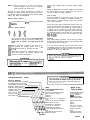
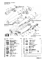
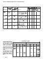
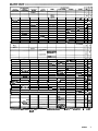
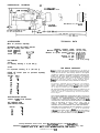
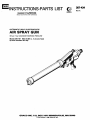
Parts
WARNING
Before cleaning the gun nozzle or attempting to service
the gun or other components, always turn off the high
voltage first, then shut down paint pump and trigger
gun to relieve fluid pressure.
Be sure your installation complies with all applicable
local codes.
ALWAYS use the lowest pressure possible when
flushing and use a grounded metal waste container.
Grounding
All components of the system, except the gun and paint
hoses, must be electrically grounded. Be sure the electric power circuit is properly grounded.
Be sure your gun is not grounded. Use un$rbunded
paint hoses to gun only, and be sure your supply pump
and the object you are painting are-grounded.
When flushing, avoid conductive solvents, if possible.
Be sure to turn off H.V. Power Supply before flushing,
and to remove all solvent from gun before turning on
high voltage.
r
Operating
Never use or store solvents in the spray area.
All conductive objects within 10 ft (3 m) of the gun must
be electrically grounded.
NEVER IMMERSE THE SPRAY GUN IN SOLVENT OR
OTHER LIQUID.
The object being coated must be grounded.
Keep work hangers and conveyor equipment clean so
work pieces are well grounded.
How The Elecnostatic
Automatic
Air Spray Gun Works
A transformer supplies high voltage current through the
cable to the gun’s ionizing electrode, where the electrostatic field is developed. The pump supplies paint
Be sure your installation complies with Federal, State
and local codes for the installation of electrical
apparatus in a Class 1, Divisions 1 and 2 Hazardous
Location.
The particular type and size system for your operation
will have to be custom designed for your needs. For a
correctly sized system, contact the Grace Finishing
System Division, Franklin Park, Illinois.
Mount the gun on an insulated stationary support or
reciprocator arm.
The spray gun has a mounting hole to fit a 0.5 in.
(13 mm) diameter rod. Use a mounting fixture which
allows adjustment of the spray pattern direction and
distance from the work.
through the hose and gun, where it is electrostatically
charged as it passes the ionizing electrode. The charged
paint is attracted to the grounded work piece, wrapping
around it and coating surfaces indirectly.
hose from the solenoid valve to the gun’s l/4” npt(m)
cylinder air inlet. Connect an air supply line to the
l/4” npt(m) atomizing air inlet.
BEFORE CONNECTING FLUID LINES, BLOW THEM
OUT WITH AIR AND FLUSH WITH SOLVENT. BE
SURE THAT THE SOLVENT YOU USE IS COMPATIBLE WITH THE MATERIAL TO BE SPRAYED.
Connect a fluid hose to the paint supply pump’s outlet
and to the gun’s 3/8 npsm fluid inlet.
Install fluid tip in gun. Be sure fluid pressure is relieved
and high voltage turned off before installing tip.
Recommended Hose Sizes (General Purpose)
MATERIAL
O-10 ft (O-3 m)
lo-35 ft (3-l 1 m)
35-100ft ill-30m)
100-200 ft (30-61 m)
I
l/4”
3/8”
l/2”
3/4”
ID
ID
ID
ID
I
l/4” ID
5/16” ID
3/4” ID
I
AIR
Install a normally closed, 3-way air solenoid valve in the
cylinder air supply line. BEFORE CONNECTING AIR
LINES BLOW THEM OUT TO REMOVE METAL CHIPS
AND OTHER FOREIGN PARTICLES. Connect an air
Adjust the system’s control device so the gun starts
spraying just before the spray meets the workpiece, and
stops as soon as it is past.
The gun requires a minimum of 30 psi (2 bar) air
pressure to the cylinder.
Fluid Control
Adjust the fluid flow to the proper rate, using a fluid
2
307434
I
O-50 ft (O-15 m)
50-100 ft (15-30 m)
100-200 ft (30-61 m)
regulator installed in paint line. It is best to adjust flow
rate with a fluid regulator.
Spray Pattern Control
Turn air adjusting screw (36) counterclockwise for a
wide flat spray pattern or clockwise to decrease to a
round pattern.
NOTE: When increasing to a wide, flat pattern,
increase supply of fluid to gun to maintain
same coverage over larger area.
Direction of
changed by
the desired
TIGHT. DO
spray pattern (horizontal or vertical) is
loosening lock ring and turning air cap to
position. TIGHTEN LOCK RING HAND
NOT OVERTIGHTEN.
Normal Spray Pattern
.: >: Proper adjustment will grve a spray pattern shaped
## Iike this.
$ $::i : .
0
Improper Spray Patterns
Heavy on top or bottom, right or left. Caused by
paint buildup on air cap or fluid tip, partially plug-
ged air holes or fluid tip. To remedy, clean the cap
or tip.
&$ Heavy in the center. Caused by too much, or too
@$ thick material. To remedy, reduce flow by re0
<is? ducing fluid pressure or thinning the paint.
Split pattern. Caused by insufficient paint, or too
much air pressure. To remedy, increase fluid
pressure or reduce air pressure.
Connect high voltage cable to the high voltage adapter
(44.
When all adjustments are made, -trigger air, atomizing
air, fluid pressure, and fan pattern,-you can turn on
the high voltage and begin operation.
Care of Gun
Good housekeeping is important. Clean the gun and
work area daily. A buildup of conductive residue on
either exterior or interior surfaces of gun may interfere
with proper operation.
Flush out the gun with an approved solvent at the end
of the work day. Wipe the outside of the gun with an
approved gun cleaner. Remove the air cap and clean it.
If ionizing wire of needle (41) is bent after cleaning,
straighten wire so that it is centered in fluid stream. For
an approved solvent or gun cleaner, see your local supplier or Grace Branch. Also, refer to OSHA 29 CFR
1910.107(g)(5).
Cleaning
After each spraying operation, turn off the high voltage
power supply, and solvent flush until all remaining paint
is removed from hose and gun.
If air cap needs cleaning, remove and soak in clean
compatible solvent (not over 15 minutes) and scrub with
a fine bristled brush. To clean out holes in air cap, use a
toothpick or other soft implement.
Never use metal instruments to clean holes in air
entire gun in
I WARNING I
Make sure the H.V. power supply electricity is
turned off before connecting or drsconnectrng the
high voltage leads at guns or junction arm.
TROUBLESHOOTING
CHART
WHAT’S WRONG
Fluid needle packing nut leakage
Air leakage from front of gun
Fluid leakage from front of gun
Spitting or fluttering spray
Defective spray pattern
“Orange Peel” finish
Streaks in finish
Runs or sags in f
Excessive spray
Fluid won’t corn
must be turned off. Before removing air cap or
spray tip, shut down paint pump and trigger gun
worn packing
Air valve not seating properly
Fluid needle not seating
properly
Fluid low
Loose fluid tip or damaged
seat
Loose air cap, dirty or damaged
fluid nozzle or air cap
Needle worn or damaged
Too much air pressure
Insufficient air pressure
Poorly mixed and/or strained
fluid
Fluid thinned out too much
Improper thinner
Clean,lubricate,service
Loosen packing nut,
clean or replace
Check fluid supply
Tighten,clean,replace
Tighten,clean,clear
replace
Replace
Use least necessary
Increase air pressure
Properly mix and
strain
Properly thin fluid
Use proper thinner
307434
3
should be taken when starting threads. Applied
vide you with years of durability and efficiency
These
working
parts
require
periodic
replacement:
1. Air cap (7).
2. Fluid tip (6).
3. Needle, fluid (41).
Removing Fluid Tip
To remove fluid tip (6) for cleaning or replacement,
remove the ring nut (8) and air cap (71, turn off the
atomizing air, trigger the gun to release needle pressure
on the tip. Remove the tip with a wrench. Replace with
the needle triggered to the rear.
When replacing air cap (7) on the gun, be sure the wire
electrode coming from the needle (41) is centered in the
air cap center hole. The best method is to slide the air
cap onto fluid housing (51, making sure that the wire
goes through center hole of air cap, then tighten ring
nut (8), onto barrel (42) allowing air cap to be drawn up
evenly on the fluid tip. Check alignment of ionizing wire
in the fluid stream.
Removing Fluid Tip Housing
If the housing (5) is removed, the o-rings (2) should be
replaced and the housing firmly seated. The housing
must be torqued no more than 15-20 ft-lb (20 N-m), or
plastic threads may become stripped. Lubricate with
petroleum jelly new o-rings on housing before replacing
in gun barrel.
NOTE:
Fluid tip (6) must be removed from housing
before replacing to avoid damage to ionizing
wire.
Replacing Fluid Needle
Turn off the atomizing air and fluid, trigger the gun to
release needle pressure on the tip. Remove ring nut (8)
and air cap (7). Remove fluid tip (6) with a 7/16 in.
wrench. Remove nut (19) and screw (31) from the rear
of the gun. With a long nose pliers pull out needle extension (46), nut (291, nut (301, spring (331, and needle
(41). Unscrew needle (41) from extension (46). (Pliers
maybe necessary as Loctite is used on threads.) Install
new needle (411, applying Locrite no. 290 or equivalent
to threads to prevent needle from coming loose during
operation. Reassemble needle into back of gun using
extreme care. Ionizing wire must remain straight as it
passes through rear actuator packings (18).
After needle is assembled in the gun, replace fluid tip (6)
and rear spring (33) and spring (341, along with adjusting screw (311, locknut (19) and air cap (7). For adjustment see Replacing Fluid Needle Extension.
4
307434
Replacing Needle Guide
Needle guide (47) is pressed into rear of fluid housing
(5). Remove fluid housing and press out needle guide.
When replacing be sure internal chamfered end faces
rear of fluid housing.
Replacing Fluid Needle Extension
Remove needle (see Replacing Fluid Needle). When
replacing extension (46); locknut (29) and needle adjusting nut (30) must be readjusted on needle extension.
Push needle (41), needle extension (46) and piston (38)
fully forward, and turn the adjusting nut (30) all the way
into the piston. Remove needle assembly from piston,
turn adjusting nut two turns counterclockwise, and
tighten locknut (29). This adjustment provides atom
izing air just before the fluid needle is engaged and after
seating.
Replacing Fluid Packing
The fluid packing (23) is replaced when the needle (41)
is removed. Remove the packing nut (22) then pick out
the packing and replace. Replace the packing nut. Insert the fluid needle, tighten the packing nut and apply
pressure on the packing to a firm seating. Do not overtighten. The fluid needle should move without binding.
When the gun is completely assembled and fluid
pressure applied, the packing nut may be tightened to
correct a slight leak.
Removing Gun Barrel
It is seldom necessary to remove the gun barrel (42)
from the gun body (37). When necessary, this is accomplished by unscrewing the gun coupling (8) and
carefully lifting away from the gun body. Inspect o-rings
(I and 4) and replace if necessary. To line up guide pin
in barrel with hole actuator assembly keep indicator detent intop of barrel lined up with top of actuator.
Replacing Cylinder Adapter
The cylinder adapter (43) should not be removed unless
damaged.
Replacing Electrode Stem of Fluid Needle
If electrode stem (48) of fluid needle (41) needs replacement, first unscrew electrode stem from fluid needle extension (46). Unscrew setscrew, and remove old electrode stem.
Insert new electrode stem and replace setscrew.
Reassemble fluid needle (41) to fluid needle extension
Ma
ELECTROSTATIC AUTOMATIC
AIR SPRAY GUN
Model 216-119
47
CHAMFERED END
TOWARD NEEDLE
Ref No. 39 Air Adjusting
Screw Assy includes items /
26-26 and 36.
HAND
TIGHT
(27-34 N-m)
Torque to
15-19 ft-lb
C20-25 N-m) I
REF
PART
NO.
103649
+103-823
722-615
+155-685
172-191
177-062
177-033
176-387
176-388
217-013
Series”B”
l
103338
l
103-523
“103-524
“103-610
“103649
“160-240
162-782
“174-099
171333
171332
“106901
169-870
176-773
105-456
*X8-1 10
170-242
170-243
L46
DESCRIPTION
PACKING, o-ring; viton
PACKING, o-ring; nitrile rubber
ELBOW, l/4 npt(m) x
x l/4 npsm(f) swivel
PACKING, o-ring; nitrile rubber
HOUSING, fluid tip
FLUID TIP, See chart for optional tips
AIR CAP, See chart for optional air caps
RETAINING RING
RETAINING RING
AUTOMATIC AIR VALVE ASSY.
includes items 1 l-40 and 52
PACKING, o-ring; viton
: GASKET; copper
. GASKET; copper
. PACKING, o-ring; viton
. PACKING, o-rina: viton
PACKING. v-blozk; leather
: LOCKNUi
. STUD, coupler
NUT, packing
: NUT, packing
PACKING, needle; PTFE
: ADAPTER, air inlet; l/4” npsm
HOUSING, spring
: WASHER
. O-RING, polyurethane
NUT, lock; needle
: NUT, needle adjusting
*Included in Repair Kit 215697.
(See back page).
PART
NO.
170-244
170-249
724391
170-253
171-722
217-198
21 O-743
“208-718
217-199
171-052
“215-695
214-919
724306
728-136
176390
176-513
215696
177-122
177-121
177-142
DESCRIPTION
. SCREW, needle adjusting
. CYLINDER, air piston
. SPRING, compression
. SPRING, compression
HOUSING, valve
: SCREW, air adjusting
. HOUSING, valve
PISTON, air
: AIR ADJUSTING SCREW ASSY.
includes items 26-28,36
(part of ref no. 10)
. GASKET, PTFE
(part of ref no. 10)
NEEDLE, fluid
BARREL
ADAPTER, cylinder
ADAPTER, 3/8-16 x 5/8 NPT
NEEDLE,
ext-fluid
GUIDE, needle
STEM, electrode (replacement kit of 25)
STEM, coupling
STEM, fluid
WRENCH
*Recommended “tool box” spare parts. Keep on hand to reduce
down time.
Order parts by name and number. Always give the model number and
series letter of the assembly for which you are ordering.
307434
5
AIR CAP CONSUMPTION AND FLUID TIP FLOW RATE CHART
5
Approximate
Pattern Length
Air Cap
254 mm (10 in)
Part Number
from gun
Air Consumption
ma/min @ 2.06 bar
(CFM e, 30 PSI)
.
/
177-666
177-d 177461 177463 Fluid Tip Part No
177532 355-710 591-1182 la351479
6-18
12-24
20-40
3550
1 mm
1.2 mm 1.5 mm 1.8 mm
fO.040 in) (0.047 in) (0.060 in) (0.070 in)
Description
177-033”
381-432 mm
(15-17 in)
0.266
(9.5,
Round end pattern, excellent atomization
for automatic and hand gun high production. Medium viscosity materials 19-30 sec.
No. 2 Zahn cup - metallics, lacquers and
enamels.
x
x
x
177-034
330361 mm
(13-15 in)
0.236
(8.5)
Round end pattern, very good atomization
for medium automatic hand gun production. Medium viscosity materials 19-30 sec.
No. 2 Zahn cup - primers, lacquers,
enamels, sealers
X
x
x
177-036
381432 m m
(15-17 in)
0.28
(10)
Tapered end pattern, excellent atomization
for heavy and high solid material. High
viscosity materials over 28 set No. 4 Zahn
cup - high solid lacquers, enamels, epoxies
and urethanes.
x
x
x
177-037
279-330 m m
(11-13 in)
Round end pattern, good atomization for
low production. Low viscosity materials
1522 set No. 2 Zahn cup - stains,
primers, sealers and lacquers.
177439
356-406 mm
(VI-16 in)
Tapered end pattern, very good atomization for heavy viscosity material over 28
set No. 4 Zahn cup - Water-Base and Frit
materials, acrylics, alkyds, vinyl, enamels
and lacquers.
x
x
X
FLOW Rate
ml/min
oz/min
,Fluid
Tip Size
X
‘Standard on Model 216-119.
The Equivalence Chart is
designed to update old style
guns with Fluid Tip and Air
Cap part numbers no longer
available, to current Fluid Tip
and Air Cap part numbers.
The left side of the chart
identifies old style guns with
the Fluid Tip and Air Cap part
numbers which are no longer
available.
The right side of the chart
gives the equivalent, current
Fluid Tip and Air Cap part
number that should be
ordered when replacing
parts.
6
307-434
EQUIVALENCE CHART
OLD GUN
NEW GUN
Part
Number
Fluid
Nozzle
Orifice
Size
Air
Cap
Part
Number
Fluid
Nozzle
Orifice
Size
Air
Cap
214-918
172-834
0.028
172-841
216-119
177-060
0.040
177-033
;; i-i;
172-835
0.040
177-062
0.047
172-836
0.060
177-061
0.060
177-063
0.070
172-842
172-318
171-630
177-034 177-037
177-033
177-034
177-036
177-037
177-033
177-034
177-036
177-039
177-036
m-p39
ACETONE .05 MEG.
0.6
TEXTILC
SPIRITS
1.06
BENZENE
1.2
TRICHLOAETHYLENE
ETHYL ACETATE
0.46 MEG.
I
I
METHVL
0. RES.
MEK
.05 MEG.
ALCOHOL
SC-1
soLvcSSodo
TOLUOL
1.NITRO
PROPANE
.-_-. . -----..--
r
METHYL AMYL
ACETATE
TURPENTINE
NONE
1A
29’
1.5
35
1.6
40’
2.5
a
2.7
41
3.0
do
3.6
55
11.6
99
11.6
120
I1 3
110
14
AMYL ALCOHOL
.06 MEG.
SC.106
SOLVESSO.lW
ETHYL CELLO.
-- .oll
_____^
SOLVt
MLlJ.
I
I
I
DIACETONE
.14 MEG.
I
DEPTINE
MINERAL
SPIRITS
I
I
I
BUTVL CELLOSOLVE
0.8 TO .19 MEG.
I
OOORLESS MIN.
ERAL SPIRITS
CVCLO HEXANOL
2.6 MEG.
SC.150
SOLVESSODOWANOL DPM
.03 MEG.
I
I
1
H N E OIL
<s
1.3
0.6 TO 36 MEG.
METHYL CELLO.
SOLVE .02 MEG.
I
o*
29
ETHYL ALCOHOL
D2 MEG.
SOPROPVL ALCOHOL
D 1. MEG
t
15
<
I
I
I
I
I
I
ISOPMORNE
.07 MEG.
I
I
I
I
910
19
116
21
107.
29
115
29
155
33
120.
3sl
104.
50
166
66.2
130.
72.5
154
96
152.
116
165
193
205
-1
176.
750
206.
,
SHELLY)J
EUTVL CARBITOL
RESISTANCE MEASURED WlTti
GRACO PROBE AND METER. LOW RESISTANCE,
OR POLAR. SOLVENTS MEASURE NORMALLY LESS THAN
HIGH RESISTANCE. OR NONPOLAR SOL VENTS MEASURE
S”AOE,,
AREASSHOW
HlGli RESISTANCE - N-BUTYL
ACETATE. AMYLAQTATE.
- - TAG CLOSED CUP
1 MEG
INFINITY.
307434
7
DIMENSIONAL
DRAWING
, *
,. . .
0.5” (13 mm) DIA
MOUNTING ROD HOLE
MAX WIDTH 1.31” (33.3 mm1
FLUID INLET
TECHNICAL DATA
ACCESSORIES
(Must be purchased separately)
STRAINER (AIR OR PAINT) 202-271
Uses the following filter screen:
157-332 (40 mesh)
156-967 (60 mesh)
cr -’
156-939 (100 mesh)
6
cd
cdl
v
Maximum operating voltage:
Maximum air & fluid working pressure:
Minimum air cylinder operating pressure:
Fluid inlet:
Atomizing air inlet:
Cylinder air inlet:
Weight:
100,000 volts
100 psi (7 bar)
30 psi (2 bar)
3/8 npsm(m)
l/4 npt(m)
l/4 npt(m)
3 lb. 2 oz. (1.4 kg)
H-V CABLES
724-410
For stationary mounting, 2 ft (610 mm) lg
727-997
For reciprocator mounting, 15 in. (381 mm) Ig
THE GRACO WARRANTY
REPAIR KIT 215-697 (must be purchased separately).
Consists of:
Ref No. Q;Y.
s
1
1
1
11
ii
15
16
This warranty is conditioned upon the prepaid return of the equipment
claimed to be defective for examination by Grace to verify the claimed
defect. If the claimed defect is verified, Grace will repair or replace
free of charge, any defective parts. The equipment will be returned to
the original purchaser transportation prepaid. If inspection of the
equipment does not disclose any defect in workmanship or material,
repairs will be made at a reasonable charge and return transportation
will be charged.
:
;
ii
28
38
Grace Inc. warrants all equipment manufactured by it and bearing its
name to be free from defects in material and workmanship under
normal use and service. This warranty extends to the original
purchaser for a period of 12 months from the date of purchase and
applies only when the equipment is installed and operated in
accordance with written factory recommendations. This warranty
does not cover damage or wear which, in the reasonable judgment of
Grace, arises from misuse, abrasion, corrosion, negligence, accident,
substitution of non-Grace parts, faulty installation or tampering.
:
1
ELECTRODE KIT 215-696
Consists of (25) 177-123 Electrode
KIT, REPAIR, GUN
(FAN VALVE) 215-506
Ref No.
27
28
Qty.
si
:
:
THIS LIMITED WARRANTY IS EXCLUSIVE, AND IS IN LIEU OF
ANY OTHER WARRANTIES (EXPRESS OR IMPLIED) INCLUDING
WARRANTY OF MERCHANTABILITY OR WARRANTY OF
FITNESS FOR A PARTICULAR PURPOSE AND OF ANY NONCONTRACTUAL LIABILITIES INCLUDING PRODUCT LIABILITIES
BASED ON NEGLIGENCE OR STRICT LIABILITY. EVERY FORM OF
LIABILITY FOR DIRECT, SPECIAL OR CONSEQUENTIAL
DAMAGES OR LOSS IS EXPRESSLY EXCLUDED AND DENIED.
EQUIPMENT NOT COVERED BY GRACO WARRANTY. Accessories
or components of equipment sold by Grace that are not manufactured
by Grace (such as electric motors, switches, hose, etc.) are subject to
the warranty, if any, of their manufacturer. Grace will provide
purchaser with reasonable assistance in making such claims.
Factory Branches: Atlanta, Dallas, Detroit (Southfield), Los Angeles, West Caldwell
(N.J.1
Subsidiary and Affiliate Companies: Canada; England; Switzerland; France; Germany; Hong Kong; Japan
GRACO INC. P.O. BOX 1441 MINNEAPOLIS, MN 55440
PRINTED IN U.S.A. 307434 8-80