1
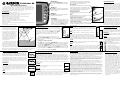
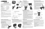
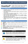
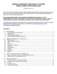
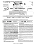
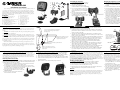
I
M
O
J
Fishfinder 80
K
Installation Instructions
A - Fishfinder 80 Sonar Unit (1)
B - Swivel Mount Bracket (1)
C - Swivel Base (1)
D - Mounting Knobs- Short (1), Long (1)
E - Mounting Knob Spacer (1)
F - Transducer With Power Cable (1)
G - Transducer Mount (1)
H - Trolling Motor Mount Gasket (1)
I - 5 mm Flat Washers (2)
K - 10-32 Lock Nut (1)
L - 4 x 12 mm Screws (4)
M - 10-32 x 1.75 Screw (1)
N - 1/4” Cable Clamps (2)
O - Plastic Spacer (1)
P - 1/4” Rubber Washer (1)
Q - Cable Tie, 5.6” (4)
R - Cable Tie, 20” (1)
S - Snap-Ring (1)
P
L
A
Q
E
S
B
G
DO NOT cut the transducer lead, this will void your warranty and may cause the
unit to not operate at optimal levels.
F
C
(Cable not shown)
Mounting the Transducer On a Transom
Do not mount the transducer behind strakes,
rivet lines, struts, fittings, water intakes or
discharge ports.
DO NOT mount the transducer behind strakes, rivet lines, struts, fittings, water
intake, discharge ports, eroding paint, or anything that creates air bubbles or causes the
water to become turbulent. It is important that the transducer be as close to the center
line as possible in calm, non turbulent water for optimal performance. Avoid mounting
the transducer in locations where the boat may be supported during launching, hauling, trailering or storage.
Mount the transducer away from the path of the prop on single drive boats. On
twin drive boats, mount the transducer between the drives if possible. Do not mount
the transducer directly in the path of the prop. The transducer can cause cavitation that
may degrade the boat’s performance and damage the prop.
Unit Installation — Selecting a Proper Location
Choose a location that provides optimal viewing while operating the vessel and
allows easy access to the unit’s keypad. Select a mounting surface strong enough to support the weight of the unit and protect it from excessive vibration or shock. DO NOT
mount the bracket in a location where the unit will be exposed to extreme temperature conditions. When installing the mounting bracket, be sure to allow room for the
connection/routing of the power cable.
Mounting the Bracket Assembly
Tool List (not included) - Drill, Screwdriver (Phillips or Standard), three #8 pan head
machine bolts with matching nuts and washers and a 5/32” drill bit, OR three #8 pan
head self-tapping screws and a 1/16” drill bit
1. Using the swivel base as a template, mark the location of the three holes which
will be used to secure the bracket to the mounting surface.
2. If securing the base with machine bolts, drill three 5/32” holes at the locations
you marked. OR, If securing the base using self-tapping screws, drill 1/16” starter
holes at the locations you marked. Starter holes should
generally be no deeper than half the screw length.
3. Secure the swivel base with three bolts or screws. DO
NOT OVERTIGHTEN.
4. Place the rest of the mount over the swivel base
and secure with the short knob.
1. Slide the large Cable Tie through slot on the Transducer Mount with the ridges of
the band facing up until equal lengths extend on both sides of the mount. (Note: For
cold water or heavy timber/debris areas, a metal 4-5” worm gear clamp is recommended.)
2. Position the Mount Gasket on the curved top of the Mount.
3. Place the transducer assembly against the motor body of the trolling motor with the
front of the transducer pointed away from the trolling motor propeller.
4. Place the pointed end of Cable Tie through the fastener hole on the
opposite end and pull through (you will hear clicks) until snug.
5. Position the transducer so that is will be parallel with the
bottom when in use and make sure the Gasket is aligned
properly. Pull the Cable Tie end until tight. Excess may be
trimmed off if needed. Tighten the 10-32 locking nut until
it touches the mounting bracket and then tighten 1/4
turn more (do not overtighten).
6. Route the 30’ (9 m) transducer cable using the
supplied cable ties to secure the cable to the
motor shaft. If desired, the forward-facing
portion (except the Cable Tie pocket) of
the Transducer Mount may be filled with
sealant to avoid debris accumulation.
H
D
Selecting a Transom Mount Location
For your sonar to operate properly, the transducer has to be located in clean (nonturbulent) water. The transducer should be mounted as near the center of the boat as
possible.
Mounting the Transducer On a Trolling Motor
1. Insert the Rubber Washer and Plastic Spacer
in the transducer at the same time. DO NOT
lubricate the Rubber Washer.
2. Route the cable towards the back and
slide the transducer into the mounting bracket.
3. Place a 5 mm Flat Washer on the 10-32 x
1.75" screw and insert the screw through
the Mounting Bracket, Spacer and Rubber
Washer.
4. Place the remaining 5 mm Flat Washer on
the exposed end and install the 10-32
Lock Nut finger tight. The transducer will be
tightened further after installation on boat.
Apply marine sealant to all screw
threads to prevent water from
seeping into the transom.
Mount the transducer parallel with the
water line.
Make sure the transducer is below
water level when the boat is on plane
at high speed.
Installing the Unit On the Mounting Bracket
1. Align the slot on the back of the unit with the long mounting knob and slide in
place. It may be necessary to adjust the long knob to spread the bracket arms
apart. (Turn counter-clockwise to widen the bracket arms, clockwise to tighten.)
2. Adjust the unit angle and tighten the long mounting knob until snug.
3. Tilt the unit by loosening the long knob on the right side of the bracket assembly.
4. Rotate the entire bracket by twisting it left or right. (NOTE: You will hear clicks as
you turn the bracket.)
5. Tighten all knobs once the desired viewing angle is obtained.
Tool List (not included) - Drill, 3/8" Wrench or Socket, 5/32" and 1/8" Drill Bits,
Masking Tape, #2 Phillips Screw Driver, Marine Sealant
1. Position the transom mount at the selected location, making sure the transducer is
parallel with the water line. Mark the center locations of each hole on the transom
mount. (see figures to the right)
2. Using the 5/32" bit, drill the pilot holes approximately 1" (25 mm) deep at the
marked locations. To avoid drilling the holes too deep wrap a piece of tape around
the bit 1" from the point of the bit.
3. Apply Marine Sealant to the 5 x 30 mm screws. Attach the transducer to the transom
using the 5 x 30 mm screws. Adjust the transducer to extend beyond the bottom
of the transom approximately 1/8" (3 mm) on fiberglass hulls or 3/8" (10 mm) on
aluminum hulls. Adjust the transducer to be aligned parallel with the water.
5. Tighten the 10-32 locking nut until it touches the mounting bracket and then
tighten 1/4 turn more (do not overtighten).
6. Place the first cable clamp on the transducer cable approximately one third of the
distance between the transducer and the top of the transom. Mark the location.
Using a 1/8" bit, drill a pilot hole approximately 3/8" (10 mm) deep.
7. Attach the cable clamp using a 4 x 12 mm screw. Coat the screw with marine sealant before installation. Repeat steps 6 and 7 using the other cable clamp.
8. Route the transducer cable as needed to the sonar unit. DO NOT CUT THE CABLE.
Try to avoid routing the cable with electrical wires or other sources of electrical
interference.
Wiring Harness Installation
The Fishfinder 80 comes with a wiring harness that connects the unit to power and
the transducer with one easy-to-remove connection. If it is necessary to extend the power
wires, use 22 AWG wire. DO NOT cut the transducer cable. This will void your warranty.
If your boat has an electrical system, it may be possible to wire the unit directly to an
unused holder on your current fuse block. If you are using the boat’s fuse block, remove
the in-line fuse holder supplied with the unit. You may also wire the unit direct to the battery. CAUTION: The Fishfinder 80 input voltage is 10-18 volts DC. DO NOT exceed
this voltage as this may damage the unit and void the warranty.
Installing the Wiring Harness:
1.
2.
3.
4.
5.
Determine the polarity of the power source using a Test Light or Volt Meter.
Install the Red (+) wire on the Positive fuse holder or battery terminal.
Install the Black (-) wire on the Negative fuse holder or battery terminal.
Install a 2 amp fuse in the fuse holder (fuse block only).
Align the notches on the cable plug and back of the unit. Insert the cable into the
connector and turn the lock ring counter-clockwise unit it stops.
Unit Care
Cleaning - Clean the unit housing using a cloth lightly dampened with a mild detergent
solution and then wipe dry. Avoid chemical cleaners and solvents that may damage plastic components. Do not apply cleaner to electrical contacts on the back of the unit.
Storage - Do not store the unit where exposure to temperature extremes may occur, as
permanent damage may result.
Drill Pilot Holes Here
Level
Vertical
Please read through these instructions thoroughly before attempting installation. Make sure
you completely understand these instructions before you begin. When in doubt, seek professional assistance. Be sure the wiring harness will reach the unit and transducer location before
beginning installation. The Garmin Fishfinder 80 hardware allows for installation on either
the transom or trolling motor. Please check the packing list below. If you are missing any items,
please contact your Garmin dealer.
Packing List:
J - 5 x 30 mm Screws (2)
R
N
Assembling the Transducer
Align with transom
bottom. Transducer should
extend 1/8” below fiberglass hulls or 3/8” below
aluminum hulls.
f Transom
Bottom o
Keep Parallel With Water Line
OK
Testing the Transom Mount Installation
This test is to be performed after the unit installation. See unit operating instructions for additional use information. Since water is necessary to carry the sonar signal,
the Fishfinder 80 will not function properly with the transducer out of the water. When
you place your boat in the water CHECK FOR LEAKS around the screw holes that are
below the water line. DO NOT leave your boat in the water for an extended period of
time without checking for leaks.
1. Begin testing the installation at a slow speed. If the sonar appears to be working
properly gradually increase the boat’s speed observing the sonar’s operation. If the
sonar signal suddenly is lost or the bottom return is severely degraded, note the
speed at which this occurs.
2. Return the boat to the speed the signal was lost. Make moderate turns in both
directions and see if the signal improves.
3. If the signal strength improves while turning, adjust the transducer so that it
extends another 1/8" below the transom of the boat. It may take several adjustments to eliminate the degradation.
4. If the signal does not improve it may be necessary to move the transducer to a
different location.
ARROW KEYS
Fishfinder 80
The UP and DOWN ARROW keys are used to
select items on the Adjustment Bar and Setup
menu.
Operational Instructions
Thank you for choosing the Garmin Fishfinder 80. This product is designed for
easy operation and to provide years of reliable service. Please read through these instructions to get the most out of your new unit. If you encounter a problem please contact
our Product Support Department at 913-397-8200, Monday - Friday 8:00 a.m. to 5:00
p.m. CST or on the internet at www.garmin.com/support.
Specifications
Case: Fully Gasketed, high-impact plastic alloy
Display: 3.9”(9.9 cm) diagonal, 2.0”W x 3.3”H (5 x 8.4 cm), 64 x 128 pixels
Size: 4.7” W x 4.9” H x 2.43 D (11.9 x 12.4 x 6.1 cm); Weight: 15.5 oz.
Temperature Range: +5° to 158°F (-15C to 70C)
Waterproof: IEC 529, level IPX-7 (submerged to 1 meter for 30 minutes)
Internal memory backup to retain user settings
Input: 10 to 18 Vdc w/ high voltage protection
Usage: 3.5 watts maximum, Nominal: 12 Vdc @ 0.15 amps
Sonar Power Output: 100 watts (RMS), 800 watts (peak to peak)
Frequency: 200 kHz
Depth: 600 foot max depth (Depth capacity is dependent on water salinity, bottom type and other
ENTER Key
The ENTER key is used to activate/deactivate
Adjustment Bar and Setup Menu data fields for
review or changes.
ENTER
Dead Zone
The MENU key is used to activate/deactivate
Adjustment and Setup Menus.
MENU
POWER Key
The POWER Key is used to turn the unit on/off
and to activate the display backlight. Press and
hold to turn the unit on/off. Press briefly and
release to activate the backlight. To change the
backlight level, press the POWER key repeatedly to cycle between Off, Low and High.
water conditions.)
Specifications subject to change without notice.
the bottom level. Weaker secondary
returns provide the detailed data. This
fish is currently in a Dead Zone and is
not detected by the sonar. The fish is in
the coverage area of the transducer, but
remember the first strong return sets
the bottom level. The fish will never
be detected since the bottom level will
never be set below the fish. The fish
on the right side of the display (shown
in light grey) will be detected and
displayed when the transducer cone
passes over the fish.
MENU Key
‘Range’ is used to set the display depth range. The unit can
be set to automatically track the bottom or set to a user-specified
range. Available settings are: ‘Auto’ (default) and 15-600 ft.
To immediately change the current adjustment option,
press the UP or DOWN ARROW key. If you wish to review
the available settings before making a change, press the ENTER key to activate the
adjustment window.
To change a setting on the unit:
Setup Menu (cont.) — Simulator
Units
‘Units’ can be configured to display measurements in Feet (ft,
default), Meters (m) or Fathoms (fa). (If the ‘Depth Alarm’ is set when
‘Units’ are changed, the ‘Depth Alarm’ will be defaulted to ‘Off’)
Whiteline ‘OFF’
(Simulated display)
The Adjustment Bar allows direct access to the settings most
commonly changed while using the unit. These include the depth
Range, Gain, Zoom and the View settings. Current Adjustment Bar
settings may be viewed by pressing the MENU key. Press MENU
again to hide the window or to exit any window. The current
adjustment option will always display in the upper left of the
display.
Setup Menu (cont.) — Whiteline
signal and display a thicker bottom layer. A weaker (soft) bottom
return will display a thinner bottom layer. The selections are: ‘Off’ or
‘On’ (default).
Noise Reject
‘Noise Reject’ helps filter unwanted noise from the chart (especially when moving at faster speeds) and can be turned ‘OFF’ or set
to a fixed value from 1-100%. Remember when setting the ‘Noise
Reject’, the higher the noise rejection setting, the more likely the
unit will not show fish or structure. The selections are: 1-100%
(default 50%) or ‘Off’.
To understand what the unit is displaying, it is important to have a general knowledge of how the unit works and how it determines what to display. The unit operates by
transmitting sound waves toward the bottom of a lake, stream or seabed in a cone shaped
pattern. The area covered by the transmitted sound waves is determined by the cone
angle of the transducer and the water depth. Using
Garmin’s standard 20° transducer, the coverage is
approximately 1/3rd of the water depth. The coverage area at a 30 foot depth is approximately a 10
3'
1'
foot diameter circle.
Range
3. To close a setting or menu window, press MENU.
Whiteline ‘ON’
Understanding Sonar
Using the Adjustment Bar
It is important to understand that
the unit does not display a 3-D representation of the underwater environment. The unit can display multiple
things (such as a fish and a tree) at the
same time, but can not determine where the return originated only when it was received.
Remember that the Fishfinder displays a 2D picture of the underwater environment. The
fish and tree could be located anywhere in the coverage area at that slice of time.
‘Whiteline’ controls how the unit displays information about
the bottom type (hard or soft). With the Whiteline ‘OFF’, the
bottom return will display as solid black and contain no information on bottom hardness. With Whiteline ‘ON’, the bottom
return will become a black & white pattern and can be used to
determine bottom hardness. A hard bottom will return a stronger
The Fishfinder 80 is able to display a variety of useful
information about the underwater environment. Below
are a few things the unit will help you see.
Water Depth
The unit displays water depth and can provide a warning when a specific depth is encountered. The Depth
Scale is displayed from top to bottom along the right
side of the display. Messages and Alarm Icons are
displayed along the bottom.
Water Temperature
The unit will display the water temperature at the
transducer.
Fish
The unit displays fish as arches or fish symbols in 3 sizes
and can alert you when a fish is detected.
Thermocline and Structure
GARMIN’s See-Thru® technology can display more than
just the thermocline and structure, the unit displays fish
in and below the thermocline, trees, brush and deadfall.
Bottom Shape and Type
Garmin’s unique DCG® (Depth Control Gain) system
provides a clear graphic representation of the bottom
type and its shape.
1. Press MENU, then using the UP or DOWN ARROW key, move the selection arrow
to the desired option and press ENTER. Choose ‘Setup’ for the main Setup Menu.
2. Using the UP or DOWN ARROW key move the selection arrow to the desired
setting and press ENTER. (The selection arrow will wrap when you reach the end
of a menu and adjustment window. If holding the ARROW key down, release then
press.) Holding down on an ARROW key will rapidly advance the selection speed.
The Fishfinder 80 comes with a built-in simulator mode that will allow the user
to practice and learn the operation of the unit at home rather than on the water.
The unit will indicate that it is running the simulator mode by displaying a message
in the lower left of the display. While in the simulator mode, the unit will display a
random bottom scene and the Fishfinder 80 can be controlled (except Noise Reject
and Gain) just as if it were on the water. To exit the Simulator, turn the unit off. If no
keys are pressed for 2 minutes, the unit will automatically reset while in simulator
mode. If the unit does not detect a transducer attached, it will automatically start in
Simulator mode.
Contrast
‘Contrast’ of the display may need to be adjusted to compensate for
light levels or viewing angles.
Defaults
This option allows you to restore the factory default settings for the
unit.
Warning: This product, its packaging, and its components contain chemicals known to
the State of California to cause cancer, birth defects, or reproductive harm. This Notice is being
provided in accordance with California’s Proposition 65. If you have any questions or would like
additional information, please refer to our web site at www.garmin.com/prop65.
Gain
‘Gain’ allows the user to control the sensitivity of the unit’s
sonar receiver. This provides some flexibility in what is seen on
the display. To see more detail, increase the receiver sensitivity
by selecting a higher gain (+). If there is too much detail or if the
screen is cluttered, lowering the sensitivity (-) may increase the clarity of
the display. Available settings are: ‘NRML’ (Normal, default) and +5 to -5.
Zoom
‘Zoom’ is used to quickly select a display zoom scale. Available settings
are: ‘OFF’ (default), ‘2X’ and ‘4X’ zoom.
View
‘View’ is available only when a Zoom scale other than ‘OFF’ is selected.
This setting allows you to select a specific zoom area to view on the display
or allow the unit to automatically select a zoomed viewing area based on
the bottom. When adjusting this setting, the top and bottom numbers will
reflect the zoomed view depth range.
Limited Warranty
This Garmin product is warranted to be free from defects in materials or workmanship for one year from
the date of purchase. Within this period, Garmin will at its sole option, repair or replace any components
that fail in normal use. Such repairs or replacement will be made at no charge to the customer for parts or
labor, provided that the customer shall be responsible for any transportation cost. This warranty does not
cover failures due to abuse, misuse, accident or unauthorized alteration or repairs.
THE WARRANTIES AND REMEDIES CONTAINED HEREIN ARE EXCLUSIVE AND IN LIEU OF ALL
OTHER WARRANTIES EXPRESS OR IMPLIED OR STATUTORY, INCLUDING ANY LIABILITY ARISING
UNDER ANY WARRANTY OF MERCHANTABILITY OR FITNESS FOR A PARTICULAR PURPOSE,
STATUTORY OR OTHERWISE. THIS WARRANTY GIVES YOU SPECIFIC LEGAL RIGHTS, WHICH
MAY VARY FROM STATE TO STATE.
IN NO EVENT SHALL GARMIN BE LIABLE FOR ANY INCIDENTAL, SPECIAL, INDIRECT OR CONSEQUENTIAL DAMAGES, WHETHER RESULTING FROM THE USE, MISUSE, OR INABILITY TO USE
THIS PRODUCT OR FROM DEFECTS IN THE PRODUCT. Some states do not allow the exclusion of
incidental or consequential damages, so the above limitations may not apply to you.
Garmin retains the exclusive right to repair or replace the unit or software or offer a full refund of the
purchase price at its sole discretion. SUCH REMEDY SHALL BE YOUR SOLE AND EXCLUSIVE REMEDY
FOR ANY BREACH OF WARRANTY. Products sold through online auctions are not eligible for rebates or
other special offers from Garmin. Online auction confirmations are not accepted for warranty verification.
To obtain warranty service, an original or copy of the sales receipt from the original retailer is required.
Garmin will not replace missing components from any package purchased through an online auction.
To obtain warranty service, contact your local Garmin authorized dealer. Or call Garmin Customer
Service for shipping instructions and a RMA tracking number. The unit should be securely packed with
the tracking number clearly written on the outside of the package. The unit should then be sent, freight
charges prepaid, to any Garmin warranty service station. A copy of the original sales receipt is required as
the proof of purchase for warranty repairs.
The Fishfinder 80 has no user-serviceable parts and is fastened shut with screws. Any attempt to open
the case to change or modify the unit in any way will void your warranty and may result in permanent
damage to the equipment.
When a transmitted soundwave strikes an
underwater object, sound is reflected back to the
transducer. The transducer collects the reflected
sound waves and sends the data to the unit to be
processed and displayed on the chart. The underwater data is displayed on the chart in the order
that it is returned: first returned—first on the chart.
Generally speaking, if the only thing between the
transducer and the bottom is water, the first strong
return will come from the bottom directly below
the transducer. The first strong return sets (cont.)
2'
6'
3'
9'
4'
12'
5'
15'
6'
18'
7'
21'
8'
24'
9'
27'
10'
30'
Setup Menu — Depth Alarm
‘Depth Alarm’ can be set to sound a shallow water warning at a
depth determined by the user. (If the ‘Depth Alarm’ is set when ‘Units’
are changed, the ‘Depth Alarm’ will be defaulted to ‘Off’.) This alarm
may be set to ‘Off’ (default) or from 1-600 ft.
Fish Alarm
‘Fish Alarm’ can be configured to sound when the unit detects what it determines to
be a fish. The alarm selections are: ‘Off’ (default) or ‘On’.
Fish ID
‘Fish ID’ allows the user to determine how the chart will display underwater
targets and background information. If ‘Fish ID’ is set to ‘OFF’, the unit will display
all of the available information about the underwater environment. If a fish symbol
is selected, the chart will display only the information related to that symbol (large,
medium and small sizes).
— All available information will be displayed.
— Suspended targets displayed as symbols. No background information will be
displayed in this mode.
— Same as above with target depth displayed.
— Suspended targets will display as symbols. In this mode background
information will still be displayed making fish identification easier.
— Same as above with target depth displayed. (default)
Software License Agreement
By using the Fishfinder 80, you agree to be bound by the terms and conditions of the
following software license agreement. Please read this agreement carefully.
Garmin grants you a limited license to use the software embedded in this device (the
“Software”) in binary executable form in the normal operation of the product. Title, ownership rights and intellectual property rights in and to the Software remain in Garmin.
You acknowledge that the Software is the property of Garmin and is protected under
the United States of America copyright laws and international copyright treaties. You further
acknowledge that the structure, organization and code of the Software are valuable trade
secrets of Garmin and that the Software in source code form remains a valuable trade secret
of Garmin. You agree not to decompile, disassemble, modify, reverse assemble, reverse
engineer or reduce to human readable form the Software or any part thereof or create any
derivative works based on the Software. You agree not to export or re-export the Software to
any country in violation of the export control laws of the United States of America.
© Copyright 2002-2003 Garmin LTD. or its subsidiaries
GARMIN®, DCG® and See-Thru® are registered trademarks of Garmin Ltd. or its subsidiaries
and may not be used without the express permission of GARMIN.
Garmin International, Inc. 1200 East 151st Street, Olathe, Kansas 66062, U.S.A.
Tel.913/397.8200 Fax. 913/397.8282
Garmin (Europe) Ltd. Unit 5, The Quadrangle, Abbey Park Industrial Estate, Romsey, SO51
9DL, U.K. Tel. 44/1794.519944 Fax.44/1794.519222
Garmin Corporation No. 68, Jangshu 2nd Road, Shijr, Taipei County, Taiwan
Tel. 886/2.2642.9199 Fax. 886/2.2642.9099
www.garmin.com
Part Number 190-00301-00 Rev. B