1
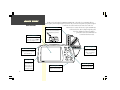
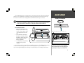
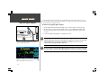
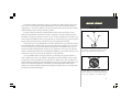
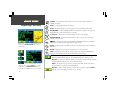
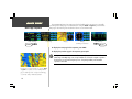
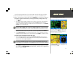
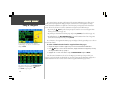
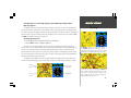
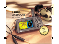
Q u i c k Sta rt
GPSMAP 295
Quick Start Guide
d
Rea
This !
t
Firs
1
Q u i c k Sta rt
Unit Features
Color LCD Display
Thank you for purchasing the GARMIN GPSMAP 295 —the result of our continuing effort to
provide quality, user-friendly navigation systems for all your needs. This Quick Start guide is designed
to introduce the basic functions of the unit. Please take a few
Detachable Antenna
moments now to review the features of your GPSMAP 295,
To remove, rotate to ten o’clock
as illustrated below. After reading through this guide,
position (when viewed from back)
if you have additional questions regarding a
and pull away from unit.
particular feature, more information can
be found in the Pilot’s Guide.
On-screen information is referred
to as a “page”. Press the PAGE
key to select a different screen.
GPSMAP
295
Power/Backlight Key
PAG
E
Power/Data Connector
MAR
ENT K
ER
QUIT
(Back Side / Top) Connections
for power, ground, serial data in
and serial data out.
OUT
IN
WPT
ROU
TE
Battery Door
(Back Side) To open,
turn metal D-ring
counterclockwise 1/4
turn and pull battery
door away from unit.
2
Press and hold to turn
on/off. Press momentarily
to adjust screen backlight
and contrast.
MEN
U
NRS
T
Rocker Keypad
Cartridge Door
(Bottom) For optional
MapSource™ data cartridge.
Moves the cursor, pans the
map page and enters data.
The GPSMAP 295 operates on 6 AA batteries or an external power source (from 10-35 volts DC).
AA batteries are installed in the compartment on the back of the unit. These batteries provide up to
three hours of continuous use. Rechargeable NiCad or lithium batteries may also be used.
1
Q u i c k Sta rt
Battery Installation
The on-screen battery level indicator is calibrated for alkaline batteries, and will not be
accurate when using NiCad or lithium batteries. A setting is provided for NiCad batteries.
See the Pilot’s Guide for instructions on setting the indicator to NiCad batteries.
To install the batteries:
1. Flip up the metal D-ring on the
battery cover, and turn the D-ring
1/4 turn counterclockwise. Lift the
cover away from the rear of the
unit.
2. Install the batteries and replace
the battery cover. When installing
the batteries, observe the polarity
markings engraved inside the
battery compartment.
Rotate the metal D-ring to remove the battery cover.
+
+
+
+
+
+
3. Lock the battery cover in place by
rotating the D-ring 1/4 turn
clockwise.
Battery life varies due to a variety of factors, including temperature and backlighting level. Lithium
AA batteries will provide longer life in colder ambient temperatures. For your convenience, all
user-created waypoints, flight plans and settings are retained while you’re changing the AA batteries.
Observe the polarity markings engraved in the battery
compartment for proper battery installation. Improper
battery installation may cause battery leakage and
personal injury or damage to your GPSMAP 295.
3
Q u i c k Sta rt
Cigarette Lighter Adapter
A cigarette lighter adapter is provided with your GPSMAP 295. For extended operation, you may
wish to use this adapter and leave the batteries installed as a backup power source. External power from
10 to 35 volts DC may be applied to the unit.
To connect the cigarette lighter adapter:
1. Lift the rubber weathercap from the power/data connector at the top rear of the unit (see left).
2. Observe the groove on the round 4-pin female connector on the cigarette lighter adapter. Align
the notch on the power/data connector with this groove and press the female connector firmly
into place.
3. Connect the cigarette lighter plug into a suitable power source.
.
Connect the cigarette lighter adapter to the power/data
connector on the top rear of the unit.
When using external power, the on-screen battery level
indicator is replaced by an external power icon.
4
1
A fuse is located under the threaded tip of the cigarette lighter plug. An indication on the
Satellite Status Page shows when external power is supplied to the unit (see bottom left).
If this indication does not appear, verify that the external power source is on and
connected, then check the condition of the fuse.
Be sure to route the cigarette lighter cable in a manner which does not interfere with vehicle
operation! Failure to route the cable AWAY FROM vehicle controls may result in an accident.
The Global Positioning System (GPS) consists of a network of 24 satellites which circle the earth
twice a day in a very precise orbit and transmit information back to Earth. The GPSMAP 295 must
continuously “see” at least three satellites to calculate your position and track your movement. At times,
additional satellites may be needed to determine a position.
By using an almanac (a timetable of satellite numbers and their orbits) stored in the receiver’s
memory, the GPSMAP 295 can determine the distance and position of any GPS satellite and use this
information to compute your position. Your GPS receiver can only see satellites above the horizon, so it
needs to know what satellites to look for at any given time. To use this almanac data, your GPS needs to
either be told its general location (be “initialized”) or given the opportunity to find itself.
The first time you use your GPSMAP 295, it may take several minutes to get a position fix. Because
the GPSMAP 295 relies on satellite signals to provide you with navigation guidance, the receiver needs
to have an unobstructed, clear view of the sky for best performance. In a nutshell, the GPS receiver’s
view of the sky will generally determine how fast you get a position fix—or if you get a fix at all. GPS
signals are relatively weak and do not travel through rocks, buildings, people, metal or heavy tree cover,
so remember to keep a clear view of the sky at all times for best performance.
Once the GPSMAP 295 has calculated a position fix, you’ll usually have anywhere from five to
twelve satellites in view. The receiver will then continuously select the best satellites in view to update
your position. If some of the satellites in view get blocked, or “shaded”, the receiver can simply use an
alternate satellite to maintain the position fix. Although a GPS receiver needs four satellites (or more) to
provide a three-dimensional (3D) fix, it can maintain a two-dimensional (2D) fix with only three
satellites. A three-dimensional fix includes latitude, longitude and altitude; whereas a two-dimensional
fix includes only latitude and longitude.
Q u i c k Sta rt
What is GPS?
GPSMAP
295
PAGE
MARK
ENTER
QUIT
OUT
IN
WPT
ROUTE
MENU
NRST
The GPS antenna’s view of the sky will determine how fast you
get a position fix, or if you obtain a fix at all. GPS signals do
not pass through obstructions made of wood or metal.
The 24 GPS satellites are constantly moving, orbiting the
earth twice a day. In order to calculate your position, the GPS
receiver needs to continuously “see” at least three satellites.
5
Q u i c k Sta rt
Keypad Usage / Data Entry
(POWER)— Press and hold to turn the unit on or off. Press momentarily to adjust screen
backlight and contrast.
(PAGE)— Scrolls through main pages in sequence.
PAG
E
QUIT
(QUIT)— Returns the display to a previous page or restores a data field’s previous value.
MAR
ENT K
ER
(ENTER/MARK)— Activates highlighted fields and confirms menu options or data entry. Press
and hold this key to mark present position as a waypoint.
IN
OUT
(IN and OUT)— Allows you to zoom in/out through 24 scales on the Map Page.
(ROCKER KEYPAD)— Controls the movement of the cursor, is used to select options and
positions, and to enter data.
Example of the on-screen cursor highlighting the “GOTO”
button. Use the ROCKER KEYPAD to move the cursor
around the page.
WPT
MEN
U
ROU
TE
NRS
T
( D WPT)— Allows you to retrieve Jeppesen database information and/or select a destination
waypoint. Press and hold this key to display favorite waypoints list.
(MENU)— Displays a menu of available options for the current page. Press twice to display the
Main Menu.
(ROUTE)— Displays a list of stored routes and allows you to create new routes.
(NRST)— Displays nine nearest airports, navaids, airspaces, user waypoints, ARTCC & FSS
frequencies, cities, highway exits and optional MetroGuide points of interest.
CURSOR— A highlighted area on the screen (black text on yellow) which can be moved up,
down, left and right with the keypad to select individual fields on the display (see left).
DEFAULT— A system-selected format, built into the operating software or the unit’s memory,
that will be followed unless the user chooses a different setting.
Example of the on-screen cursor during data entry. Data
entry begins and ends with the ENTER key. Use the UP/
DOWN portion of the ROCKER KEYPAD to select the
desired character and RIGHT to move to the next character.
6
FIELD— The location on a page (such as a “waypoint name field”, shown at left) where a
group of characters or option is entered and displayed.
BUTTON— Similar to “Field”. Place the on-screen cursor on a button and press ENTER to
select the action corresponding to that button (e.g., “GOTO”).
Take the GPSMAP 295 outside and find an open area where the antenna has a clear view of the sky.
You may either hold the unit at a comfortable height with the antenna pointing up (see page 2), or
place the unit in one of the supplied mounting brackets (see Appendix A in your Pilot’s Guide).
Q u i c k Sta rt
Turning On & Off
To turn the GPSMAP 295 on, press and hold the RED POWER KEY.
A Welcome Page will appear while the unit conducts a self test. Once testing is complete, the
Welcome Page is replaced by a Database Page (which shows the effective date for the Jeppesen database
and a warning that the GPSMAP 295 is for VFR use only).
Press ENTER to acknowledge the Database Page.
During normal use, expect a position fix in 30-45 seconds. You’ll know you have a position fix
when the unit automatically transitions from the Satellite Status Page to the Map Page. Your GPSMAP
295 is now ready to use!
To turn the unit off, press and hold the RED POWER KEY for one second.
Backlighting and Contrast Adjustments
From any page you can quickly adjust the screen backlighting and contrast using the RED POWER
KEY. Press this key momentarily to display a window, with sliding scale adjustments for both backlighting and contrast. The ROCKER KEYPAD controls adjustments while the window is being displayed.
After the initial Welcome Page, the Database Page appears to
indicate the database coverage area and effective dates. A
warning also reminds you that electronic charts should always
be double-checked for accuracy and are for VFR use only.
To adjust screen backlighting and contrast:
1. From any page, press the RED POWER KEY to display a screen settings window.
2. Use the UP/DOWN portion of the ROCKER KEYPAD to change the backlighting settings. UP will
increase backlight intensity.
3. Use the LEFT/RIGHT portion of the ROCKER KEYPAD to adjust screen contrast. LEFT will make
screen contrast lighter.
4. Press ENTER to accept any changes and remove the screen settings window. Alternatively, if no
keys are pressed, the screen settings window will automatically be removed after five seconds.
Once a position fix is determined, the GPSMAP 295 will
automatically transition to the Map Page (provided no keys
have been pressed after turning the unit on).
7
Q u i c k Sta rt
Satellite Status Page
The signal strength bars give you an indication of what
satellites are visible, whether they’re being used to calculate
a position fix, and the signal quality. Solid bars indicate
satellite(s) ready to be used to determine a position fix.
The Satellite Status Page is the first main page you’ll view while your GPSMAP 295 is acquiring
satellites and determining a position. This page shows you status information including number of
satellites received, their location above you in the sky, and the signal strength of each satellite received.
And, it’s the page that you’ll want to occasionally refer back to for condition of the AA batteries (when
using battery power).
The “sky view” portion of the page shows the location of overhead satellites. The outer ring
represents the horizon in all directions from your current location—and includes cardinal headings for
reference. The inner ring represents an elevation (angle above the horizon) of 45°. Satellites appearing
at the center of the “sky view” are directly overhead.
To the right of the “sky view” are signal strength bars. These bars give an indication of what
satellites are currently being received, the signal quality, and whether or not they’re being used to
calculate a position fix (solid or hollow bars). Satellites are indicated on the “sky view” and signal
strength bars by their corresponding number, from 01 through 32.
The top of the page indicates the status of your current position fix (e.g., Acquiring, 2D Navigation,
3D Navigation, etc.) and your estimated position error (EPE).
The bottom right corner of the page indicates battery level or connection to an external power
source (see page 4).
Receiver
Status
Position Error
(Accuracy)
Signal
Strength Bar
If satellite reception is lost, or an insufficient number of
satellites are available, you will be alerted with a ‘Poor
Coverage’ receiver status and message.
8
Sky View
Battery Level
Indicator
If some of the screen examples on the following pages do not generally match what you see on your
GPSMAP 295, your unit may be in “Land Mode”. Land Mode substitutes some aviation features with
equivalents more suitable for automotive use. Some alert messages, which would be appropriate in the
cockpit, are disabled to prevent nuisance messages not needed while driving.
Additionally, there are many settings on the GPSMAP 295 you can make on your own. For
example, speed can be displayed in knots, miles per hour or kilometers per hour. The GPSMAP 295
provides the flexibility to have separate settings for Aviation Mode and Land Mode (and saves them so
you do not have to re-enter them the next time you switch between modes).
The chart below describes the differences between Aviation and Land Mode.
Q u i c k Sta rt
Aviation vs. Land Mode
AVIATION MODE:
Uses Airplane Symbol on Map to indicate current position.
Airplane Symbol appears at GPS-determined position.
HSI Page is displayed for Navigation Guidance.
Press MENU, with the Satellite Status Page displayed, to
show the page options. ‘Enter Land Mode’ or ‘Enter Aviation
Mode’ will appear—allowing you to select the other mode.
GOTO navigation is along Selected Course (determined when GOTO is initiated).
Independent (from Land Mode) user-defined settings for Distance, Speed, North reference (true or magnetic),
Arrival Alarm, Land Data (appearing on Map), Aviation Data (appearing on Map).
LAND MODE:
Uses Pointer Symbol on Map to incidate current position.
Pointer Symbol is aligned to the Nearest Road (where practical).
RMI Page is displayed for Navigation Guidance.
GOTO navigation is from Present Position (updates guidance information as you drive).
All Vertical Navigation (VNAV) messages, All Airspace Alert messages and “Off Course Alarm” are disabled.
Independent (from Aviation Mode) user-defined settings for Distance, Speed, North reference (true or
magnetic), Arrival Alarm, Land Data (appearing on Map), Aviation Data (appearing on Map).
The RMI Page replaces the HSI Page when Land Mode is
selected. The RMI Page depicts direction of travel (ground
track) on a rotating compass card, and bearing to
destination using a bearing pointer.
9
Q u i c k Sta rt
The GPSMAP 295 features five main pages which are linked together, in series. You can quickly
cycle through these main pages—in either direction—using the PAGE and QUIT keys. Each of these
main pages is described in greater detail in the reference section of this manual.
Satellite Status Page
PAG E
>>>
Position Page
Map Page
HSI Page
(or RMI Page in Land Mode)
Active Route Page
>>>
Main Page Sequence
QUIT
To display the next page in the sequence, press PAGE.
.
To display the previous page in the sequence, press QUIT.
If you prefer to use a full screen map, you can use the PAGE
and QUIT keys to quickly cycle between the Map and HSI
pages. A smaller map can also be depicted on the HSI page.
See your Pilot’s Guide for additional information.
10
During normal use the GPSMAP 295 will automatically sequence from the Satellite
Status Page to the Map Page once enough satellites are received to compute a position
fix. If any keys are pressed during the process of acquiring satellites, this automatic
sequence is cancelled.
One of the most important features of your new GPSMAP 295 is the built-in Jeppesen database,
which inlcudes information on airports, runways, frequencies, approaches, navaids and airspace
boundaries. This information is readily available from the D WPT key or directly from the Map Page.
Q u i c k Sta rt
Viewing Database Info
To view the database information by entering the identifier, facility name or city:
1. Press D WPT.
2. The waypoint information pages will appear. A series of file tabs along the top of the page identify
each category of waypoint information: aviation (for airport/VOR/NDB/intersection locations),
runways, communication frequencies and approaches. Use the LEFT/RIGHT portion of the ROCKER
KEYPAD to select the desired file tab.
.
Airports, VORs and NDBs can be selected by identifier, facility name or city. Intersections
and user-created waypoints can only be selected by identifier (not facility name or city).
3. Highlight the identifier field (or facility name field or city field, if applicable) and press ENTER.
4. Use the ROCKER KEYPAD to enter the identifier (facility name or city)—UP/DOWN to change the
highlighted character and RIGHT to move to the next character. Press ENTER to confirm the selection.
You can retrieve database information for airports, VORs
and NDBs by pressing the D WPT key and entering the
identifier, facility name or city. Database information for
intersections is available only by identifier.
To view database information from the Map Page:
1. With the Map Page displayed (see page 10), use the ROCKER KEYPAD to place the panning
cursor over the desired facility on the map. When the cursor is directly over the desired item, the
identifier for that item will appear highlighted.
.
For airspace information, place the cursor over any open area within the boundary of the
desired airspace. The boundary line is then highlighted and airspace information is displayed.
2. Press ENTER to view database information for the selected airport, navaid or airspace. If an airport
was selected, use the ROCKER KEYPAD to select the ‘Aviation’, ‘Runway’, ‘Comm’ or ‘Approach’ file
tabs across the top of the page.
To retrieve database information directly from the map, use
the ROCKER KEYPAD to place the panning pointer on the
desired item and press ENTER.
11
Q u i c k Sta rt
Going to a Waypoint
To select a GOTO destination from the waypoint
information pages, select the on-screen ‘GOTO’ button
and press ENTER.
The ‘GOTO’ button, appearing at the bottom of the waypoint information pages, allows you to
quickly and easily navigate to the displayed airport, navaid or user-created waypoint. Selecting a
‘GOTO’ destination establishes a straight-line course from your present position to the destination
you’ve chosen. The selection of a ‘GOTO’ destination can begin in several different ways:
• By pressing the D WPT key and selecting an airport, navaid or user-created waypoint from
memory (as described on page 11).
• By pointing to a destination on the Map Page and pressing ENTER (as described on page 11).
• By highlighting (via the ROCKER KEYPAD) the desired destination from a list of waypoints
(such as the Nearest Airports) and pressing ENTER.
In each instance, the waypoint information pages are displayed, thereby providing access to the onscreen GOTO button.
To select a GOTO destination from the waypoint information pages:
1. Display the waypoint information pages using one of the three methods described above.
2. If the D WPT key is used to select the destination, display the destination waypoint by following
the steps described at the top of page 11.
3. Highlight the on-screen ‘GOTO’ button using the ROCKER KEYPAD and press ENTER.
Once the GOTO destination is selected, use the Map Page or HSI Page to keep track of your
progress as you head toward your destination. To cancel the current GOTO destination, simply select
another destination or select “Cancel GOTO” from the waypoint information pages’ menu.
To select a GOTO destination from a list of waypoints (such
as the Nearest Airports list), use the ROCKER KEYPAD to
highlight the desired airport and press D WPT. Then,
press ENTER to begin navigation.
12
If the Map Page is not currently displayed, press PAGE (repeatedly) until the
Map Page appears.
The Map Page shows your movement using a real-time track log (an electronic breadcrumb trail
that appears directly on the map as you’re traveling), and your present position as an airplane icon in
the center of the map. The Map Page also shows any nearby airspace boundaries, lakes, rivers, highways
and towns. The map scale is shown in the lower left-hand corner of the map. Use the Zoom keys (IN
and OUT) to adjust the map to the desired scale.
Q u i c k Sta rt
Map Page
To change the map scale:
1. Press the IN zoom key to display more detail for a smaller area.
2. Press the OUT zoom key to display a larger area.
The map can be oriented with the top of the page always pointing north, oriented along your
desired course, or it can automatically rotate to keep your current direction of travel (track) at the top
of the screen. ‘North Up’ is the factory default setting. (When using ‘Track Up’, look for the north
direction indicator in the top left corner of the page. Nearby airports, VORs, NDBs, intersections and
user-created waypoints are depicted on the map, each with its own unique symbol, with the identifier
listed directly above the waypoint’s symbol.
The right side of the Map Page shows a graphic HSI (default setting). The features of the HSI are
described on the following page. You can also show a larger map, without HSI, as illustrated at right.
Nearby
Airports
Present
Position
The ENTER key allows you to quickly declutter the map.
Press ENTER (repeatedly) to cycle through four levels of
map detail. Note the depiction of airspace boundaries and the
VORTAC adjacent to ‘KMGE’ in this decluttering example.
User-selectable
Data Fields
Graphic HSI
You can also select a full screen map (using the MENU key).
In this example, a ‘Track Up’ orientation has been selected.
Notice the location of the present position “airplane” symbol
shifts toward the bottom of the screen and a north direction
indicator appears at the top left corner.
13
Q u i c k Sta rt
HSI Page
The ‘Big Numbers’ option (selected using the MENU key)
shows two large character data fields. Like the small
character fields, the desired data is user-selectable.
If the HSI Page is not currently displayed, press PAGE (repeatedly) until the HSI Page
appears.
The HSI (horizontal situation indicator) Page provides graphic steering guidance to a destination
waypoint and, along with the Map Page, will become one of your primary navigation screens. The HSI
Page graphically depicts a mechanical HSI, showing the desired course as a “course deviation needle”
and a “desired course pointer”. If you move off course the needle will indicate off course distance and
direction. To return to the desired course, simply steer toward the needle until it returns to the center of
the HSI. The course deviation scale limits are adjustable, with the current scale indicated at the bottom
of the page. The scale setting represents the distance from the center of the HSI to full left or right
limits.
The HSI depicts your track (also referred to as “ground track”) heading using a rotating “compass
card”. Don’t confuse this figure with the aircraft heading indicated on your panel instruments. On a
windy day these two figures can differ significantly!
The HSI Page also provides a TO/FROM indication at the center of the graphic HSI, along with
vertical guidance when using the unit’s vertical navigation (VNAV) features. User-selectable data fields
appear along the right-hand side of the page and may include a ‘Big Numbers’ format or a map display.
Desired Course
Pointer
A split screen, showing the HSI and a smaller area map, is
also available using the MENU key.
14
User-selectable
Data Fields
Course Deviation
Needle
Compass Card
(Track indicated
at top of card)
TO/FROM
Indicator
A list of the nine nearest airports within 200 miles of your present position is always just a keystroke
away! For in-flight emergencies or if you just want to stop for a break, you can select an airport from the
list and designate it as your destination. If you want to listen in on the local communication frequencies,
check the runway layout or need fuel, you can review the Jeppesen data for a nearby airport.
Q u i c k Sta rt
Nearest Airports
To view the nine nearest airports:
1. Press the NRST key. The nearest pages will appear, with a series of ‘file tabs’ along the top of the
page indicating the available information.
2. If the ‘Airport’ tab isn’t currently selected, use the LEFT/RIGHT keys on the ROCKER KEYPAD to
select the tab and display the nearest airports list. Bearing and distance to each airport is also
provided.
To view the Jeppesen data for a nearby airport or select the airport as a GOTO destination:
1. Use the UP/DOWN keys on the ROCKER KEYPAD to highlight the desired airport.
2. Press D WPT to display the waypoint information pages for the selected airport.
3. Use the LEFT/RIGHT keys on the ROCKER KEYPAD to select the ‘Airport’, ‘Runway’ or ‘Comm’
information pages.
Additional database information for any nearby airport can
be retrieved from the nearest airports list. Highlight the
desired airport (using the ROCKER KEYPAD) and press
ENTER to display database information.
4. To select the airport as a GOTO destination, use the ROCKER KEYPAD to highlight the on-screen
‘GOTO’ button and press ENTER.
‘Airport’ file tab
Length of Longest
Runway
Airport Identifier
Field Elevation
Bearing and
Distance to airport
You can quickly designate a nearby airport as your
destination by highlighting the on-screen ‘GOTO’ button
(using the ROCKER KEYPAD) and pressing ENTER.
15
Quick
Troubleshooting
Sta rt
Your GPSMAP 295 is designed with the flexibility to operate in an aircraft cockpit and in your automobile. Interference from other equipment is possible,
but is not typically the cause of satellite reception problems. If you have trouble receiving satellite signals and getting a position fix, check the following:
• Does the receiver have a clear view of the sky?
If there are large buildings or mountains nearby, or if you are under heavy tree cover, the unit may not be receiving enough satellites to calculate a
position fix. When using the GPSMAP 295 inside the cockpit, make sure the antenna is pointed upright and placed so that it has the clearest possible view of
the sky. The antenna will only be able to detect satellites that it can “see” through your vehicle’s windows/windshield. Depending on the slope of the glass or
the overall surface area, it may be necessary to remote mount an antenna inside the the cockpit or install an outside antenna. Contact your GARMIN dealer
for information about which optional antenna(s) may be right for you.
• Have you moved more than 500 miles from the last calculated position with the GPSMAP 295 turned off?
Your GPSMAP 295 may be looking for the “wrong” satellites if it thinks it is on the other side of the Earth. You may need to select “AutoLocate” from the
Satellite Status Page Options (see your Pilot’s Guide).
Additional Reading
More information about each subject described here can be found in your Pilot’s Guide. Some suggested additional reading topics include:
• Creating and using a flight plan.
• Using optional MapSource CD-ROMs to display additional map detail and guide you in an automobile.
• Changing the user-selectable data fields on the Map or HSI Pages to your preferences.
• Selecting ‘Night Mode’ colors, ‘Track Up’ orientation or other Map Page settings.
16
September 2000
© 2000 GARMIN CORPORATION
GARMIN International, Inc. 1200 East 151st Street, Olathe, Kansas 66062, U.S.A.
GARMIN (Europe) LTD., Unit 5, The Quadrangle, Abbey Park Industrial Estate, Romsey, SO51 9AQ, U.K.
GARMIN (Asia) Corporation, No. 68, Jangshu 2nd Road, Shijr, Taipei County, Taiwan
www.garmin.com
190-00174-01 Rev. B
Printed in Taiwan