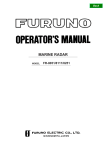
1
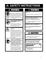
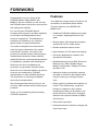
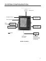
MARINE RADAR
MODEL 851 MARK-2
C
Yo u r L o c a l A g e n t/D e a le r
9-52, A shihara-cho,
N ishinom iya, Japan
Te l e p h o n e :
Te l e f a x :
0 7 9 8 -6 5 -2 111
0798-65-4200
A ll rig h ts re s e rv e d .
Printed in Japan
PUB. No. OM E-34900
(YO SH )
M O DEL 851 M ARK-2
FIRST
EDITIO N
D
:
:
JUN.
JUL.
2000
9, 2001
SAFETY INSTRUCTIONS
WARNING
Do not open the equipment.
Hazardous voltage which can
cause electrical shock, burn or
serious injury exists inside the
ELECTRICAL equipment. Only qualified
personnel should work inside
SHOCK
the equipment.
HAZARD
Wear a safety belt and hard
hat when working on the
antenna unit.
Serious injury or death can
result if someone falls from
the radar antenna mast.
Stay away from transmitting
antenna.
The radar antenna emits microwave radiation which can
be harmful to the human body,
particularly the eyes. Never
look directly into the antenna
radiator from a distance of
less than 1 m when the radar
is in operation.
Turn off the radar power
switch before servicing the
antenna unit. Post a warning sign near the switch
indicating it should not be
turned on while the antenna
unit is being serviced.
Prevent the potential risk of
someone begin struck by the
rotating antenna and exposure to RF radiation hazard.
WARNING
Do not disassemble or modify the
equipment.
Fire, electrical shock or serious injury can
result.
Turn off the power immediately if water
leaks into the equipment or the
equipment is emitting smoke or fire.
Fire or equipment damage can result if a
different cable is used.
Keep heater away from equipment.
Heat can alter equipment shape and melt
the power cord, which can cause fire or
electrical shock.
CAUTION
Use the proper fuse.
Use of a wrong fuse can result in fire or
permanent equipment damage.
A warning label is attatched to the
display unit. Do not remove the label.
If the label is missing or damaged,
contact a FURUNO agent or dealer.
WARNING
To avoid electrical shock,
do not remove cover.
No user-serviceable parts
inside.
Name: Warning Label (2)
Type: 03-129-1001-0
Code No.: 100-236-740
i
TABLE OF CONTENTS
FOREWORD.......................................... iv
SYSTEM CONFIGURATION .................. v
1. PRINCIPLE OF OPERATION
1.1 What is Radar?........................... 1-1
1.2 How Ships Determined Position
Before Radar.............................. 1-1
1.3 How Radar Determines Range... 1-1
1.4 How Radar Determines
Bearing....................................... 1-1
1.5 Radar Wave Speed and Antenna
Rotation Speed .......................... 1-2
1.6 The Radar Display...................... 1-2
2. OPERATION
2.1 Control Description ..................... 2-1
2.2 Display Indications and
Markers ...................................... 2-2
2.3 Turning the Radar On and Off .... 2-2
2.4 Transmitting................................ 2-3
2.5 Selecting the Range ................... 2-3
2.6 Adjusting LCD Backlighting and
Display Tone............................... 2-3
2.7 Adjusting Control Panel
Illumination ................................. 2-4
2.8 Adjusting GAIN, STC, A.C RAIN
and FTC ..................................... 2-4
2.9 Tuning the Receiver ................... 2-6
2.10 Measuring the Range ............... 2-6
2.11 Measuring the Bearing ............. 2-7
2.12 Menu Operation........................ 2-8
2.13 Selecting the Display Mode .... 2-10
2.14 The Window Display............... 2-11
2.15 Selecting the Presentation
Mode ........................................ 2-12
2.16 Guard Alarm ........................... 2-12
2.17 Suppressing Radar
Interference .............................. 2-14
ii
2.18 Suppressing Noise
Interference ............................. 2-15
2.19 Selecting Pulselength............. 2-15
2.20 Off Centering the Display ....... 2-15
2.21 Echo Trails ............................. 2-16
2.22 Navigation Data Display......... 2-17
2.23 Echo Stretch (magnifying
long range echoes) .................. 2-18
2.24 Selecting Unit of
Measurement for Range .......... 2-19
2.25 Selecting Bearing Reference.. 2-19
2.26 Watchman.............................. 2-19
2.27 Erasing the Heading Marker... 2-20
2.28 Deselecting Ranges ............... 2-20
2.29 Displaying Navigation Data
During Stand-by....................... 2-20
2.30 Outputting Cursor Position to
Navigator ................................. 2-21
2.31 Displaying Cursor Position,
Range and Bearing to Cursor .. 2-21
2.32 Visual Alarm Indications......... 2-21
3. INTERPRETING THE DISPLAY
3.1 The Radar Wave and Radar
Horizon ...................................... 3-1
3.2 Target Properties and Radar
Wave Reflection......................... 3-2
3.3 Range Resolution ...................... 3-2
3.4 Bearing Resolution..................... 3-2
3.5 False Echoes ............................. 3-3
3.6 SART ......................................... 3-5
3.7 Racon (Radar Beacon) .............. 3-7
4. MAINTENANCE &
TROUBLESHOOTING
4.1 Preventative Maintenance.......... 4-1
4.2 Replacing the Fuse .................... 4-2
4.3 Troubleshooting ......................... 4-2
4.4 Test ............................................ 4-3
4.5 Replacing the magnetron ........... 4-3
MENU TREE....................................... A-1
SPECIFICATIONS ............................ SP-1
INDEX .......................................... index-1
Declaration of Conformity
iii
FOREWORD
Congratulations on your choice of the
FURUNO Marine Radar MODEL 851
MARK-2. We are confident you will see why
the FURUNO name has become synonymous
with quality and reliability.
For over 50 years FURUNO Electric
Company has enjoyed an enviable reputation
for innovative and dependable marine
electronics equipment. This dedication to
excellence is furthered by our extensive
global network of agents and dealers.
Your radar is designed and constructed to
meet the rigorous demands of the marine
environment. However, no machine can
perform its intended function unless properly
installed and maintained. Please carefully
read and follow the recommended procedures
for installation, operation and maintenance.
While this unit can be installed by the
purchaser, any purchaser who has doubts
about his or her technical abilities may wish to
have the unit installed by a FURUNO
representative or other qualified technician.
The importance of a thorough installation
cannot be overemphasized.
We would appreciate hearing from you, the
end-user, about whether we are achieving our
purposes.
Thank you for considering and purchasing
FURUNO equipment.
Features
Your radar has a large variety of functions, all
contained in a remarkably small cabinet.
The main features of the MODEL 851
MARK-2 are:
• Traditional FURUNO reliability and quality
in a compact, lightweight and low-cost
radar.
• Smartly styled, light-weight and compact
antenna fits even on small yachts.
• Durable brushless antenna motor.
• High definition 8" LCD raster-scan display.
• On-screen alphanumeric readout of all
operational information.
• Standard features include EBL (Electronic
Bearing Line), VRM (Variable Range
Marker), Guard Alarm, Display Off Center
and Echo Trail.
• Watchman feature periodically transmits
the radar to check for radar targets which
may be entering (or exiting) the alarm
zone.
• Ship’s position in latitude and longitude (or
Loran C Time Differences), range and
bearing to a waypoint, ship’s speed,
heading and course can be shown in the
bottom text area. (Requires a navigation
aid which can output such data in NMEA
0183 format.)
• Zoom feature provided.
• Omnipad makes the selection of target and
menu items easy.
iv
SYSTEM CONFIGURATION
Antenna unit
Navigation Device
Remote Display
FMD-811
Echo Sounder
Gyrocompass
Gyro Converter
AD-100
External Alarm
Buzzer OP03-169
Integrated Heading
Sensor PG-1000
Rectifier
RU-3423
Option
Ship's Mains
12-24 VDC
Ship's Mains
100/110/115 VAC
200/220/230 VAC
1φ, 50/60 Hz
MODEL 851 MARK-2
v
1. PRINCIPLE OF OPERATION
1.1 What is Radar?
The term "RADAR" is an acronym meaning
RAdio Detection And Ranging. It is a
device which measures the time it takes for
a pulsed signal to be reflected back from
an object.
1.2 How Ships Determined
Position Before Radar
The use of echoes to determine position
did not begin with radar. Ships would sound
a short blast on their whistles, fire a shot, or
strike a bell as an aid to navigation when
running in fog near a rugged shoreline. The
time between the origination of the sound
and the returning of the echo indicated how
far the ship was from the cliffs or the shore.
The direction from which the echo was
heard indicated the relative bearing of the
shore.
1.3 How Radar Determines
Range
Radar determines the distance to the target
by calculating the time difference between
the transmission of a radar signal and the
reception of the reflected echo. It is a
known fact that radar waves travel at a
nearly constant speed of 162,000 nautical
miles per second. Therefore the time
required for a transmitted signal to travel to
the target and return as an echo to the
source is a measure of the distance to the
target. Note that the echo makes a
complete round trip, but only half the time
of travel is needed to determine the oneway distance to the target. This radar
automatically takes this into account in
making the range calculation.
1.4 How Radar Determines
Bearing
The bearing to a target found by the radar
is determined by the direction in which the
radar antenna is pointing when it emits an
electronic pulse and then receives a
returning echo. Each time the antenna
rotates pulses are transmitted in the full
360 degree circle, each pulse at a slightly
different bearing from the previous one.
Therefore, if one knows the direction in
which the signal is sent out, one knows the
direction from which the echo must return.
1-1
1.5 Radar Wave Speed and
Antenna Rotation Speed
1.6 The Radar Display
Targets are displayed on what is called a
Plan Position Indicator (PPI). This display
is essentially a polar diagram, with the
transmitting ship’s position at the center.
Images of target echoes are received and
displayed at their relative bearings, and at
their distance from the PPI center.
The speed of the radar waves out to the
target and back again as echoes is
extremely fast compared to the speed of
rotation of the antenna. By the time radar
echoes have returned to the antenna, the
amount of antenna rotation after initial
transmission of the radar pulse is
extremely small.
With a continuous display of the images of
targets, the motion of the transmitting ship
is also displayed.
Heading marker
Targets
A
D
B
C
Own ship
(radar)
(A) Bird's eye view of situation
A
D
B
C
Own ship
in center
(B) Radar picture of (A)
Figure 1-1 How radar works
1-2
Range and bearing
of a target, relative
to own ship, are
readable on the PPI.
2. OPERATION
2.1 Control Description
Omnipad
Shifts cursor, VRM
and EBL; selects
items and options
on menu.
Registers selection
on menus.
Adjusts GAIN,
STC, A.C RAIN
and FTC.
ENT
MENU
ECHO
HM
OFF
Opens/closes menus.
Erases heading marker;
selects cursor data (Lat/Long, R/B);
outputs cursor position.
Selects radar range.
RANGE
Adjusts display
tone.
TONE
BRILL
Adjusts display brilliance.
Turns the EBL
on/off.
EBL
VRM
Turns the VRM on/off.
TRAIL
RINGS
Sets guard
zone area.
GUARD
OFF
CENTER
Selects display mode;
erases heading error
indication.
DISP
MODE
ST-BY
TX
Plots targets' trails.
POWER
Turns the range
rings on/off.
Off centers
the display.
Sets radar in stand-by;
transmits radar pulse.
Turns power on/off.
Figure 2-1 Control panel
2-1
2.2 Display Indications and Markers
Heading (requires
heading data)
Range
1.5
0.5
Range ring interval
Presentation mode
Off center
Pulsewidth
Heading marker
CU
Echo trail, AUTO tuning
Echo trail elapsed time,
echo trail time, tuning
indicator
AUTO
HDG 326.8˚ TRAIL
0:00 15S
NM
G ( IN )
FTC1
OFF
CENTER
ES
IR
SP
Guard zone
FTC
(rain clutter suppressor)
Echo stretch
Interference rejector
Guard zone
area
Range rings
Cursor
EBL
VRM
VRM
EBL
+ CURSOR
0.675NM 232.5˚ R 0.681NM 308.7˚ R
VRM
range
EBL
bearing
Cursor
range
}
Range and bearing to
cursor or cursor position in
latitude and longitude may
be displayed by pressing
the [HM OFF] key.
Cursor
bearing
Figure 2-2 Display indications
2.3 Turning the Radar On and
Off
Press the [POWER] key to turn the radar
on or off. The control panel lights and a
timer displays the time remaining for warm
up of the magnetron (the device which
produces radar pulses), counting down
from 1:30.
2-2
Note: When the power is reapplied within a
certain amount of time and circuits
remain charged, the warmup process
is skipped—you can transmit without
one and a half minutes st-by time.
!
WARNING
The radar antenna emits high frequency radio
radiation which can be harmful, particularly to
your eyes. Never look directly at the antenna
from a distance of less than three feet when
the radar is in operation. Always make sure
no one is near the antenna before turning on
the radar.
Note: When the heading signal is lost, the
HDG readout at the top of the screen
shows ***.*. This warning stays on
when the heading signal is restored
to warn the operator that the readout
may be unreliable. After confirming
the heading readout (if necessary,
adjust it), the warning may be erased
by pressing the [DISP MODE] key.
Tips for selecting the range
2.4 Transmitting
2.6 Adjusting LCD
Backlighting and Display
Tone
After the power is turned on and the
magnetron has warmed up, ST-BY (StandBy) appears at the screen center. This
means the radar is now fully operational. In
stand-by the radar is available for use at
anytime—but no radar waves are being
transmitted.
Press the [ST-BY TX] key to transmit.
When transmitting, any echoes reflected
from targets appear on the display. This
radar displays echoes in four tones of gray
according to echo strength.
• When navigating in or around crowded
harbors, select a short range to watch
for possible collision situations.
• If you select a lower range while on
open water, increase the range
occasionally to watch for vessels that
may be heading your way.
The [BRILL] key adjusts the LCD
backlighting in eight levels, including off.
The [TONE] key adjusts the tone (contrast)
of the display in 32 levels, including off.
Procedure
1. Press the [BRILL] key (or [TONE] key).
The display shown in Figure 2-3
appears.
When you won’t be using the radar for an
extended period but want to keep it in a
state of readiness, press the [ST-BY TX]
key to set the radar in stand-by.
2.5 Selecting the Range
The range selected automatically
determines the range ring interval, the
number of range rings, pulselength and
pulse repetition rate, for optimal detection
capability in short to long ranges.
Procedure
Press the [– RANGE +] key. The range and
range ring interval appear at the top left
corner on the display.
BRILL
UP
TONE
DOWN
Tone
setting
19
TONE
UP
BRILL
DOWN
7
<MENU> TO EXIT
Item selected
for adjustment
LCD brilliance
setting
Figure 2-3 Display for adjustment of
brilliance and tone
2. Press the [BRILL] key (or [TONE] key)
to set level. For fine adjustment, press
omnipad at 12 o'clock/6 o'clock for
brilliance and 3 o'clock/9 o'clock for
tone.
2-3
2.7 Adjusting Control Panel
Illumination
Procedure
2. Press the omnipad at 6 o’clock/12
o’clock to select item to adjust. Current
selection is circumscribed by dashed
rectangle.
1. Press the [MENU] key.
3. Press the [ENT] key.
2. Press the omnipad at 6 o’clock to
select Backlight/Brilliance and press
the [ENT] key.
4. Press the omnipad at 3 o’clock/9
o’clock to set level.
3. Press the omnipad at 6 o’clock to
select Panel.
4. Press the omnipad at 3 o’clock/9
o’clock to select illumination level; 4 is
the highest.
5. Press the [ENT] key followed by the
[MENU] key.
2.8 Adjusting GAIN, STC, A.C
RAIN and FTC
General procedure
The [ECHO] key enables adjustment of the
GAIN, STC, A.C RAIN and FTC.
1. Press the [ECHO] key. The following
display appears.
Select auto or manual by
pressing the omnipad at
6 o'clock or 12 o'clock and
pressing [ENT] key.
GAIN ◆ [
STC ◆ [
AUTO
MAN
01
Item selected
AUTO 1 2 3 for adjustment
MAN
A.C
RAIN
FTC
01
ECHO KEY
TO EXIT
Select item/option
by pressing appropriate
omnipad arrow.
00
012
Select auto or
manual by
pressing the
omnipad at
6 o'clock or
12 o'clock and
pressing [ENT]
key.
Current level
Figure 2-4 Display for adjustment of GAIN,
STC, A.C RAIN and FTC
2-4
5. Press the [ECHO] key to finish.
How to adjust the GAIN (sensitivity)
The GAIN works in precisely the same
manner as the volume control of a
broadcast receiver, amplifying the signals
received.
You can adjust the GAIN automatically or
manually. If you select AUTO, the GAIN
automatically adjusted. The range of the
GAIN adjustment is from 1 to 3; 3 is the
highest. For manual adjustment, adjust the
sensitivity on the highest range—the
background noise is clearer on that range.
The range of GAIN adjustment is from 01
to 41. The proper setting is such that the
background noise is just visible on the
screen. If you set up for too little GAIN,
weak echoes may be missed.
On the contrary excessive GAIN yields too
much background noise; strong targets
may be missed because of the poor
contrast between desired echoes and the
background noise on the display.
How to adjust STC (suppressing
sea clutter)
Echoes from waves can be troublesome,
covering the central part of the display with
random signals known as sea clutter. The
higher the waves, and the higher the
antenna above the water, the further the
clutter will extend. Sea clutter appears on
the display as many small echoes which
might affect radar performance. (See the
left-hand figure in Figure 2-5).
The STC reduces the amplification of
echoes at short ranges (where clutter is the
greatest) and progressively increases
amplification as the range increases, so
amplification will be normal at those ranges
where there is no sea clutter. The control is
effective up to about 4 miles.
STC can be adjusted automatically or
manually. If you select AUTO, the STC
automatically adjusted. The range of STC
adjustment is from 1 to 3; 3 is the highest.
For manual adjustment, first adjust the gain
and then transmit on short range. The
range of STC adjustment is from 00 to 50.
Adjust the STC level such that the clutter is
broken up into small dots, and small targets
become distinguishable. If the setting is set
too low, targets will be hidden in the clutter,
while if it is set too high, both sea clutter
and targets will disappear from the display.
In most cases adjust so clutter has
disappeared to leeward, but a little is still
visible windward.
If there is no clutter visible on the display,
turn off the circuit.
Sea clutter at
display center
STC adjusted;
sea clutter suppressed.
Figure 2-5 Effect of STC
How to adjust A.C RAIN and FTC
(suppressing rain clutter)
The vertical beamwidth of the antenna is
designed to see surface targets even when
the ship is rolling. However, by this design
the unit will also detect rain clutter (rain,
snow, hail, etc.) in the same manner as
normal targets. Figure 2-6 shows the
appearance of rain clutter on the display.
Adjusting A.C RAIN
When rain clutter masks echoes over a
wide range, raise the A.C RAIN slightly to
distinguish targets from the clutter.
Appearance of
rain clutter
A.C RAIN adjusted;
rain clutter suppressed.
Figure 2-6 Effect of A.C RAIN
2-5
Adjusting FTC
Manual tuning
To suppress rain clutter from heavy storms
or scattered rain clutter, adjust the FTC
among 0, 1 and 2 (0 is off). The FTC circuit
splits up these unwanted echoes into a
speckled pattern, making recognition of
solid targets easier. FTC and selected level
appear at the top right-hand corner of the
display when the circuit is turned on.
The default tuning method is automatic. To
switch to manual tuning;
Note: In addition to reducing clutter, the
FTC can be used in fine weather to
clarify the picture when navigating in
confined waters. However, with the
circuit activated the receiver is less
sensitive. Therefore, turn off the
circuit when its function is not
required.
1. Press the [MENU] key to open the
menu.
2. Press the omnipad at 6 o’clock to
select Tuning.
3. Press the omnipad at 3 o’clock to
select MANUAL.
4. Press the [ENT] key followed by the
[MENU] key.
How to tune manually
While pressing and holding down the [HM
OFF] key, press the 9 o'clock or 3 o'clock
position on the omnipad to tune. Tune to
show the longest tuning indicator.
2.9 Tuning the Receiver
The receiver can be tuned automatically or
manually. For automatic tuning the receiver
is tuned each time you switch from standby to transmit. For manual tuning, the
receiver is properly tuned when the longest
tuning indicator appears. (However, the
length of the indicator changes with the
number of radar echoes, range and other
factors.)
0.5
1.5NM
Tuning
indicator
AUTO
2.10 Measuring the Range
You can measure the range to a target
three ways: by the range rings, by the
cursor, and by the VRM (Variable Range
Marker).
By range rings
Press the [RINGS] key to display the range
rings. Count the number of rings between
the center of the display and the target.
Check the range ring interval (at the top left
corner) and judge the distance of the echo
from the inner edge of the nearest ring.
By cursor
Figure 2-7 Tuning indicator
Note:When you switch from manual to
automatic, wait 4 seconds before
closing the MENU. Otherwise
automatic tuning may not work
properly.
2-6
Operate the omnipad to place the cursor
intersection on the inside edge of the target
echo. The range to the target, as well as
the bearing, appears at the bottom of the
display.
By VRM
2.11 Measuring the Bearing
1. Press the [VRM] key to display the
VRM.
There are two ways to measure the bearing
to a target: by the cursor, and by the EBL
(Electronic Bearing Line).
2. Press the omnipad to place the VRM
on the inside edge of the target.
3. Check the VRM readout at the bottom
left-hand corner of the display to find
the range to the target.
Note: The VRM is automatically anchored
if the omnipad is not operated within
about 10 seconds.
To erase the VRM, press and hold down
the [VRM] key for about two seconds.
0.5
1.5NM
Operate the omnipad to bisect the target
with the cursor intersection. The bearing to
the target appears at the bottom right-hand
corner of the display.
By EBL
1. Press the [EBL] key to display the EBL.
2. Press the omnipad to bisect the target
with the EBL.
3. Check the EBL readout at the bottom
left-hand corner of the display to find
the bearing to the target.
Target
Note: The EBL is automatically anchored if
the omnipad is not operated within
about 10 seconds.
To erase the EBL, press and hold down
the [EBL] key for about two seconds.
VRM
VRM
range
By cursor
VRM
EBL
0.675NM 220.9¡ R
0.5
+ CURSOR
1.5NM
0.675NM 308.7˚ R
Target
Figure 2-8 Measuring range by the VRM
EBL
VRM
EBL
0.675 NM 300.1˚ R
+ CURSOR
0.675NM 300.1˚ R
EBL
bearing
Figure 2-9 Measuring bearing by the EBL
2-7
Tips for measuring the bearing
2.12 Menu Operation
• Bearing measurements of smaller
targets are more accurate; the center of
larger target echoes is not as easily
identified.
The menu, consisting of six sub menus,
mostly contains less-often used functions
which once preset do not require regular
adjustment. To open or close the menu,
press the [MENU] key. You can select
items and options on the menu with the
omnipad.
• Bearings of stationary or slower moving
targets are more accurate than bearings
of faster moving targets.
• To minimize bearing errors keep echoes
in the outer half of the picture by
changing the range scale; angular
difference becomes difficult to resolve
as a target approaches the center of the
display.
Target on Collision course with your
vessel?
You can determine if a target might be
on a collision course with your vessel by
placing the EBL on the target. If it tracks
along the EBL as it approaches the
screen center it may be on a collision
course with your vessel.
Basic menu operation
1. Press the [MENU] key to open the main
menu.
● MAIN MENU ●
Select item by ▲▼ keys
and press ENT key.
1. Backlight/Brilliance
2. P/L, IR, NR & Radar Mode
3. Nav Data
4. Mode & Function
5. Tuning
AUTO MANUAL
6. Self Check
7. Installation Setup 1
...................
Press HM-OFF to temporarily
hide menu.
<Press MENU key to escape>
Figure 2-10 Main menu
2. Press the omnipad at 6 o’clock/12
o’clock to select menu and press the
[ENT] key.
3. Press the omnipad at 6 o’clock/12
o’clock to select a menu item.
4. Press the omnipad at 3 o’clock/9
o’clock to select an option.
5. Press the [ENT] key to register
selection.
6. Press the [MENU] key to close the
menu.
2-8
Menu description
Table 2-1 Menu description
Menu
● BACKLIGHT/BRILLIANCE MENU ●
Select item and option
by ▲▼ keys.
1. Panel
1 2 3 4
2. Echo Trail
1 2
Function
1. Selects control panel backlighting; four is
maximum backlighting.
2. Selects brilliance for echo trails and
markers; two is maximum brilliance.
........................................
Press HM-OFF to temporarily
hide menu.
<Press MENU for main menu.>
● P/L, IR, NR & Radar Mode ●
Select item and option
by ▲▼ keys.
1. Pulselength SHORT LONG
2. Int Reject
OFF 1 2 3
3. Noise Reject OFF ON
4. Echo Stretch OFF ON
5. Radar Mode CU WPT-UP
........................................
Press HM-OFF to temporarily
hide menu.
<Press MENU for main menu.>
● NAV DATA MENU ●
Select item and option
by ▲▼ keys.
1. Navigator
ALL GPS LC
2. Nav Data Disp OFF ON
3. Pos Disp Mode L/L TD
4. Depth Unit
M FA FT
5. Temp Unit
˚C ˚F
6. STBY Display NORM NAV
........................................
Press HM-OFF to temporarily
hide menu.
<Press MENU for main menu.>
● MODE & FUNCTION MENU ●
Select item and option
by ▲▼ keys.
1. Window Display Zoom Wide
OFF 5' 10' 20'
2. Watchman
IN OUT
3. Alarm Mode
NM KM SM
4. VRM Unit
REL TRUE
5. EBL Ref
1/8
1/4 1/2 3/4 1 1.5
6. Range
2 3 4 6 8 12 16 24 36 48
........................................
Press HM-OFF to temporarily
hide menu.
<Press MENU for main menu.>
Tuning
Self Check
1. Selects pulselength for 1.5 and 3 mile
ranges.
2. Selects radar interference rejector level; 3
provides highest degree of rejection.
3. Turns noise rejector on/off.
4. Turns echo stretch on/off.
5. Selects presentation mode for CU or
WPT-UP.
1. Selects navigator among GPS, Loran C and
all navigators available. In the "ALL" setting
the radar selects a navigator in order of
navigator accuracy–GPS, Loran and other.
2. Turns navigation data display on/off.
3. Selects position display format; latitude and
longitude or Loran C TDs.
4. Selects unit of measurement for depth;
meters, feet or fathoms.
5. Selects unit of water temperature
measurement; ˚C or ˚F.
6. Selects what to display during stand-by;
navigation data (requires navigation input)
and "STBY".
1. Selects window display format; zoom or
wide.
2. Selects watchman interval among 5 min,
10 min and 20 min.
3. Selects alarm mode; IN (alarm to targets
entering the guard zone, or OUT (alarm to
targets exiting the guard zone.
4. Selects VRM unit; nm, km or sm.
5. Selects EBL reference; relative to the
ship's heading or true.
6. Selects ranges to use. (At least two are
selected.)
Select range to enable (disable) and press
[ENT] key.
Selects AUTO or MANUAL tuning.
Checks the radar system for proper operation.
* Default settings shown in reverse video.
2-9
2.13 Selecting the Display
Mode
The display mode may be selected with the
[DISP MODE] key. Four modes are
available (with navigation input): Normal,
Normal + Window, Normal + Nav Data, and
Normal + Window + Nav Data.
Window Display
Nav Display
Each time the key is pressed the display
mode changes in one of the sequences
shown below, depending on equipment
connected and menu settings.
WIDE / ZOOM
ON
/ OFF
Window display
(Zoom or Wide)
ZOOM
VRM
EBL
**.** NM ***.*˚R
+CURSOR
***.**NM ***.*˚ R
VRM
EBL
**.** NM ***.*˚R
Normal
Window Display
Nav Display
+CURSOR
***.**NM ***.*˚ R
Normal + Window
WIDE / ZOOM
ON
/ OFF
ZOOM
Nav data
VRM
EBL
**.** NM ***.*˚R
+CURSOR
***.**NM ***.*˚ R
Normal + Nav Data
VRM
EBL
**.** NM ***.*˚R
Normal + Window + Nav Data
Figure 2-11 Display modes
2-10
+CURSOR
***.**NM ***.*˚ R
2.14 The Window Display
The window display appears at the bottom
left (or right) 1/4 of the display. Two types of
window displays are available: zoom and
wide. Zoom doubles the size of the area
selected by the operator, and wide (rangeup) compresses and displays the entire
radar picture from the next higher range.
3. Press the [ENT] key to confirm the
zoom area in the window display. The
area selector becomes a dashed circle
and the cursor can be moved
independently.
To reselect area to zoom, press [ENT] or
[DISP MODE] and follow steps 2 and 3.
Area selector (1/4 or 1/3 of range)
Note 1: The zoom display does not
function on the 0.125 and 0.25 nm
ranges.
Note 2: The wide display does not function
on the 48 nm range.
Window
display
area
Zoom
Selecting the type of window
display
1. Press the [MENU] key.
Zoom
VRM
EBL
**.** NM ***.*˚R
VRM
EBL
**.** NM ***.*˚R
+CURSOR
***.**NM ***.*˚ R
(1) Press [DISP MODE]
to select the window
display.
+CURSOR
***.**NM ***.*˚ R
(2) Use the omnipad
to select area to zoom
and press [ENT].
Figure 2-12 How to select
the area to zoom
2. Press the omnipad at 6 o’clock to
select Mode & Function and press the
[ENT] key.
3. Press the omnipad at 6 o’clock to
select Window Display to Zoom or
Wide as appropriate.
4. Press the [ENT] key followed by the
[MENU] key.
Selecting the area for the zoom
picture
WIDE
VRM
EBL
**.** NM ***.*˚R
+CURSOR
***.**NM ***.*˚ R
Wide display
The entire picture on
the next higher range.
Figure 2-13 Example of wide display
1. Press the [DISP MODE] key to select
the window display. The area selector, a
solid circle, appears.
2. Use the omnipad to place the area
selector on the area to zoom.
Note: When you place the area selector
behind the window display, the
window display shifts right (or left) so
you may view the circle cursor.
2-11
WPT-UP (waypoint-up)
2.15 Selecting the
Presentation Mode
This radar provides four presentation
modes: head-up, course-up (course-up or
waypoint-up; selectable on menu), northup and true motion (requires heading
sensor). Press the [DISP MODE] and [HM
OFF] keys together to select a presentation
mode. Each time the keys are pressed, if
heading signal is input to the radar, the
presentation mode changes in the
sequence of HU, CU (or WU), NU, TM. If
there is no heading signal input to the radar,
the presentation mode is always HU.
Note: TM does not function on the 48 nm
range.
WPT-UP
(waypoint-up)
Procedure
1. Press the [MENU] key to open the
menu.
2. Press the omnipad at 6 o’clock to
select 2. P/L, IR, NR & Radar Mode.
3. Press the [ENT] key.
CU
(course-up)
HU
(head-up)
An azimuth stabilized display in which the
line connecting the center with the top of
the display indicates the bearing to the
“TO” waypoint, which is selected on the
navigational equipment connected to the
radar. When navigating a route and own
ship enters the arrival zone of a waypoint,
the radar displays the bearing to the next
“TO” waypoint.
NU
(north-up)
TM
(true motion)
Selecting course-up mode for CU
or WPT-UP
You may select WPT-UP instead of CU on
the menu.
4. Press the omnipad at 6 o’clock to
select Radar Mode.
5. Press the omnipad at 3 o’clock/9
o’clock to select the option CU or
WPT-UP as desired.
6. Press the [ENT] key followed by the
[MENU] key.
CU (course-up)
2.16 Guard Alarm
An azimuth stabilized display in which a
line connecting the center with the top of
the display indicates own ship’s intended
course (namely, own ship’s previous
heading just before this mode has been
selected).
The guard alarm allows the operator to set
the desired range and bearing for a guard
zone. When ships, islands, landmasses,
etc. enter (or exit, depending on type of
guard zone in use) the guard zone an
audible alarm sounds to call the operator’s
attention. The alarm is very effective as an
anticollision aid when using an autopilot or
navigating in narrow channels.
Target pips are painted at their measured
distances and in their directions relative to
the intended course which is maintained at
the 0-degree position while the heading
line moves in accordance with ship’s
yawing and course change. This mode is
useful to avoid smearing of picture during
course change.
2-12
CAUTION
The guard alarm is a useful anti-collision aid,
but does not relieve the operator of the
responsibility to also keep a visual lookout
for possible collision situations. The alarm
should never be used as the sole means for
detecting possible collision situations.
Selecting guard zone type
The guard alarm can be set to sound on
targets entering (guard in) or exiting (guard
out) the guard zone. Select type of guard
zone as follows.
1. Press the [MENU] key to display the
menu.
2. Press the omnipad at 6 o’clock to
select Mode & Function and press the
[ENT] key.
3. Press the omnipad at 6 o’clock to
select Alarm Mode.
4. Press the omnipad at 3 o’clock/9
o’clock to select IN or OUT as
appropriate.
5. Press the [ENT] key followed by the
[MENU] key.
Setting the guard zone
1. Mentally create the guard zone you
want to display. See Figure 2-15 (1).
2. Operate the omnipad to set cursor on
top (bottom) left edge of the guard zone.
Press the [GUARD] key. *G (IN) (or G
(OUT)), with asterisk blinking, appears
at the top right-hand corner on the
display. (The asterisk indicates the
guard zone is partially set.) See Figure
2-15 (2).
3. Operate the omnipad to set cursor on
bottom (top) right edge of the guard
zone and press the [GUARD] key. The
asterisk disappears. See Figure 2-15
(3).
4. Guard zone appears on the display.
See Figure 2-15 (4).
Silencing the audible alarm
Any ships, landmasses, etc. coming into
(or going out of) the guard zone will trigger
the audible alarm and display the guard
zone in reverse video. You can silence the
alarm by pressing the [GUARD] key. When
this is done, G (ACKN) replaces G (IN) (or
G (OUT)).
Press the [GUARD] key again to reactivate
the alarm. G (IN) (or G (OUT)) replaces G
(ACKN).
Dashed line:
no alarm
Guard
zone
IN ALARM
OUT ALARM
Figure 2-14 In and out alarms
2-13
Canceling the guard zone
Press and hold down the [GUARD] key
until the guard zone disappears.
Notes on the guard alarm
• When the radar range is less than one
half of the guard zone range, the guard
zone disappears from the display and
G (IN) (or G (OUT)) is displayed in
reverse video. If this happens, raise the
range to redisplay the guard zone.
• A target echo does not always mean a
landmass, reef, ships or surface objects
but can imply returns from sea surface
or precipitation. As the level of these
returns varies with environment, the
operator should properly adjust the STC,
GAIN (sensitivity), A. C RAIN and FTC
to be sure the alarm system does not
overlook target echoes.
2.17 Suppressing Radar
Interference
Radar interference may occur when near
another shipborne radar operating in the
same frequency band as your radar. Its onscreen appearance is many bright dots
either scattered at random or in the form of
dotted lines extending from the center to
the edge of the display. Figure 2-16
illustrates interference in the form of curved
spokes. Interference effects are
distinguishable from normal echoes
because they do not appear in the same
place on successive rotations of the
antenna.
Figure 2-16 Radar interference
Asterisk blinking
Guard zone
to set
* G (IN)
Four levels of interference are available,
including off. 3 provides the highest level of
rejection.
Procedure
Drag cursor
here.
1. Press the [MENU] key.
(1) Mentally create
the guard zone to set.
G (IN)
(2) Drag cursor to
top left corner of
zone and press
[GUARD].
G (IN)
Guard
zone
Drag cursor
here.
(4) Guard zone
completed.
(3) Drag cursor to
bottom right corner
of zone and press
[GUARD].
Figure 2-15 How to set a guard zone
2-14
2. Press the omnipad at 6 o’clock to
select P/L, IR, NR & Radar Mode and
press the [ENT] key.
3. Press the omnipad at 6 o’clock to
select Int Reject.
4. Press the omnipad at 3 o’clock/9
o’clock to select level desired; 3
provides the greatest degree of
interference rejection.
5. Press [ENT] and [MENU] keys.
IR appears at the top right corner on the
display when the interference rejection
circuit is turned on.
2.18 Suppressing Noise
Interference
Noise interference appears on the screen
as many bright dots. These dots can be
suppressed by turning on the noise rejector.
Note however that there are some forms of
noise interference which this radar cannot
suppress.
Procedure
1. Press the [MENU] key.
2. Press the omnipad at 6 o’clock to
select P/L, IR, NR & Radar Mode and
press the [ENT] key.
3. Press the omnipad at 6 o’clock to
select Noise Reject.
4. Press the omnipad at 3 o’clock/9
o’clock to select ON or OFF as
appropriate.
5. Press the [ENT] key followed by the
[MENU] key.
4. Press the omnipad at 3 o’clock/9
o’clock to select SHORT or LONG as
appropriate.
5. Press [ENT] and [MENU] keys.
SP or MP for 1.5 NM range, or MP or LP for
3 NM range appears at the upper left-hand
corner.
2.20 Off Centering the Display
Note: This function is not available on the
48 nm range.
Your vessel’s position can be shifted
anywhere in the effective display area. The
primary advantage of the off centered
display is that for any range setting, the
view ahead of your vessel can be extended
without changing the range or size of
targets.
Procedure
1. Locate the cursor where you want to
the screen center to be.
2.19 Selecting Pulselength
2. Press the [OFF CENTER] key.
Pulselength is the transmission time of a
single radar pulse. The longer the
pulselength the greater the detection range
capability, however range accuracy and
range resolution are reduced.
OFF CENTER appears at the top left
corner on the display when the display is
off centered.
3. To cancel the off center display, press
the [OFF CENTER] key again.
Pulselength can be selected to short or
long on the 1.5 and 3 nautical mile ranges.
1. Press the [MENU] key.
2. Press the omnipad at 6 o’clock to
select P/L, IR, NR & Radar Mode and
press the [ENT] key.
3. Press the omnipad at 6 o’clock to
select Pulselength.
Cursor
(1) Place cursor
where desired.
Cursor
(2) Press [OFF CENTER] key;
cursor location becomes
own ship's position.
Figure 2-17 Off centering the display
2-15
2.21 Echo Trails
Fixed time trails
You can show the trails of targets in
afterglow. This function is useful for alerting
you to possible collision situations.
When the elapsed time clock counts up to
the trail time selected, the elapsed time
display freezes. The oldest portions of trails
are erased so only the latest trail, equal in
length to the trail time selected, is shown.
Then, trails start extending again. For
example, the one minute trail time is
selected. When the elapsed time display
freezes at 60 seconds, all but the latest one
minute of trails are erased and then trailing
continues.
Starting echo trail
Press the [TRAIL] key to start the echo trail
function. Afterglow starts extending from
targets and "TRAIL" and the echo trail time
appear at the top right-hand corner of the
display. Press the key again within 3
seconds to select a different trail time,
among 15 sec, 30 sec, 1 min, 3 min, 6 min,
15 min, 30 min, and continuous. In
continuous plotting the time elapsed
appears at the top right corner on the
display.
Note: If the range is changed, trails are
painted anew with the newly selected
range.
Continuous trail
The maximum continuous trail time is 99
minutes and 59 seconds. When the
elapsed time clock counts up to that time
the elapsed time display is reset to zero, all
trails are erased and then trailing is
restarted.
Adjusting brilliance of afterglow
The brilliance of the trails' afterglow can be
set on the Backlight/Brilliance menu.
1. Press the [MENU] key.
True trails
Relative trails
Figure 2-18 Appearance of echo trails
2. Press the omnipad at 6 o’clock to
select Backlight/Brilliance and press
the [ENT] key.
3. Press the omnipad at 6 o’clock to
select Echo Trail.
4. Select brilliance level, 1 or 2 as desired.
2 is the highest level.
5. Press the [ENT] key followed by the
[MENU] key.
Canceling echo trails
Press the [TRAIL] key to erase the TRAIL
indication.
2-16
2.22 Navigation Data Display
Setting up the nav data display
Navigation data can be displayed at the
screen bottom if this radar receives
appropriate navigation input in NMEA 0183
format. Navigation data includes
1. Press the [MENU] key.
• Position in latitude and longitude or
Loran-C time differences (TDs)
• Bearing and range to a waypoint
selected on the navigator
• Cross track error (XTE-the amount in
nautical miles and the direction the
vessel if off course)
• Depth
Select item and option
by ▲▼ keys.
1. Navigator
ALL GPS LC
2. Nav Data Disp
OFF ON
3. Pos Disp Mode
L/L TD
4. Depth Unit
M FA FT
5. Temp Unit
˚C ˚F
6. STBY Display
NORM NAV
...................
<Press MENU for main menu.>
If the navigation data includes the
destination data, waypoint position is
denoted on the radar display by a dashed
ring.
Waypoint position
1.5NM
● NAV DATA MENU ●
Press HM-OFF to temporarily
hide menu.
• Speed
0.5
2. Press the omnipad at 6 o’clock to
select Nav Data and press the [ENT]
key.
AUTO
HDG 326.8˚
Figure 2-20 Nav data menu
3. Press the omnipad at 6 o'clock to
select Navigator.
4. Press the omnipad at 3 o'clock/9
o'clock to select ALL, GPS or LC as
appropriate and press the [ENT] key.
(Select ALL if several navigators are
connected to the radar. In this case,
position data is selected in order of
GPS, Loran C and other.)
5. Press the omnipad at 6 o'clock to
select Nav Data Disp.
DEPTH
XTE
350.0m
WAYPOINT
1.8 NM
VRM
SPD
0.05NML 30.0KT
25˚ M
EBL
0.675NM 240.1˚ R
POSI L/L
66˚ 04. 00N
166˚ 04. 00E
+ CURSOR
0.646 NM 308.7˚ R
Figure 2-19 Sample nav data display
6. Press the omnipad at 3 o'clock/9
o'clock to select ON or OFF as
appropriate and press the [ENT] key.
7. Press the omnipad at 6 o'clock to
select Pos Disp Mode.
8. Press the omnipad at 3 o'clock/9
o'clock to select L/L (latitude and
longitude) or TD (Loran C) as
appropriate and press the [ENT] key.
9. Press the omnipad at 6 o'clock to
select Depth Unit.
2-17
10. Press the omnipad at 3 o'clock/9
o'clock to select M (meters), FA
(fathoms) or FT (feet) as desired and
press the [ENT] key.
11. Press the omnipad at 6 o'clock to
select Temp Unit.
12. Press the omnipad at 3 o'clock/9
o'clock to select °C or °F as desired
and press the [ENT] key.
13. Press the omnipad at 6 o'clock to
select STBY Display.
14. Press the omnipad at 3 o'clock/9
o'clock to select NORM (navigational
data is not displayed) or NAV
(navigational data is displayed as
desired) and press the [ENT] key.
15. Press the [MENU] key to escape.
2.23 Echo Stretch (magnifying
long range echoes)
Normally, the reflected echoes from long
range targets appear on the display as
weaker and smaller blips even though they
are compensated by the radar’s internal
circuitry. To stretch long range echoes, in
the range direction, turn on the echo
stretch function.
Distant echo
Echo stretch OFF
Echo stretch ON
Figure 2-21 Echo stretch
2-18
Turning echo stretch on or off
1. Press the [MENU] key.
2. Press the omnipad at 6 o’clock to
select P/L, IR, NR & Radar Mode and
press the [ENT] key.
3. Press the omnipad at 6 o’clock to
select Echo Stretch.
4. Press the omnipad at 3 o’clock/9
o’clock to select ON or OFF as
appropriate.
5. Press the [ENT] key followed by the
[MENU] key. ES appears at the top
right side on the display when the echo
stretch feature is on.
Note 1: This function magnifies not only
targets but also sea clutter and
radar interference. For this reason
be sure the controls for adjustment
of sea clutter and radar interference
are properly adjusted before
activating the echo stretch.
Note 2: Echo stretch is inoperative on
ranges from 0.125 to 0.5 nautical
miles.
Note 3: When the echo stretch function is
selected, the equipment
automatically selects interference
rejection level #3 and turns on the
noise rejector. These can be turned
off via the menu if desired.
2.24 Selecting Unit of
Measurement for Range
2.26 Watchman
The unit of measurement for the VRM and
cursor can be nautical miles, kilometers, or
statute miles. You may select unit desired
as follows.
The watchman function periodically
transmits the radar for about one minute to
check for targets in a guard zone. If it finds
change in the zone from the previous
transmission it sounds the aural alarm,
cancels the watchman function, and
transmits the radar continuously. This
feature is useful when you do not need the
radar’s function continuously but want to be
alerted to radar targets in a specific area.
1. Press the [MENU] key.
2. Press the omnipad at 6 o’clock to
select Mode & Function and press the
[ENT] key.
3. Press the omnipad at 6 o’clock to
select VRM Unit.
4. Press the omnipad at 3 o’clock/9
o’clock to select NM, KM, or SM as
desired.
5. Press [ENT] followed by [MENU] key.
2.25 Selecting Bearing
Reference
Bearing can be displayed relative to ship’s
heading (relative bearing) or relative to true
north (true bearing) as follows. (True
bearing requires heading sensor input.)
1. Press the [MENU] key.
2. Press the omnipad at 6 o’clock to
select Mode & Function and press the
[ENT] key.
3. Press the omnipad at 6 o’clock to
select EBL Ref.
4. Press the omnipad at 3 o’clock/9
o’clock to select REL(ATIVE) or TRUE
as appropriate.
5. Press the [ENT] key followed by the
[MENU] key.
How watchman works
Tx
St-by
Tx
St-by
1 min
5, 10 or
20 min
1 min
5, 10 or
20 min
Watchman
starts.
Figure 2-22 How watchman works
Turning on watchman
1. Create a guard zone (usually 360
degrees) with the guard alarm function.
2. Press the [MENU] key.
3. Press the omnipad at 6 o’clock to
select Mode & Function and press the
[ENT] key.
4. Press the omnipad at 6 o’clock to
select Watchman.
5. Press the omnipad at 3 o’clock/9
o’clock to select watchman rest interval
(amount of time until next rotation of
antenna); 5 minutes, 10 minutes or 20
minutes as desired.
6. Press the [ENT] key followed by the
[MENU] key. Then, WATCHMAN
appears, and the radar transmits for
one minute and then goes into standby.
2-19
Canceling watchman
1. Press the [MENU] key.
2. Press the omnipad at 6 o’clock to
select Mode & Function and press the
[ENT] key.
3. Press the omnipad at 6 o’clock to
select Watchman.
4. Press the omnipad at 3 o’clock/9
o’clock to select OFF.
5. Press the [ENT] key followed by the
[MENU] key.
2.27 Erasing the Heading
Marker
The heading marker continuously appears
on the display and shows your vessel’s
heading. When this mark obscures a target
echo, you can temporarily erase it by
pressing and holding down the [HM OFF]
key. Release the key to redisplay the
marker.
2.28 Deselecting Ranges
This radar has 16 ranges, some which you
may not require. You can deselect up to
fourteen ranges as follows.
1. Press the [MENU] key.
2. Press the omnipad at 6 o’clock to
select Mode & Function and press the
[ENT] key.
3. Select Range and press the [ENT] key.
Active ranges appear in reverse video.
4. Press the omnipad at 3 o’clock/9
o’clock to select range to disable (or
enable) and press the [ENT] key.
Current selection is underlined.
5. Press the [ENT] key.
2-20
6. Repeat steps 4 and 5 to disable (or
enable) other ranges.
7. When finished, press the [MENU] key.
2.29 Displaying Navigation
Data During Stand-by
Various navigation data can be displayed
during stand-by. A barometer is built in this
radar; atmospheric pressure appears, in
graph form, on the navigation data display
during stand-by. If your navigation aid can
output data in NMEA 0183 data format,
your vessel’s position in latitude and
longitude, the range and bearing to
waypoint, speed, course, date, time and
cross track error may be input to this radar,
and be seen in the bottom text area during
stand-by. Further, with video sounder input,
depth may be displayed, both digitally and
in graph form.
CAUTION
The barometer and depth displays are intended
as reference. Any data displayed by them should
be used with extreme caution.
Procedure
1. Press the [MENU] key.
2. Press the omnipad at 6 o’clock to
select the Nav Data and press the
[ENT] key.
3. Press the omnipad at 6 o’clock to
select STBY Display.
4. Press the omnipad at 3 o’clock/9
o’clock to select NAV and press the
[ENT] key.
5. Press the [MENU] key.
Note 1: The depth display scale changes
automatically with depth and the
maximum depth is 1,000 meters.
Note 2: The barometer display is updated
hourly, thus the data shown may
not be the latest.
ST–BY
(mbar/hPa)
2 (MIN) 1
0
1020
1010
500
1000
990
-12 -9 -6
(HOUR)
DATE
08.22
TIME
15:19
DEPTH
827 m
WAYPOINT
12.0NM
114.8˚R
The cursor data indication at the bottom of
the display can show cursor position in
latitude and longitude or the range and
bearing from own ship to the cursor. You
can select the indication desired by
pressing the [HM OFF] key.
Navigation data is required to display
latitude/longitude position.
1000
-3
BAROMETER
2.31 Displaying Cursor
Position, Range and
Bearing to Cursor
(m)
DEPTH
TEMP
CRS
XTE
SPD
30.0˚C
0.0˚M
0.6NM R 30.0KT
POSI L/L
65˚43.98N
165˚43.96E
2.32 Visual Alarm Indications
This radar display various visual alarms to
alert you to error.
Table 2-2 Visual alarm indications
Error
Visual alarm
No heading pulse
HD SIG MISSING
No bearing pulse
BRG SIG MISSING
Figure 2-23 Navigation data display during
stand-by
Heading signal
turned off
***.* (appears as
heading)
2.30 Outputting Cursor
Position to Navigator
The heading signal visual alarm may be
cleared by pressing the [DISP MODE] key.
XTE
XTE
L 1
0.5
0 (NM) 0.5
1R
Cursor position (NMEA0183 data sentence
TLL) can be output to the navigator
connected to this radar by pressing and
holding down the [HM OFF] key.
2-21
3. INTERPRETING THE DISPLAY
As an aid to navigation, radar can be a very
valuable tool. No other electronic
navigation aid can give you the ability to
spot vessels coming at you in the fog, or
tell you the location of the inlet to the
harbor in the pitch black of night.
To help you understand what your radar
can (and cannot) do for you this chapter
covers
• the characteristics of the radar wave
• target properties and radar wave
reflection
• range and bearing resolution, and
• false echoes.
3.1 The Radar Wave and Radar
Horizon
How the radar wave travels
The radar wave tends to travel in straight
lines at the speed of light. However, it is
subject to bending or refraction in the
atmosphere, the amount depending on
region and density.
Super-refraction
Super-refraction is a condition in which
there is an upper layer of warm dry air over
a surface layer of cold, moist air. Radar
waves bend downward and thus increase
the ranges at which targets may be
detected.
Sub-refraction
Sub-refraction is the reverse condition of
super-refraction; a layer of cold air is above
a layer of warm air. Radar waves bend
upward and thus decrease the ranges at
which targets may be detected.
Radar horizon
Radar is essentially a “line-of-sight”
phenomenon. That means you have just
about the same range to horizon with a
radar as you do with your own eyes.
However under normal atmospheric
conditions, the radar horizon is 6% greater
than the optical horizon. Therefore, if the
target does not rise above the horizon the
radar beam cannot be reflected from the
target.
The distance to the horizon from the
antenna, under normal conditions, is
calculated by the following formula.
Rmax = 2.2 × h 1 + h 2
Where Rmax: Radar horizon (mile), h1:
Antenna height (meters), h2: Target height
(meters)
D
h2
h1
Horizon
Wave
path
Figure 3-1 Radar horizon
3-1
3.2 Target Properties and
Radar Wave Reflection
Generally, larger targets can be seen on
the radar display at greater ranges,
provided line-of-sight exists between the
scanner and target. However, a large target
with poor reflecting properties may not be
detected as easily as a smaller target with
better reflecting properties. For example,
you might expect a lighthouse to be a good
radar target because of its size. In actuality
the return echo is weak since the conical
shape diffuses most of the radiated energy.
A ship whose hull is made of conducting
materials, such as steel, will return a
relatively strong echo.
On the other hand, hulls made from wood
or fiberglass return much weaker echoes.
Vertical surfaces, such as a cliff, are good
targets provided they face the radar.
Conversely, horizontal and smooth
surfaces such as mudbanks, sandy
beaches, and gently sloping hills make
poor targets because they disperse rather
than reflect most of the energy that strikes
them.
The strongest radar echoes known come
from built-up areas, docks, etc., because
these targets are less subject to changes in
aspect. These types of targets have three
flat, smooth surfaces mutually at right
angles. Some radar buoys are arranged
this way so as to deliberately increase their
detection range.
3-2
3.3 Range Resolution
Range resolution is a measure of the
capability of a radar to display as separate
pips the echoes received from two targets
which are on the same bearing and are
close together.
The main factor which affects range
resolution is pulselength. Two targets on
the same bearing, close together, cannot
be seen as two distinct echoes on the
display unless they are separated by a
distance greater than one-half the
pulselength.
Transmitted
radar
pulse
Transmitted
radar
pulse
Radar is able to display two
distinct target echoes.
Target
Target
Radar cannot display targets as
separate echoes because they
are within the pulselength.
Figure 3-2 Range resolution
3.4 Bearing Resolution
Bearing resolution is a measure of the
capability of a radar to display as separate
targets the echoes received from two
targets which are at the same range and
are close together.
The principal factor which affects bearing
resolution is horizontal beamwidth. Two
targets at the same range must be
separated by more than one beamwidth to
appear as separate pips.
True
echo
Radar is able to display two
distinct target echoes.
Target
Horizontal
beamwidth
Direction of
scanner rotation
Target
Target
Own ship
Multiple
echo
Horizontal
beamwidth
Direction of
scanner rotation
Radar cannot display targets as
separate echoes because they
are within the beamwidth.
Figure 3-3 Bearing resolution
3.5 False Echoes
Occasionally false echoes appear on the
screen at positions where there is no target.
In some cases the effects can be reduced
or eliminated. The operator should
familiarize himself or herself with the
appearance and effects of these false
echoes, so as not to confuse them with
echoes from legitimate contacts.
Figure 3-4 Multiple echoes
Side-lobe echoes
Every time the antenna rotates, some
radiation escapes on each side of the
beam-called “side-lobes.” If a target exists
where it can be detected by the side-lobes
as well as the main-lobe, the side-lobe
echoes may be represented on both sides
of the true echo at the same range, as
shown in Figure 3-5. Side-lobes show
usually only at short ranges and from
strong targets. They can be reduced
through careful reduction of the sensitivity
or proper adjustment of the STC.
True echo
Main-lobe
Multiple echoes
Multiple echoes occur when a short range,
strong echo is received from a ship, bridge,
or breakwater. A second, a third or more
echoes may be observed on the display at
double, triple or other multiples of the
actual range of the target as shown in
Figure 3-4. Multiple reflection echoes can
be reduced and often removed by
decreasing the sensitivity or properly
adjusting the STC.
Side-lobe
Spurious
target
Antenna
Figure 3-5 Side-lobe echoes
3-3
Indirect echoes
Blind and shadow sectors
Indirect echoes may be returned from
either a passing ship or returned from a
reflecting surface on your own ship, for
example, a stack. In both cases, the echo
will return from a legitimate contact to the
antenna by the same indirect path. The
echo will appear on the same bearing of
the reflected surface, but at the same
range as the direct echo. Figure 3-6
illustrates the effect of an indirect echo.
Indirect echoes may be recognized as
follows:
Funnels, stacks, masts, or derricks in the
path of antenna may reduce the intensity of
the radar beam. If the angle subtended at
the antenna is more than a few degrees a
blind sector may be produced. Within the
blind sector small targets at close range
may not be detected while larger targets at
much greater ranges may be detected. See
Figure 3-7.
Vessel taller
than whart
Wharf
Mast, etc. in path
of radar beam
• they usually occur in a shadow sector
• they appear on the bearing of the
obstruction but at the range of the
legitimate contact
Wharf
• when plotted, their movements are
usually abnormal, and
• their shapes may indicate they are not
direct echoes.
Heading
marker
Target
Direct
path
Indirect
path
Antenna
Obstruction
(mast, funnel,
etc.)
Target
Indirect
path
Direct
path
Own
ship
True
echo
Indirect
echo
Heading
marker
True
echo
Bridge
Indirect
echo
Indirect
echo
Figure 3-6 Indirect echoes
3-4
Blind sector
(no echo)
Size of blind sector
depends on target
size and range.
Figure 3-7 Blind and shadow sectors
Note: The SART (Search and Rescue
Transponder) information below is
excerpted from IMO SN/Circ 197
Operation of Marine Radar for SART
Detection.
A Search and Rescue Transponder
(SART) may be triggered by any X-Band (3
cm) radar within a range of approximately
8 nm. Each radar pulse received causes it
to transmit a response which is swept
repetitively across the complete radar
frequency band. When interrogated, it first
sweeps rapidly (0.4 µs) through the band
before beginning a relatively slow sweep
(7.5 µs) through the band back to the
starting frequency. This process is
repeated for a total of twelve complete
cycles. At some point in each sweep, the
SART frequency will match that of the
interrogating radar and be within the pass
band of the radar receiver. If the SART is
within range, the frequency match during
each of the 12 slow sweeps will produce a
response on the radar display, thus a line
of 12 dots equally spaced by about 0.64
nautical miles will be shown.
When the range to the SART is reduced to
about 1 nm, the radar display may show
also the 12 responses generated during
the fast sweeps. These additional dot
responses, which also are equally spaced
by 0.64 nm, will be interspersed with the
original line of 12 dots. They will appear
slightly weaker and smaller than the
original dots.
Screen B: When SART
is close
Screen A: When SART
is distant
3.6 SART
Echo of SART
Lines of 12 dots
are displayed in
concentric arcs.
Radar antenna
beamwidth
24 NM
Echo of
SART
1.5 NM
Position of
SART
Own ship's
position
9500 MHz
9200 MHz
Own ship's
position
SART mark
length
7.5 µs
Sweep time
Position of
SART
Radar receiver
bandwidth
95 µs
Low speed sweep signal
Sweep start
High speed sweep signal
Figure 3-8 Appearance of SART signal
on the radar display
General procedure for detecting
SART response
1. Use the range scale of 6 or 12 nm as
the spacing between the SART
responses is about 0.6 nm (1125 m) to
distinguish the SART.
2. Turn off the automatic clutter
suppression.
3. Turn off the Interference Rejector.
General remarks on receiving
SART
SART range errors
When responses from only the 12 low
frequency sweeps are visible (when the
SART is at a range greater than about 1
nm), the position at which the first dot is
displayed may be as much as 0.64 nm
beyond the true position of the SART.
When the range closes so that the fast
sweep responses are seen also, the first of
these will be no more than 150 meters
beyond the true position.
3-5
Radar bandwidth
STC control
This is normally matched to the radar
pulselength and is usually switched with
the range scale and the associated
pulselength. Narrow bandwidths of 3-5
MHz are used with long pulses on long
range and wide bandwidths of 10-25 MHz
with short pulses on short ranges.
For optimum range SART detection, this
control should be set to the minimum. Care
should be exercised as a wanted target in
sea clutter may be obscured. Note also that
in clutter conditions the first few dots of the
SART response may not be detectable,
irrespective of the setting of the anti-clutter
sea control. In this case, the position of the
SART may be estimated by measuring 9.5
nm miles from the furthest dot back
towards own ship.
Any radar bandwidth of less than 5 MHz
will attenuate the SART signal slightly, so it
is preferable to use a medium bandwidth to
ensure optimum detection of the SART.
Radar side lobes
As the SART is approached, sidelobes
from the radar antenna may show the
SART responses as a series of arcs or
concentric rings. These can be removed by
the use of the anti-clutter sea control
although it may be operationally useful to
observe the sidelobes as they may be
easier to detect in clutter conditions and
also they will confirm that the SART is near
to the ship.
GAIN
For maximum range SART detection the
normal gain setting for long range detection
should be used, that is, with background
noise speckle visible.
3-6
Some sets have automatic/manual anticlutter sea control facilities in which case
the operator should switch to manual.
FTC control
This should be used normally (to break up
areas of rain) when trying to detect a SART
response which, being a series of dots, is
not affected by the action of the anti-clutter
rain circuitry. Note that Racon responses,
which are often in the form of a long flash,
will be affected by the use of this control.
Some sets have automatic/manual anticlutter rain control facilities in which case
the operator should switch to manual.
When the range to the SART is reduced to
about 1 nm, the radar display may show
also the 12 responses generated during
the fast sweeps. These additional dot
responses, which also are equally spaced
by 0.64 nm, will be interspersed with the
original line of 12 dots. They will appear
slightly weaker and smaller than the
original dots.
3.7 Racon (Radar Beacon)
A racon is a radar transponder which emits
a characteristic signal when triggered by a
ship’s radar (usually only the 3 centimeter
band). The signal may be emitted on the
same frequency as that of the triggering
radar, in which case it is superimposed on
the ship's radar display automatically.
The racon signal appears on the PPI as a
radial line originating at a point just beyond
the position of the radar beacon or as a
Morse code signal (see figure below)
displayed radially from just beyond the
beacon.
Racon
Figure 3-9 Appearance of racon signal
on the display
3-7
4. MAINTENANCE &
TROUBLESHOOTING
This chapter tells you how to keep your
radar in good working order. Before
reviewing this chapter please read the
safety information which follows.
WARNING
Do not open the equipment.
Only qualified personnel should
work inside the equipment.
RF RADIATION HAZARD
The radar antenna emits high
frequency radio radiation which
can be harmful, particularly to your eyes.
Never look directly into the antenna from a
distance of less than 1 m when the radar is
in operation as you could injure the cornea
of your eyes. Always make sure the radar is
set to stand-by or is turned off before
starting work on the antenna unit.
4.1 Preventative
Maintenance
Regular maintenance is important for good
performance. Always keep the equipment
as free as possible from dirt, dust, and
water splashes. Make sure all screws
securing the components are properly
tightened.
A maintenance program should be
established and should at least include the
items listed in Table 4-1.
Table 4-1 Recommended maintenance program
Period
Item
Check point
Remarks
3 to 6
months
Exposed
nuts and
bolts on
antenna unit
Check for corrorded or loosened nuts
and bolts. If necessary, clean and
repaint them thickly. Replace them if
heavily corroded.
Sealing compound may be used
instead of paint. Apply a small
amount of grease between nuts
and bolts for easy removal in future.
Antenna
radiator
Check for dirt and cracks on radiator
surface. thick dirt should be wiped off
with soft cloth dampened with fresh
water. If a crack is found, apply a slight
amount of sealing compound or
adhesive as a temporary remedy, then
call for repair.
Do not use plastic solvent (acetone)
for cleaning. If you need to remove
ice from antenna unit, use a
wooden hammer or plastic head
hammer. Crack on the unit may
cause water ingress, causing
serious damages to internal circuits.
Terminal
strips and
plugs in
antenna unit
Open antenna cover to check terminal
strip and plug connections inside. Also
check the rubber gasket of antenna
covers for deterioration.
When closing antenna covers in
position, be careful not to catch
loose wires between covers and
unit.
LCD
The LCD will, in time, accumulate a
coating of dust which tends to dim the
picture. Wipe LCD lightly with a soft
cloth.
Do not use chemical cleaners to
clean any part of the display unit;
they can remove paint and
markings.
Check for tight connection and
corrosion.
If corroded, contact your dealer
for replacement.
6 months Display unit
to 1 year connectors
4-1
4.2 Replacing the Fuse
4.3 Troubleshooting
The fuse in the power cable protects the
equipment against reverse polarity of ship’s
mains, overcurrent, and equipment fault. If
the fuse blows, find the cause before
replacing it. Never use an incorrect fuse–
serious damage to equipment may result
and void the warranty.
Table 4-2 contains simple troubleshooting
procedures which you can follow to try to
restore normal operation. If you cannot
restore normal operation, do not attempt to
check inside any unit of the radar system.
Any repair work is best left to a qualified
technician.
24/32 VDC
12 VDC
:5 A fuse
:10 A fuse
Table 4-2 Troubleshooting table
If...
But...
Then...
you pressed the
[POWER] key to
turn on the radar
the control panel does not
light
try adjusting the control panel backlighting
on the Brilliance/Backlighting menu.
battery may have discharged.
check fuse in power cable.
nothing appears on the
display or display contrast
is poor
try adjusting the tone.
(Extreme ambient temperature may affect
display tone.)
characters are distorted
request service.
the radar has
warmed up and you
pressed the
[ST-BYTX] key to
transmit
the antenna does not
rotate
the problem may be in antenna unit.
Request service.
characters and indications
are abnormal
have a qualified technician check the set.
you have adjusted
the gain with FTC
and STC off
neither noise nor targets
appear (indications and
markers do)
check signal cable for damage.
neither indications nor
markers appear
(noise and targets do)
check signal cable for damage.
the sweep (radial line
sweeping around the
display) is not
synchronized with
antenna rotation
the problem may be in the antenna unit.
Request service.
there is no change in
sensitivity.
request service.
nothing happens
key may be faulty. Request service.
a key is pressed
4-2
4.4 Test
The self test facility checks the keyboard,
ROM and RAM for proper operation. You
may run the test as follows.
1.
Press the [MENU] key.
2.
Select Self Check. The following
display appears.
M851
The ROM and RAM are automatically
checked. If NG (No Good) appears to the
right of ROM or RAM indication, contact
your dealer for advice.
NMEA data can be displayed on the test
screen as follows;
1.
Press the [+] key. NMEA data appears
on the upper half of the screen.
2.
Press the [TONE] key to select input
source; NAV, HDG or E/S.
3.
To display the NMEA data over the
entire screen, press the [-] key three
times.
4. To erase the NMEA data, press the [+]
key.
SELF TEST
KEY Board TEST :
Press each key and
note that the corresponding key on
the screen turns
black.
Prog. No. 03591371**
ROM : OK
RAM : OK
On Hours 000008.3H
Tx Hours 000007.9H
4.5 Replacing the
Magnetron
When the magnetron has expired distant
targets cannot be seen on the display. When
you feel long range performance has
decreased contact a FURUNO agent or
dealer about replacement of the magnetron.
Magnetron type: MG5248
(Code No. 000-116-121)
<MENU> = MAIN MENU
**: Program version no.
Figure 4-1 Test screen
3.
To check the keyboard, press each key
except the [MENU] key. Its
corresponding location on the display
lights in black if the key is operating
properly.
4.
To escape from the test, press the
[MENU] key.
4-3
MENU TREE
[MENU] key
1. Backlight/Brilliance
1. Panel (1, 2, 3, 4)
2. Echo trail (1, 2)
2. P/L, IR, NR & Radar Mode
1. Pulselength (SHORT, LONG)
2. Int Reject (OFF, 1, 2, 3)
3. Noise Reject (OFF, ON)
4. Echo Stretch (OFF, ON)
5. Radar Mode (CU, WPT-UP)
3. Nav Data
1. Navigator (ALL, GPS, LC)
2. Nav Data Disp (OFF, ON)
3. Pos Disp Mode (L/L, TD)
4. Depth Unit (M, FA, FT)
5. Temp Unit ( C, F)
6. STBY Display (NORM, NAV)
4. Mode & Function
1. Window Display (Zoom, Wide)
2. Watchman (OFF, 5', 10', 20')
3. Alarm Mode (IN, OUT)
4. VRM Unit (NM, KM, SM)
5. EBL Ref (REL, TRUE)
6. Range (1/8, 1/4, 1/2, 3/4, 1, 1.5, 2, 3,
4, 6, 8, 12, 16, 24, 36, 48)
5. Tuning (AUTO, MANUAL)
6. Self Check (Checks equiment for proper operation.)
7. Installation Setup 1 (For installation use.)
Default settings shown in bold italic.
A-1
SPECIFICATIONS OF MARINE RADAR
MODEL 851 MARK-2
1. GENERAL
(1) Indication System
PPI Daylight display, raster scan, 4 tones in monochrome
(2) Range, Pulse Length (PL) & Pulse Repetition Rate (PRR)
Range (nm)
Pulse Length (µs)
PRR (Hz
approx.)
0.125 to 1.5
0.08
2100
1.5 to 3
0.3
1200
3 to 48
0.8
800
(3) Range Resolution
32 m
(4) Bearing Resolution
2.7º
(5) Minimum Range
27 m
(6) Bearing Accuracy
Within ±1º
(7) Range Ring Accuracy
1 % of range or 8 m, whichever is the greater
2. SCANNER UNIT
(1) Radiator
Slotted wave-guide array
(2) Polarization
Horizontal
(3) Antenna Rotation Speed
24 rpm nominal
(4) Radiator Length
100 cm
(5) Horizontal Beamwidth
2.4° nominal
(6) Vertical Beamwidth
25° nominal
(7) Sidelobe Attenuation
less than -24 dB, -30 dB outside of main-lobe
(8) Bearing Wind
51.5 m/s (100 knots) relative
3. TRANSCEIVER MODULE
(1) Frequency and Modulation
9410 MHz ±30MHz (X band), P0N
(2) Peak Output Power
4 kW nominal
(3) Modulator
FET Switching Method
(4) Intermediate Frequency
60 MHz
(5) Tuning
Automatic
(6) Magnetron
MG5248 or E3571/E3571A
(7) Receiver Front End
MIC (Microwave IC)
(8) Bandwidth
10 MHz
(9) Duplexer
Circulator with diode limiter
(10) Time of Heat-up
90 seconds approx.
SP - 1
4. DISPLAY UNIT
(1) Picture Tube
8 inch rectangular monochrome LCD, 122.4 mm x 163.1 mm
(2) Effective Area
481(H) x 640(V) dots, Effective radar display area: 481 x 481 dots
(3) Range, Range Interval, Number of Rings
Range (NM)
0.125 0.25
3
4
6
8 12 16 24 36 48
Ring Interval (NM) 0.0625 0.125 0.125 0.25 0.25 0.5 0.5 1
1
2
2
3
4
6 12 12
Number of Rings
4
3
4
4
4
4
2
(4) Markers
0.5
2
0.75
4
3
1 1.5 2
4
3
4
3
3
4
Heading Line, Bearing Scale, Range Rings,
Variable Range Marker (VRM), Electronic Bearing Line (EBL),
Tuning Bar, Alarm Zone,
Waypoint Mark (navigation input required)
North Mark (heading sensor input required)
(5) Alphanumeric Indications
Range, Range Ring Interval, Display Mode (HU),
Interference Rejection (IR), Variable Range Marker (VRM),
Electronic Bearing Line (EBL), Stand-by (ST-BY),
Guard Alarm (G(IN), G(OUT)), Echo Stretch (ES),
Range and Bearing to Cursor, *Bearing or L/L Position,
Echo Tailing (TRAIL), Trailing Time, Trailing Elapsed Time,
Watchman (WATCHMAN), Zoomed Display (ZOOM)
*Ship’s speed (SPD), **Water temperature, **Water depth
*: Navigation data required, **: Echo sounder data required
(6) Input Data
IEC 61162-1 adopted
Own ship’s position:
GGA>RMA>RMC>GLL
Ship’s speed:
RMA>RMC>VTG>VBW
Bearing (True):
HDT>HDG*1>HDM*1
Bearing (Magnetic):
HDM>HDG*1>HDT*1
Course (True):
RMA>RMC>VTG
Course (Magnetic):
VTG>RMA
Waypoint (Range, Bearing): RMB>BWC>BWR
Loran time difference:
RMA>GLC>GTD
Water depth
DPT>DBK>DBS>DBT
Water Temperature
MTW
*1
: calculated by magnetic drift
(7) Output Data
Alarm signal
12 VDC, 100 mA or less
Radar signal
For radar remote display
SP - 2
5. POWER SUPPLY
(1) Rated Voltage/Current
12-24 VDC: 5.0-2.5 A
(2) Rectifier (option)
100/110/115/200/220/230 VAC, 1 phase, 50/60 Hz
6. ENVIRONMENTAL CONDITION
(1) Ambient Temperature
(IEC 60945)
Scanner Unit: -25°C to +70°C
Display Unit: -15°C to +55°C
(2) Relative Humidity
93 % ±2% at +40°C
(3) Waterproofing
Scanner Unit: IPX6
(IEC 60529)
(4) Bearing Vibration
Display Unit: IPX5
IEC 60945
7. COATING COLOR
(1) Display Unit
Panel: N3.0, Chassis: 2.5GY5/1.5
(2) Scanner Unit
N9.5 (upper), 2.5PB3.5/10 (lower)
8. COMPASS SAFE DISTANCE
(1) Display Unit
Standard: 0.70 m
Steering: 0.50 m
(2) Scanner Unit
Standard: 1.00 m
Steering: 0.75 m
SP - 3
INDEX
A
F
A.C RAIN .....................................................2-5
FTC ............................................... 2-4-2-6, 3-6
B
Fuse ............................................................ 4-2
BRILL key ............................................ 2-1, 2-3
G
Backlight/Brilliance menu ............................2-9
GUARD key........................................2-1, 2-13
Backlightings ...............................................2-3
GAIN .................................................... 2-4, 3-6
Bearing measurement .................................2-7
Guard alarm ......................................2-12-2-14
Bearing resolution........................................3-2
H
Blind and shadow sectors ...........................3-4
HM OFF key.......................................2-1, 2-21
Illumination ..................................................2-4
Heading marker .................................2-2, 2-20
C
Head-up mode .......................................... 2-12
Curse-up mode..........................................2-12
I
Control panel ...............................................2-1
Indirect echoes............................................ 3-4
Cursor ..........................................................2-2
M
Cursor position ..........................................2-21
Cursor range................................................2-2
D
MENU key................................................... 2-1
Maintenance ............................................... 4-1
Menu .....................................................2-8-2-9
DISP MODE key........................ 2-1, 2-10-2-11
Menu tree ....................................................A-1
Display mode.............................................2-10
Mode & Function menu............................... 2-9
E
Multiple echoes ........................................... 3-3
EBL ...................................................... 2-2, 2-7
N
EBL reference............................................2-19
Nav Data menu ........................................... 2-9
EBL key ............................................... 2-1, 2-7
Navigation data ......................................... 2-17
ECHO key............................................ 2-1, 2-4
Noise rejection .......................................... 2-15
ENT key.......................................................2-1
O
Echo stretch...............................................2-18
Echo trail....................................................2-16
OFF CENTER key .............................2-1, 2-15
Omnipad...................................................... 2-1
Index-1
P
W
P/L, IR, & Radar menu ................................2-9
WPT-UP mode.......................................... 2-12
POWER key ................................................2-1
Watchman ................................................. 2-19
Post Disp Mode .........................................2-17
Wide display.............................................. 2-11
Pulselength................................................2-15
Window Display ........................................ 2-11
R
Z
RANGE key ......................................... 2-1, 2-3
Zoom display............................................. 2-11
RINGS key........................................... 2-1, 2-6
Radar horizon ..............................................3-1
Radar wave .................................................3-1
Range
Measuring ................................................2-6
Selecting ..................................................2-3
Range resolution .........................................3-2
S
ST-BY TX key..............................................2-3
STC .............................................................2-4
Self test........................................................4-3
Side-lobe echoes.........................................3-3
Sub-refraction ..............................................3-1
Super-refraction...........................................3-1
System configuration ...................................... v
T
Tone.............................................................2-3
TONE key ............................................ 2-1, 2-3
TRAIL key.......................................... 2-1, 2-16
Troubleshooting ...........................................4-2
Tuning..........................................................2-6
V
VRM..................................................... 2-2, 2-7
VRM key .............................................. 2-1, 2-7
Index-2