1
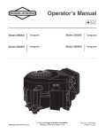
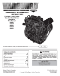
Operator’s Manual
Model 432447
522447
582447
BRIGGSandSTRATTON.com
Vanguard
Diesel
Model 588447
58A447
ECopyright Briggs & Stratton Corporation
Milwaukee, Wisconsin 53201 U.S.A.
Vanguard
Turbocharged Diesel
Form No. 277110-3/07
Printed in U.S.A.
TABLE OF CONTENTS
Safety . . . . . . . . . . . . . . . . . . . . . . . . . . . . . . . . . . . . . . .
Engine Information . . . . . . . . . . . . . . . . . . . . . . . . . . . .
Oil . . . . . . . . . . . . . . . . . . . . . . . . . . . . . . . . . . . . . . . . . . .
Fuel and Coolant . . . . . . . . . . . . . . . . . . . . . . . . . . . . .
Gauges . . . . . . . . . . . . . . . . . . . . . . . . . . . . . . . . . . . . . .
2
4
7
8
8
Starting and Stopping . . . . . . . . . . . . . . . . . . . . . . . . 8-9
Maintenance . . . . . . . . . . . . . . . . . . . . . . . . . . . . . . . . . 11
Adjustments . . . . . . . . . . . . . . . . . . . . . . . . . . . . . . . . . 16
Service & Storage . . . . . . . . . . . . . . . . . . . . . . . . . . . . 16
Warranty Information . . . . . . . . . . . . . . . . . . . . . . . . . 17
For replacement parts or technical assistance, record below the engine model, type, and code numbers along with the date of purchase.
These numbers are located on your engine (see the “Engine Information” page).
Date of purchase:
MM / DD / YYYY
Engine model:
Model:
Type:
BEFORE OPERATING ENGINE
THE OPERATING & MAINTENANCE INSTRUCTIONS CONTAIN SAFETY INFORMATION TO
• Make you aware of hazards associated with engines
• Inform you of the risk of injury associated with those
hazards, and
• Tell you how to avoid or reduce the risk of injury.
• Read entire Operating & Maintenance Instructions
AND the instructions for the equipment this engine
powers.*
• Failure to follow instructions could result in serious
injury or death.
*
Code:
Briggs & Stratton does not necessarily know what equipment this engine will power. For that reason, you should carefully
read and understand the operating instructions for the equipment on which your engine is placed.
(
HAZARD SYMBOLS AND MEANINGS
)
The safety alert symbol
is used to identify safety
information about hazards that can result in personal injury.
A signal word (DANGER, WARNING, or CAUTION) is used
with the alert symbol to indicate the likelihood and the
potential severity of injury. In addition, a hazard symbol may
be used to represent the type of hazard.
Fire
Explosion
Moving Parts
Hot Liquid
or Steam
DANGER indicates a hazard which, if not avoided,
will result in death or serious injury.
Toxic Fumes
WARNING indicates a hazard which, if not
avoided, could result in death or serious injury.
Hot Surface
Shock
THE INTERNATIONAL SYMBOLS USED ON
THE ENGINE OR IN THIS MANUAL INCLUDE:
CAUTION indicates a hazard which, if not avoided,
might result in minor or moderate injury.
Safety Alert
On Off
Oil
Stop
CAUTION, when used without the alert symbol,
indicates a situation that could result in damage to
the engine.
Read Operator’s
Fuel Shutoff
Manual
WARNING
The engine exhaust from this product
contains chemicals known to the State of
California to cause cancer, birth defects,
or other reproductive harm.
2
Choke
Fuel
SAFETY
WARNING
WARNING
Running engines produce heat. Engine
parts, especially turbocharger and
muffler, become extremely hot.
Fuel and its vapors are extremely flammable and explosive.
Fire or explosion can cause severe burns
or death.
Severe thermal burns can occur on
contact.
WHEN ADDING FUEL
Combustible debris, such as leaves,
grass, brush, etc. can catch fire.
• Turn engine OFF and let engine cool at least 2 minutes
before removing fuel cap.
• Fill fuel tank outdoors or in well-ventilated area.
• Do not overfill fuel tank. Fill tank to approximately 1-1/2
inches below top of neck to allow for fuel expansion.
• Keep fuel away from sparks, open flames, pilot lights, heat,
and other ignition sources.
• Check fuel lines, tank, cap, and fittings frequently for cracks
or leaks. Replace if necessary.
• Allow muffler, turbocharger, engine cylinder and fins to cool
before touching.
• Remove accumulated combustibles from muffler area and
cylinder area.
• Install and maintain in working order a spark arrester before
using equipment on forest-covered, grass-covered, brushcovered unimproved land. The state of California requires
this (Section 4442 of the California Public Resources
Code). Other states may have similar laws. Federal laws
apply on federal land.
WHEN STARTING ENGINE
• Make sure muffler, fuel cap and air cleaner are in place.
• If fuel spills, wipe it off before starting engine.
WARNING
WHEN OPERATING EQUIPMENT
• Do not tip engine or equipment at angle which causes fuel to
spill.
Rotating parts can contact or entangle
hands, feet, hair, clothing, or accessories.
WHEN TRANSPORTING EQUIPMENT
Traumatic amputation or severe laceration can result.
• Transport with fuel tank EMPTY or with fuel shut-off valve
OFF.
WHEN STORING FUEL OR EQUIPMENT WITH
FUEL IN TANK
•
•
•
•
• Store away from furnaces, stoves, water heaters or other
appliances that have pilot light or other ignition source
because they can ignite equipment with stored fuel or fuel
source.
WARNING
Explosion and fire could result.
• If there is natural or LP gas leakage in area, do not start
engine.
• Do not use pressurized starting fluids because vapors are
flammable.
3
Operate equipment with guards in place.
Keep hands and feet away from rotating parts.
Tie up long hair and remove jewelry.
Do not wear loose-fitting clothing, dangling drawstrings or
items that could become caught.
SAFETY
WARNING
WARNING
Engines give off carbon monoxide, an
odorless, colorless, poison gas.
Unintentional sparking can result in fire
or electric shock.
Breathing carbon monoxide can cause
nausea, fainting or death.
Unintentional start-up can result in
entanglement, traumatic amputation,
or laceration.
• Start and run engine outdoors.
• Do not start or run engine in enclosed area, even if doors
or windows are open.
BEFORE PERFORMING ADJUSTMENTS OR
REPAIRS
WARNING
• Disconnect battery at negative terminal.
Never remove radiator cap or radiator reservoir
cap while the engine is hot or running. Severe
thermal burns or injury can occur by escaping
steam or hot engine coolant.
WARNING
Briggs & Stratton does not approve or authorize the use of
these engines on 3-wheel All Terrain Vehicles (ATVs), motor
bikes, fun/recreational go-karts, aircraft products or vehicles
intended for use in competitive events. Use of these engines in
such applications could result in property damage, serious
injury (including paralysis), or even death.
• Stop engine and allow to cool before removing radiator or
reservoir cap.
• To remove reservoir cap after engine is cool, place a thick
cloth over cap and remove it slowly.
• To remove radiator cap after engine is cool, place a thick
cloth over cap and rotate it slowly counter-clockwise to
the first stop. Pressurized steam may emit from the cap,
stand back to avoid injury. Once all pressure is released,
rotate cap counter-clockwise while pushing down on cap
to remove.
ENGINE INFORMATION
TECHNICAL INFORMATION
Engine Power Rating Information
The gross power rating for individual gas engine models is labeled
in accordance with SAE (Society of Automotive Engineers) code
J1940 (Small Engine Power & Torque Rating Procedure), and rating performance has been obtained and corrected in accordance
with SAE J1995 (Revision 2002-05). Torque values are derived at
3060 RPM; horsepower values are derived at 3600 RPM. Actual
gross engine power will be lower and is affected by, among other
things, ambient operating conditions and engine-to-engine variability. Given both the wide array of products on which engines are
placed and the variety of environmental issues applicable to operating the equipment, the gas engine will not develop the rated
gross power when used in a given piece of power equipment (actual “on-site” or net power). This difference is due to a variety of factors including, but not limited to, accessories (air cleaner, exhaust,
charging, cooling, carburetor, fuel pump, etc.), application limitations, ambient operating conditions (temperature, humidity, altitude), and engine-to-engine variability. Due to manufacturing and
capacity limitations, Briggs & Stratton may substitute an engine of
higher rated power for this Series engine.
4
ENGINE INFORMATION
1
Diesel
2
13
6
12
7
3
11
1.
2.
3.
4.
5.
Thermostat
Oil filler cap
Electric starter
Oil pan
Alternator
Turbo-charged Diesel
6.
7.
8.
9.
10.
11.
12.
Injector nozzle
10
Glow plug
Oil drains
Oil filter
9
Dipstick
Injector pump
Engine Date Code
xxxxxxxxx
13. Engine Model & Type number
xxxxxx xxxx-xx
4
5
8
15
2
7
8
14
1
3
13
4
5
1.
2.
3.
4.
5.
6.
Thermostat
Oil filler cap
Turbocharger
Electric starter
Alternator
Oil pan
6
7.
8.
9.
10.
11.
12.
13.
14.
15.
Injector nozzle
Glow plug
12
Oil drains
Oil cooler
11
(if equipped)
Oil filter
Dipstick
Injector pump
Engine Date Code
xxxxxxxxx
Engine Model & Type number
xxxxxx xxxx-xx
10
9
GENERAL INFORMATION
This is a three cylinder, liquid cooled engine.
MODEL 522447
On mobile equipment, this engine will operate satisfactorily at any
angle at which operator and equipment can function safely.
Bore . . . . . . . . . . . . . . . . . . . . . . . . . . . . . . . . . 68 mm (2.68 in.)
Stroke . . . . . . . . . . . . . . . . . . . . . . . . . . . . . . . 78 mm (3.07 in.)
Displacement . . . . . . . . . . . . . . . . . . . . . . 850 cc (52.0 cu. in.)
MODEL 432447
MODEL 582447, 588447, 58A447
Bore . . . . . . . . . . . . . . . . . . . . . . . . . . . . . . . . . 68 mm (2.68 in.)
Stroke . . . . . . . . . . . . . . . . . . . . . . . . . . . . . . . 64 mm (2.52 in.)
Displacement . . . . . . . . . . . . . . . . . . . . . . 697 cc (42.5 cu. in.)
Bore . . . . . . . . . . . . . . . . . . . . . . . . . . . . . . . 72 mm (2.834 in.)
Stroke . . . . . . . . . . . . . . . . . . . . . . . . . . . . . . . 78 mm (3.07 in.)
Displacement . . . . . . . . . . . . . . . . . . . . . . 953 cc (58.1 cu. in.)
5
OIL
OIL CAPACITY
Oil capacity, including oil filter, is 3.3 liters (3.5 quarts).
TYPE OF OIL TO USE
SAE Viscosity Grades
• Use a high quality detergent oil classified “For Service CF, or
CF-4”.
• Do not use special additives with recommended oils.
• Do not mix oil with fuel.
• Choose a viscosity according to the table opposite.
*
CAUTION: This engine is shipped from Briggs &
Stratton without oil. Check oil level before starting
engine. If you start the engine without oil, the engine
will be damaged beyond repair and will not be
covered under warranty.
°F -30
°C -34
-10
10
32
50
70
90
110
-23
-12
0
10
21
32
43
STARTING TEMPERATURE RANGE ANTICIPATED BEFORE NEXT OIL CHANGE
*
A synthetic 5W-30 oil may be used.
CHECKING AND ADDING OIL
•
•
•
•
Note: After filling with or changing oil, start and run engine at
idle for 5 minutes. Shut engine off. Wait 3 minutes and check oil
level. Add oil, if required, to bring level to Full mark on dipstick.
Check oil level before starting the engine.
Check level daily, or after every eight (8) hours.
Keep oil level at FULL.
Do not overfill.
Bring oil
level to F
mark
on dipstick.
OIL FILL
[2]. Remove dipstick and wipe
with clean cloth.
[1]. Place equipment level.
Clean around oil fill.
[3]. Then replace dipstick, and
remove to check oil level.
[4]. If oil is required, remove dipstick to allow
proper venting and pour oil slowly. Fill to
FULL line on dipstick. Recheck.
CAUTION: When filling engine or adding oil.
To prevent engine damage upon
start-up, proper venting is necessary
when filling engine with oil or adding oil.
[5]. Replace dipstick firmly.
In addition to ensuring a level engine,
removing dipstick, and pouring oil
slowly, there must be clearance
between the oil fill device and the oil fill
hole in the valve cover as shown. This
clearance is necessary to permit
venting when filling, which prevents oil
from overrunning into breather.
6
Note
Clearance
Note
Clearance
FUEL
TYPE OF FUEL TO USE
CAUTION: Do not use kerosene or gasoline
instead of diesel fuel. Failure to observe this caution
will damage the engine.
• THIS ENGINE IS CERTIFIED TO OPERATE
ON DIESEL FUEL.
• Use clean, fresh, diesel fuel with a minimum of 40 cetane.
FUEL LEVEL
WARNING
• Keep fuel tank full.
• Do not overfill tank.
• Allow space in tank for fuel expansion.
• Fill fuel tank outdoors or in well-ventilated area,
away from sparks, open flames, pilot lights, heat,
and other ignition sources.
• If fuel spills, wait until it evaporates before starting
engine.
• Turn engine OFF and let engine cool at least 2
minutes before removing gas cap.
ADDING FUEL
[1]. Remove cap. Fill tank to approximately 1-1/2 inches
below top of neck to allow for fuel expansion. Be careful
not to overfill.
[2]. Replace cap before starting.
[3]. Check for fuel leaks at fuel filter, injector pump, fuel
pipes, etc.
COOLANT
WARNING
SPECIFICATIONS
• Do not touch radiator or open
radiator cap, or open reservoir
when engine is hot or running.
• Allow engine to cool before
changing or adding coolant.
• This engine is water cooled.
• A 50/50% mixture is required of phosphate-free antifreeze and
tap water for heat dissipation, rust resistance and lubrication.
CHANGING & ADDING COOLANT
• Fill radiator to bottom of fill cap seat and between FULL and LOW
in reservoir, if so equipped.
GAUGES
TYPICAL GAUGES (If Equipped)
FUEL GAUGE
To minimize condensation, keep fuel
tank full.
COOLANT TEMPERATURE GAUGE
Indicates coolant temperature
when the starter switch is ON.
Normal range 80°-90° C
(175°-195° F).
Dangerous range above 105° C
(220° F).
FUEL SHUT-OFF
Open valve before starting
engine.
HOUR METER
Indicates the total number of hours the
engine has been run.
ON
POSITION
CAUTION: To prevent leaking, close fuel shutoff valve when engine is transported.
7
GAUGES
TYPICAL PANEL LIGHTS (If Equipped)
WARNING LIGHTS (Typical)
Fuel filter light
The fuel filter light comes on when enough water collects in
the fuel filter, but should be out when the water is drained.
If fuel filter warning light comes on while engine is running, stop
engine and drain water from fuel filter.
Engine oil pressure light
The engine oil pressure light comes on when the starter
switch is turned to the ON position and should be out while
engine is running. If oil pressure light comes on while engine is
running, stop engine immediately. Check oil level or electrical
system.
Charge light
The charge light comes on when the starter switch is turned to
the ON position, but should be out while engine is running.
If charge light comes on while engine is running, check electrical
system.
If charge light does not come on when starter switch is turned to
the ON position, check fuse or bulb.
X
Ignition light
The ignition light comes on when the starter switch is turned to
the ON position, and should be out while engine is running.
Temperature light
If temperature light comes on, engine is overheating. Check:
S coolant level;
S debris on radiator or any restriction to air flow.
Heat or glow light
The heat or glow light comes on when the starter switch is
turned to HEAT or GLOW (ON if no HEAT or GLOW position),
but should be out while engine is running.
See an Authorized Briggs & Stratton 3/LC Service Dealer if
necessary for operation repair.
STARTING
STARTING IN COLD WEATHER:
(below -10° C or 14° F)
♦ Use correct type of oil for expected starting
temperature. (See Oil.)
♦ Remove external equipment/engine loads. (See
equipment operating instructions.)
♦ Open fuel shut-off valve, if equipped, before starting
engine.
♦ Start with throttle control in FAST position.
♦ Do not use fuel left over from summer. Use fresh fuel.
♦ Allow engine to warm up several seconds to several
minutes, depending on outside temperature.
CAUTION: Before starting engine for
the first time, charge battery as the
equipment manufacturer recommends.
Failure to do so, may cause damage to
the engine.
WARNING
• The manufacturer of equipment on which
this engine is installed specifies top speed at
which engine will be operated. DO NOT
EXCEED this speed.
WARNING
• Do not use pressurized starting fluids.
• Vapors are flammable.
• Keep hands and feet clear of rotating
machinery.
8
STARTING & STOPPING
TO START ENGINE
[3]. Insert key into starter
switch at OFF position.
Turn key to ON or HEAT.
(GLOW light comes on
indicating glow plugs are
preheating combustion
chamber.)
Typical throttle control
[1]. Insert key into starter
switch at OFF position.
[2]. Move throttle control
to SLOW.
Typical starter switch
CAUTION:
To prolong starter life,
use short starting cycles,
not to exceed 30 secs./
min.
Typical starter switch
[4]. When GLOW light goes out,
turn key to START.
CAUTION:
DO NOT accelerate or race a
cold engine. Failure to observe
this caution may lead to engine
damage.
Typical starter switch
Extended cranking can
damage starter motor.
[5]. When engine starts, release key,
which will return to ON position.
[6]. Move throttle control to SLOW
(if in FAST for cold starting
instructions).
[7]. Allow engine to warm up a few
minutes before applying load.
Typical throttle control
TO STOP ENGINE
CAUTION:
FOR TURBOCHARGER-EQUIPPED
ENGINE.
Typical throttle control
Typical starter switch
[1]. Move throttle to SLOW.
Allow engine to run for
short time to cool down.
[2]. Turn key to OFF.
Always remove key and
store out of reach of children.
9
After operating engine at full load, allow
engine to idle for one minute before shutting it
off. Failure to observe this caution may lead
to turbocharger malfunction.
MAINTENANCE
REGULAR MAINTENANCE WILL IMPROVE THE PERFORMANCE AND EXTEND THE LIFE OF THE ENGINE. MORE
FREQUENT SERVICE IS REQUIRED WHEN OPERATING IN ADVERSE CONDITIONS.
See any Authorized Briggs & Stratton 3/LC Dealer for service. Use only genuine Briggs & Stratton parts. Other parts may not
perform as well, may damage the engine, and may result in injury. In addition, use of other parts may void your warranty.
DAILY CHECKS
Task
Perform
task at
hourly or
calendar
interval.
Check oil
level
Check for
oil leaks
OIL
Before starting engine, check oil for correct level.
See page 6 of this manual for instructions on checking
and adding oil.
4
CAUTION:
4
Change oil
and oil filter
Check
coolant
4*
4***
CONTROL PARTS
4
Change
coolant
4
Service air
cleaner
4*
WARNING
4**
Check
valve
clearance
Change
fuel filter
element
To assure smooth operation, keep injector pump linkage, springs and controls free of debris. Linkage should
move freely. Depending on use, this may need to be
performed more often.
4
Check fan
belt
Check
battery
electrolyte
Used oil is a hazardous waste product. Dispose of
used oil properly. Do not discard with household
waste. Check with your local authorities, service
center, or dealer for safe disposal/recycling facilities.
4
Engine parts should be kept
clean to reduce the risk of
overheating and ignition of
accumulated debris.
CAUTION: Do not use water to clean engine
parts. Water could contaminate fuel system. Use a
brush or dry cloth.
4
MUFFLER
4****
WARNING
* Perform first maintenance operation after 50
hours. All subsequent maintenance performed at
this interval, unless specified. Service more often
when operating under heavy load or in high
temperatures.
** Replace after every 600 hours of operation.
Service more often when operating under heavy
load or in high temperature.
*** Perform annually if operated less than 100 hours.
**** Follow manufacturer’s maintenance schedule if
non-Briggs & Stratton approved part is used.
10
Before running engine, clean
muffler and manifold areas to
remove all grass and combustible debris.
Depending on use, this may
need to be performed more
often.
MAINTENANCE
DAILY CHECKS continued
COOLANT
WARNING
Coolant level should be between FULL and LOW when
engine is cold. If reservoir is dry, it must be filled along with
radiator.
Check coolant level when engine is cold.
If engine is warm DO NOT remove radiator cap.
Normal water temperature
gauge should read between
WARNING
175° and 195° F (80° and 90° C)
when engine is running.
If water temperature rises
above 220° F (105° C), idle
engine down for a while. Then stop engine. Once engine
is cooled, check coolant level, fan belt tension and
clogged radiator fins.
Never remove radiator cap or radiator reservoir
cap while the engine is hot or running. Severe
thermal burns or injury can occur by escaping
steam or hot engine coolant.
• Stop engine and allow to cool before removing radiator or
reservoir cap.
• To remove reservoir cap after engine is cool, place a thick
cloth over cap and remove it slowly.
• To remove radiator cap after engine is cool, place a thick
cloth over cap and rotate it slowly counter-clockwise to
the first stop. Pressurized steam may emit from the cap,
stand back to avoid injury. Once all pressure is released,
rotate cap counter-clockwise while pushing down on cap
to remove.
REGULAR MAINTENANCE
WARNING
CHANGING OIL
[1]. Place engine level.
[2]. Disconnect battery at negative terminal.
[3]. With engine OFF but still warm remove oil drain
plug and drain oil into appropriate receptacle.
• Disconnect battery at negative terminal.
[4]. Change the oil filter. See “Changing Oil Filter”.
[5]. Reinstall drain plug and torque to 352 kg-cm
(25.5 ft-lb).
[6]. Refill engine with new oil. Fill to FULL mark on
dipstick with new oil. Replace oil cap.
Caution: Do not overfill.
[7]. Start and run engine at idle for 5 minutes.
[8]. Stop engine, and wait 3 minutes. Then re-check oil
level.
OIL FILTER
[9]. If required, add oil to bring level to F mark on
dipstick.
OIL DRAIN PLUG
OIL DRAIN PLUG
[10]. Check for leaks.
Oil drain/Oil filter
11
MAINTENANCE
REGULAR MAINTENANCE continued
WARNING
CHANGING OIL FILTER
[1]. Perform this maintenance during oil change maintenance. Drain engine oil as described for oil
change, and remove oil filter.
• Disconnect battery at
negative terminal.
[2]. Before installing new filter, apply to filter gasket
fresh, clean oil.
[3]. Screw filter on by hand until gasket contacts oil
filter adapter. Tighten 1/2 to 3/4 turn more.
[4]. Add fresh oil. Follow steps as described for oil
change.
OIL FILTER
[5]. Check for oil leaks around filter.
OIL DRAIN PLUG
OIL DRAIN PLUG
Oil drain/Oil filter
AIR CLEANER
Note: Air cleaner may be supplied by equipment manufacturer.
Cartridge
To clean cartridge, gently tap on end with handle of
screwdriver. (Replace cartridge if very dirty or damaged.)
AIR
CLEANER
BODY
CAUTION: Do not use pressurized air or solvents
to clean cartridge. Pressurized air can damage
cartridge; solvents will dissolve cartridge.
CARTRIDGE
[1]. Unlock clamps and remove cover.
COVER
[2]. Remove cartridge from air cleaner body.
[3]. Carefully clean out air cleaner cover.
CLAMPS
[4]. Install cartridge in body.
[5]. Install cover and lock clamps.
12
MAINTENANCE
FUEL FILTER
If the fuel filter warning light comes on while engine is
running, stop engine and drain water from fuel filter.
To drain water:
WARNING
[1]. Stop engine.
[2]. Place a drain pan under fuel filter and loosen drain
plug approximately 1 turn.
• Disconnect battery at
negative terminal.
PRIMING
PUMP
[3]. Water should drain. If necessary, operate priming
pump to drain water, but only until fuel flows from filter.
O-RING
[4]. Tighten drain plug.
[5]. Start engine. Ensure warning light goes out. Check for
leaks.
To replace fuel filter:
[1]. Disconnect sensor wire. Remove drain plug and
discard O-ring.
FUEL
FILTER
DRAIN
PLUG
[2]. Remove fuel filter with filter wrench.
[3]. Screw new filter on by hand until gasket contacts
housing. Then tighten 1/3 turn more.
SENSOR
WIRE
[4]. Install drain plug with new O-Ring. Connect sensor
wire.
[5]. Activate primer pump until resistance is felt.
Drain/replace fuel filter
[6]. Start engine and check for leaks.
VALVE CLEARANCE
With No. 1 piston at TDC of compression stroke, check valve
clearances for cylinders shown in chart below. Rotate crankshaft 360° clockwise to check remaining valves. Adjust in
same order, if required.
Note: If engine is running normally, this check and adjustment
may be omitted.
Piston Position
Cylinder
No. 1 piston at TDC, of compres
compression stroke
Rotate Crankshaft 360° clockwise
[1]. Loosen adjusting lock nut.
1
Int
D
Exh
D
Int
2
3
D
D
D
D
Exh
[2]. Using a wrench to hold adjusting lock nut, adjust with
screwdriver. Determine clearance using a feeler gauge.
[3]. While holding screw driver in place, torque adjusting
lock nut.
Valve clearances (cold):
Int
SCREW
DRIVER
0.2 mm (0.008 in.)
WRENCH
FEELER
GAUGE
Exh 0.2 mm (0.008 in.)
Adjusting lock nut torque: 110 kg-cm (95 in. lbs.)
Check valve cover gasket for leakage. Replace if required.
Torque valve cover nuts to 55 kg-cm (48 in. lbs.)
Valve clearance adjustment
13
MAINTENANCE
FAN BELT
♦ Check condition of fan belt.
♦ Replace if damaged or worn.
To check for correct fan belt tension
BELT
When 10 kg (22 lbs.) of force is pressed at center of span
between fan and alternator, there should be 10 to 12 mm
(3/8 − 1/2 in.) of belt movement.
10 − 12 mm
(3/8 − 1/2 Inch)
BELT MOVEMENT
To adjust for correct tension
[1]. Loosen the 2 bolts ( A and B ).
BELT
HANDLE
[2]. Place a handle (or similar object) between the
alternator and engine cylinder block. Then move the
alternator towards the outside of the engine, until the
fan belt deflection conforms to the specified value.
Specified fan belt deflection:
10 to 12 mm / 10 kg (3/8 to 1/2 in. / 22 lbs.)
A
[3]. Temporarily tighten the 2 bolts ( A and B ) to fix the
alternator. Then remove the handle. Check fan belt
deflection. If it is within specifications, permanently
tighten the 2 bolts ( A and B ) as given below. If not,
repeat the above adjustment procedure.
Specified tightening torque:
A : 195 kg-cm (170 in-lbs)
B : 622 kg-cm (45 ft-lbs)
Check the fan belt deflection again.
10 − 12 mm
(3/8 − 1/2 Inch)
BELT MOVEMENT
SPARK ARRESTOR
♦ If engine muffler is equipped with spark arrestor screen
assembly, remove for cleaning and inspection every 50
hours. Replace if damaged.
14
B
ADJUSTMENTS
LOCK NUT
IDLE
SPEED
SCREW
SPEED
CONTROL
LEVER
TO ADJUST THROTTLE CONTROL
[1]. Move equipment throttle control in SLOW or IDLE
position.
[2]. If lever does not contact idle speed screw, loosen casing
clamp screw.
[3]. Adjust throttle control cable to allow speed control lever
to contact idle speed screw.
Ì
Ì
[4]. Tighten casing clamp screw.
TO ADJUST IDLE SPEED
[1]. Move equipment throttle control in SLOW or IDLE
position.
Injector pump
[2]. Loosen lock nut.
CONTROL ADJUSTMENTS
[3]. Adjust idle speed screw to obtain equipment manufacturer’s specified idle speed.
If engine is hard to start or acceleration is uneven, check
control operation and adjust if required as described
below:
[4]. Tighten lock nut.
[5]. Re-adjust throttle control if required.
15
SERVICE
PARTIAL LIST OF GENUINE BRIGGS & STRATTON PARTS
Part
Part No.
Oil . . . . . . . . . . . . . . . . . . . . . . . . . . . . . . . . . . . . . . . . . . 100028
Oil filter . . . . . . . . . . . . . . . . . . . . . . . . . . . . . . . . . . . . . 820314
Air filter . . . . . . . . . . . . . . . . . . . . . . . . . . . . . . . . . . . . . 820263
Fuel filter element . . . . . . . . . . . . . . . . . . . . . . . . . . . . 820311
SERVICE
See an Authorized Briggs & Stratton 3/LC Service Dealer.
Each one carries a stock of Genuine Briggs & Stratton 3/LC
Parts and is equipped with special service tools. Only dealers
advertising as Authorized Briggs & Stratton 3/LC Service
Dealers are required to meet Briggs & Stratton standards.
You may locate your nearest Authorized Briggs & Stratton
3/LC Service Dealer by calling 1-800-233-3723.
When you purchase equipment powered by a Briggs &
Stratton engine, you are assured of highly skilled, reliable
service at any Authorized
Service Dealers worldwide.
Look for these signs wherever Briggs & Stratton service is
offered.
The illustrated shop manual shown here
includes common specifications and
detailed information covering adjustment, tune-up and repair of Vanguard
three cylinder, 4 cycle engines. It is
available from any Authorized Briggs &
Stratton Service Dealer.
Part No. MS-1055
STORAGE
STORAGE
Engines stored over 30 days need special attention.
[1]. While engine is still warm, change oil.
[2]. Remove glow plugs and pour about 3 cc of engine oil into
each cylinder. Replace glow plugs and crank slowly to
distribute oil.
[3]. Clean engine of surface debris, chaff or grass.
[4].
16
WARNING
Store in a clean, dry area. Do
not store in same area as a
stove, furnace, water heater, or
other appliance that uses a pilot
light or has a device that can
create a spark.
For Model 432447, 522447 & 582447
Briggs & Stratton Corporation (B&S), the California Air Resources Board (CARB)
and the United States Environmental Protection Agency (U.S. EPA)
Emissions Control System Warranty Statement (Owner’s Defect Warranty Rights and Obligations)
EMISSIONS CONTROL WARRANTY COVERAGE IS APPLICABLE TO
CERTIFIED MODEL YEAR 2001 AND LATER ENGINES, WHICH ARE PURCHASED AND USED IN CALIFORNIA, AND TO CERTIFIED MODEL YEAR
2001 AND LATER ENGINES, WHICH ARE PURCHASED AND USED ELSEWHERE IN THE UNITED STATES.
California and United States Emissions Control Defects Warranty Statement
provided there has been no abuse, neglect or improper maintenance of your
Non-road Compression-ignition engine.
Your emissions control system includes parts such as the air cleaner, ignition system and muffler. Also included may be connectors and other emissions related assemblies.
Where a warrantable condition exists, B&S will repair your Non-road Compression-ignition engine at no cost to you including diagnosis, parts and
labor.
The California Air Resources Board (CARB), U.S. EPA and B&S are pleased
to explain the Emissions Control System Warranty on your model year 2001
and later Non-road Compression-ignition engine. In California, new Non-road
Compression-ignition engines must be designed, built and equipped to meet
the State’s stringent anti-smog standards. Elsewhere in the United States, new
Non-road Compression-ignition engines certified for model year 2001 and later, must meet similar standards set forth by the U.S. EPA. B&S must warrant
the emissions control system on your engine for the period of time listed below,
Briggs & Stratton Corporation Emissions Control Defects Warranty Coverage
Non-road Compression-ignition engines are warranted relative to emissions
control parts defects for a period of 1500 hours or two years, whichever occurs first, subject to provisions set forth below. If any covered part on your
Non-road Compression-ignition engine is defective, the part will be repaired
or replaced by B&S.
Owner’s Warranty Responsibilities
pression-ignition engine or a part has failed due to abuse, neglect, improper
maintenance or unapproved modifications.
You are responsible for presenting your Non-road Compression-ignition engine to an Authorized B&S Service Dealer as soon as a problem exists. The
undisputed warranty repairs should be completed in a reasonable amount of
time, not to exceed 30 days.
If you have any questions regarding your warranty rights and responsibilities, you should contact a B&S Service Representative at 1-800-233-3723.
As the Non-road Compression-ignition engine owner, you are responsible for
the performance of the required maintenance listed in your Operating &
Maintenance Instructions. B&S recommends that you retain all your receipts covering maintenance on your Non-road Compression-ignition engine, but B&S cannot deny warranty solely for the lack of receipts or for your
failure to ensure the performance of all scheduled maintenance.
As the Non-road Compression-ignition engine owner, you should however be
aware that B&S may deny you warranty coverage if your Non-road Com-
Briggs & Stratton Corporation Emissions Control Defects Warranty Provisions
3. No Charge
Repair or replacement of any Warranted Part will be performed at no
charge to the owner, including diagnostic labor which leads to the determination that a Warranted Part is defective, if the diagnostic work is performed at an Authorized B&S Service Dealer. For emissions warranty
service, contact your nearest Authorized B&S Service Dealer as listed in
the “Yellow Pages” under “Lawn Mowers,” “Engines, Gasoline,” “Gasoline Engines” or similar category.
The following are specific provisions relative to your Emissions Control Defects
Warranty Coverage. It is in addition to the B&S engine warranty for non-regulated
engines found in the Operating & Maintenance Instructions.
1. Warranted Parts
Coverage under this warranty extends only to the parts listed below (the
emissions control systems parts) to the extent these parts were present
on the engine purchased.
a. Fuel Metering System
• Injection Pump with feed pump
• Injection nozzle
• Fuel Filter
b. Air Induction System
• Air cleaner
• Intake manifold
c. Ignition System
• Glow plug
d. Exhaust System
• Exhaust manifold
e. Miscellaneous Items Used in Above Systems
• Vacuum, temperature, position, time sensitive valves and
switches
• Electronic Controls
• Connectors and assemblies
• Hoses
2. Length of Coverage
B&S warrants to the initial owner and each subsequent purchaser that
the Warranted Parts shall be free from defects in materials and workmanship which caused the failure of the Warranted Parts for a period of 1500
hours or two years, whichever occurs first, from the date the engine is
delivered to a retail purchaser.
4. Claims and Coverage Exclusions
Warranty claims shall be filed in accordance with the provisions of the
B&S Engine Warranty Policy. Warranty coverage shall be excluded for
failures of Warranted Parts which are not original B&S parts or because
of abuse, neglect or improper maintenance as set forth in the B&S Engine Warranty Policy. B&S is not liable to cover failures of Warranted
Parts caused by the use of add-on, non-original, or modified parts.
5. Maintenance
Any Warranted Part which is not scheduled for replacement as required
maintenance or which is scheduled only for regular inspection to the effect of “repair or replace as necessary” shall be warranted as to defects
for the warranty period. Any Warranted Part which is scheduled for
replacement as required maintenance shall be warranted as to defects
only for the period of time up to the first scheduled replacement for that
part. Any replacement part that is equivalent in performance and durability may be used in the performance of any maintenance or repairs. The
owner is responsible for the performance of all required maintenance, as
defined in the B&S Operating & Maintenance Instructions.
6. Consequential Coverage
Coverage hereunder shall extend to the failure of any engine components caused by the failure of any Warranted Part still under warranty.
17
For Model 588447 & 58A447
Briggs & Stratton Corporation (B&S), the California Air Resources Board (CARB)
and the United States Environmental Protection Agency (U.S. EPA)
Emissions Control System Warranty Statement (Owner’s Defect Warranty Rights and Obligations)
EMISSIONS CONTROL WARRANTY COVERAGE IS APPLICABLE TO CERTIFIED MODEL 2001 AND LATER ENGINES, WHICH ARE PURCHASED
AND USED IN CALIFORNIA, AND TO CERTIFIED MODEL YEAR 2001 AND
LATER ENGINES, WHICH ARE PURCHASED AND USED ELSEWHERE IN
THE UNITED STATES.
California, and United States Emissions Control Defects Warranty Statement
The California Air Resources Board (CARB), U.S. EPA and B&S are pleased to
explain the Emissions Control System Warranty on your model year 2001 and
later Non-road Compression-ignition engine. In California, new Non-road Compression-ignition engines must be designed, built and equipped to meet the
State’s stringent anti-smog standards. Elsewhere in the United States, new Nonroad Compression-ignition engines certified for model year 2001 and later, must
meet similar standards set forth by the U.S. EPA. B&S must warrant the emissions control system on your engine for the period of time listed below, provided
there has been no abuse, neglect or improper maintenance of your Non-road
Compression-ignition engine.
Your emissions control system includes parts such as the air cleaner, ignition
system and muffler. Also included may be connectors and other emissions related assemblies.
Where a warrantable condition exists, B&S will repair your Non-road Compression-ignition engine at no cost to you including diagnosis, parts and labor.
Briggs & Stratton Corporation Emissions Control Defects Warranty Coverage
Small off-road engines are warranted relative to emissions control parts defects for a period of 3,000 hours or five years, subject to provisions set forth
below.
If any covered part on your Non-road Compression-ignition engine is defective, the part will be repaired or replaced by B&S.
Owner’s Warranty Responsibilities
As the Non-road Compression-ignition engine owner, you are responsible for
the performance of the required maintenance listed in your Operating & Maintenance Instructions. B&S recommends that you retain all your receipts covering maintenance on your Non-road Compression-ignition engine, but B&S
cannot deny warranty solely for the lack of receipts or for your failure to ensure
the performance of all scheduled maintenance.
sion-ignition engine or a part has failed due to abuse, neglect, improper maintenance or unapproved modifications.
You are responsible for presenting your Non-road Compression-ignition engine to an Authorized B&S Service Dealer as soon as a problem exists. The
undisputed warranty repairs should be completed in a reasonable amount of
time, not to exceed 30 days.
If you have any questions regarding your warranty rights and responsibilities,
you should contact a B&S Service Representative at 1-800-233-3723.
As the Non-road Compression-ignition engine owner, you should however be
aware that B&S may deny you warranty coverage if your Non-road Compres-
Briggs & Stratton Corporation Emissions Control Defects Warranty Provisions
2. Length of Coverage
The following are specific provisions relative to your Emissions Control Defects
Warranty Coverage. It is in addition to the B&S engine warranty for non-regulated
engines found in the Operating & Maintenance Instructions.
B&S warrants to the initial owner and each subsequent purchaser that the
Warranted Parts shall be free from defects in materials and workmanship
which caused the failure of the Warranted Parts for a period of 3,000 hours
or five years from the date the engine is delivered to a retail purchaser.
1. Warranted Parts
Coverage under this warranty extends only to the parts listed below (the
emissions control systems parts) to the extent these parts were present on
the engine purchased.
3. No Charge
Repair or replacement of any Warranted Part will be performed at no
charge to the owner, including diagnostic labor which leads to the determination that a Warranted Part is defective, if the diagnostic work is performed at an Authorized B&S Service Dealer. For emissions warranty service, contact your nearest Authorized B&S Service Dealer as listed in the
“Yellow Pages” under “Lawn Mowers,” “Engines, Gasoline,” “Gasoline Engines” or similar category.
a. Fuel Metering System
• Injection pump with feed pump
• Injection nozzle
• Fuel Filter
4. Claims and Coverage Exclusions
b. Air Induction System
Warranty claims shall be filed in accordance with the provisions of the B&S
Engine Warranty Policy. Warranty coverage shall be excluded for failures
of Warranted Parts which are not original B&S parts or because of abuse,
neglect or improper maintenance as set forth in the B&S Engine Warranty
Policy. B&S is not liable to cover failures of Warranted Parts caused by the
use of add-on, non-original, or modified parts.
• Air cleaner
• Intake manifold
c. Ignition System
• Glow plug
5. Maintenance
Any Warranted Part which is not scheduled for replacement as required
maintenance or which is scheduled only for regular inspection to the effect
of “repair or replace as necessary” shall be warranted as to defects for the
warranty period. Any Warranted Part which is scheduled for replacement
as required maintenance shall be warranted as to defects only for the
period of time up to the first scheduled replacement for that part. Any replacement part that is equivalent in performance and durability may be
used in the performance of any maintenance or repairs. The owner is responsible for the performance of all required maintenance, as defined in
the B&S Operating & Maintenance Instructions.
d. Exhaust System
• Exhaust manifold
• Turbocharger
e. Miscellaneous Items Used in Above Systems
• Vacuum, temperature, position, time sensitive valves and switches
• Electronic Controls
6. Consequential Coverage
• Connectors and assemblies
Coverage hereunder shall extend to the failure of any engine components
caused by the failure of any Warranted Part still under warranty.
• Hoses
18
BRIGGS & STRATTON 3/LC ENGINE OWNER WARRANTY POLICY
Effective January 1, 2006 replaces all undated Warranties and all Warranties dated before January 1, 2006
LIMITED WARRANTY
Briggs & Stratton Corporation (B&S) will repair or replace, free of charge, any part(s) of the engine that is defective in material or workmanship or both.
Transportation charges on parts submitted for repair or replacement under this warranty must be borne by purchaser. This warranty is effective for the
time periods and subject to the conditions stated below. For warranty service, find the nearest Authorized Briggs & Stratton 3/LC Service Dealer in
our dealer locator map at www.briggsandstratton.com, or by calling 1-800-233-3723, or as listed in the ‘Yellow Pages™’.
THERE IS NO OTHER EXPRESS WARRANTY. IMPLIED WARRANTIES, INCLUDING THOSE OF MERCHANTABILITY AND FITNESS FOR A
PARTICULAR PURPOSE, ARE LIMITED TO ONE YEAR FROM PURCHASE, OR TO THE EXTENT PERMITTED BY LAW ANY AND ALL IMPLIED
WARRANTIES ARE EXCLUDED. LIABILITY FOR INCIDENTAL OR CONSEQUENTIAL DAMAGES ARE EXCLUDED TO THE EXTENT EXCLUSION
IS PERMITTED BY LAW. Some states or countries do not allow limitations on how long an implied warranty lasts, and some states or countries do not
allow the exclusion or limitation of incidental or consequential damages, so the above limitation and exclusion may not apply to you. This warranty gives
you specific legal rights and you may also have other rights which vary from state to state and country to country.
OUR PRODUCT
VANGUARDE
3/LC Engine
Major Parts Warranty*
Parts & Labor*
WARRANTY PERIOD
*
3 years
2 years
Consumer and Commercial Use
2 years
Note the following special warranty periods: For purposes of this warranty policy, Parts and Labor coverage is 2 years. Major parts only
coverage is extended to through the third year of operation. Major Parts Warranty (M.P.W.) covers but is not limited to or exclusive to cylinder
block, cylinder head, crankshaft, camshaft, gears, pistons, rods, flywheel, flywheel housing, oil pump, fan, pulleys, mechanical governor,
intake manifold, oil pan. M.P.W. does not cover and is not limited to piston rings, replaceable bearings, water pump, any electrical component,
valve train components, accessory parts, seals, gaskets, carburetors, exhaust manifold, hoses, all fuel system components, injectors,
injection pump, turbocharger, muffler, any filters, radiator, thermostat, spark plugs, glow plugs, fuel transfer pumps. The warranty period begins
on the date of purchase by the first retail consumer or commercial end user, and continues for the period of time stated in the table above.
NO WARRANTY REGISTRATION IS NECESSARY TO OBTAIN WARRANTY ON B&S ENGINES. SAVE YOUR PROOF OF PURCHASE
RECEIPT. IF YOU DO NOT PROVIDE PROOF OF THE INITIAL PURCHASE DATE AT THE TIME WARRANTY SERVICE IS REQUESTED,
THE MANUFACTURING DATE OF THE PRODUCT WILL BE USED TO DETERMINE THE WARRANTY PERIOD.
ABOUT YOUR ENGINE WARRANTY
B&S welcomes warranty repair and apologizes to you for being
inconvenienced. Any Authorized Briggs & Stratton 3/LC Service
Dealer may perform warranty repairs. Most warranty repairs are
handled routinely, but sometimes requests for warranty service
may not be appropriate. For example, warranty would not apply
if engine damage occurred because of misuse, lack of routine
maintenance, shipping, handling, warehousing or improper
installation. Similarly, warranty is void if the serial number of the
engine has been removed or the engine has been altered or
modified.
If a customer differs with the decision of the Service Dealer, an
investigation will be made to determine whether the warranty
applies. Ask the Service Dealer to submit all supporting facts to
the Distributor or the Factory for review. If the Distributor or the
Factory decides that the claim is justified, the customer will be
fully reimbursed for those items that are defective. To avoid
misunderstanding which might occur between the customer and
the Dealer, listed below are some of the causes of engine failure
that the warranty does not cover.
Normal wear:
Engines, like all mechanical devices, need periodic parts service
and replacement to perform well. Warranty will not cover repair
when normal use has exhausted the life of a part or an engine.
Improper maintenance:
The life of an engine depends upon the conditions under which it
operates, and the care it receives. Some applications, such as
tillers, pumps and rotary mowers, are very often used in dusty or
dirty conditions, which can cause what appears to be premature
wear. Such wear, when caused by dirt, dust, spark plug cleaning
grit, or other abrasive material that has entered the engine
because of improper maintenance, is not covered by warranty.
This warranty covers engine related defective material
and/or workmanship only, and not replacement or refund of
the equipment to which the engine may be mounted. Nor
does the warranty extend to repairs required because of:
1. Engines that are not properly applied to equipment. It is
strongly recommended that the factory be contacted prior
to applying a B&S 3/LC engine to equipment that did not
originally use a B&S 3/LC engine.
2. PROBLEMS CAUSED BY PARTS THAT ARE NOT
ORIGINAL BRIGGS & STRATTON PARTS.
3. Equipment controls or installations that prevent starting,
cause unsatisfactory engine performance, or shorten
engine life. (Contact equipment manufacturer.)
4. Leaking carburetors, clogged fuel pipes or injectors,
sticking valves, contaminated injection pumps, or other
damage, caused by using contaminated or stale fuel. Use
clean, fresh fuel (lead free gasoline, diesel fuel) and Briggs
& Stratton fuel stabilizer, Part No. 5041.
5. Parts which are scored or broken because an engine was
operated with insufficient or contaminated lubricating oil,
or an incorrect grade of lubricating oil (check oil level daily
or after every 8 hours of operation. Refill when necessary
and change oil and oil filter at recommended intervals.)
OIL GARD may not shut down running engine. Engine
damage may occur if oil level is not properly maintained.
Read Operating & Maintenance Instructions.
19
6.
Repair or adjustment of associated parts or assemblies
such as clutches, transmissions, remote controls, etc.,
which are not manufactured by B&S.
7. Damage or wear to parts caused by dirt, which entered the
engine because of improper air cleaner maintenance,
re-assembly, or use of a non-original air cleaner element
or cartridge. (At recommended intervals, replace
cartridge.) Read Operating & Maintenance Instructions.
8. Parts damaged by over-speeding, or overheating caused
by grass, debris, or dirt, which plugs, clogs radiator or air
cooling access openings, or damage caused by operating
the engine in a confined area without sufficient ventilation.
Engine damage caused by not using accurate mix of
anti-freeze and tap water, or water entering the engine due
to any cause.
9. Engine or equipment parts broken by excessive vibration
caused by a loose engine mounting, loose cutter blades,
unbalanced blades or loose or unbalanced impellers,
improper attachment of equipment to engine crankshaft,
over-speeding or other abuse in operation.
10. Routine tune-up or adjustment of the engine.
11. Engine or engine component failure, i.e., combustion
chamber, valves, valve seats, valve guides, or burned
starter motor windings, caused by the use of alternate
fuels such as, liquified petroleum, natural gas, altered
gasolines, etc.
Warranty is available only through service dealers which
have been authorized by Briggs & Stratton. Locate your
nearest Authorized B&S 3/LC Service Dealer through our
dealer locater map on www.briggsandstratton.com.