1
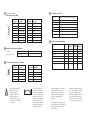
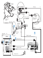
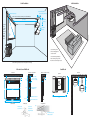
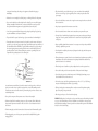
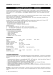
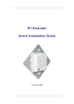
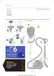
Ensemble
HD
Home Cinema System
™
Ensemble HD Schematic
A
Pin
Assignment
Description
1
Left Ch +
9
N/C
2
Right Ch +
10
Common Gnd
3
Center Ch +
11
N/C
4
Common Gnd
12
N/C
5
N/C
13
Surr Left +
6
Common Gnd
14
Surr Right +
7
Common Gnd
15
Sub +
8
Common Gnd
Shell
Chassis safety ground
15
5
6
1
6
B
C
D
Interface Specifications
Audio Input Connector (DB15)
Pin
Assignment
Description
Motorized Screen Control
AC Input
Main Power (3 wire IEC style, UL/CSA approved)
AC Output
To Projector (3 wire IEC style, UL/CSA approved)
Screen Motor
To Screen Motor (3 wire Molex style)
Projector Control
To Projector (DB15 connector, RS-232 I/F)
AV Remote
To AV Controller (1/8” stereo minijack)
Trigger
Sub Woofer Output Connector (RCA Style)
E
Power LED
To AV Controller (1/8” minijack)
I/R Emitter
To IR receiver/emitter in Ctr spkr (5 pin connector)
Cables Color, Length and Quantity
Item
Color
Length (m)
Pre-Wire
Length (m)
Quantity
10-Conductor Speaker Cable
Blue
10
10
1
Pin: Signal
Input Voltage (Sub Channel)
Output Voltage (Sub Out)
4-Conductor Speaker Cable
Blue
7
7
1
Shield: Signal Ground
.85 – 1.25V rms
1.7V – 2.5V rms (6dB Gain Circuit)
HDMI Kit
Black
7, 10
10
2
RS-232 Control Cable
Red
7
7
1
IR Data Cable
Red
10
10
1
AC Main Power Jumpers
Green
N/A
1
2
HD15 Cable
N/A
3
N/A
1
Speaker Output Connector (Molex 10-Conductor)
2
10
!
1
9
Pin
Assignment
Description
Pin
Assignment
Description
1
Right Ch +
6
Surr R-
2
Right Ch -
7
Surr L+
3
Center Ch +
8
Surr L-
4
Center Ch -
9
Left Ch +
5
Surr R +
10
Left Ch -
Epson strongly recommends that
the home theatre system be
installed by a professional
audio/video installer or other
qualified professional. Epson
cannot provide advice concerning
construction practices or building
codes in your area.
Two persons are required to lift
the screen onto its mounting
brackets. It is recommended that
a second person should also assist
in performing other parts of the
installation, such as mounting the
projector and routing wires.
Personal injury and/or damage to
the equipment could result from
dropping or mishandling it.
All electrical wiring should be completed by
an electrician qualified and licensed to
complete work in your region. All work
should be certified to ensure that it meets
regional codes, safety standards and
regulations.
The plenum-rated video cable, speaker cable,
and control cable may be routed through the
wall and ceiling instead of using the wire
management tracks.
Do not route the standard 7m and 10m
power cables through the wall or ceiling.
They are not rated for this purpose.
Deliberate mis-installation could result in
fire or other safety hazards. Contact a
licensed electrician to route electrical wire
according to electrical code in your region
Projector
7m
HDMI cable
blue
blue
110 VAC power cable
Rear surround
speakers
HDMI repeater and
power supply
RS-232
Control cable
Speaker cable
ELKA
Motorized
Screen
D
HDMI cable
blue
L/C/R speaker
connectors
10m
Speaker cable
E
IR Data Control cable
B
Subwoofer
A
Audio Input Connector
BASS CONTOUR CONTROL
FREQ
C
61
47
LEVEL
82
PWR ON MODE
98
99
SUB OUT
110 VAC power cables
AV Controller
Main power cord
10 m
In Wall Installation
On Wall Installation
15 “ minimum distance to
allow cradle to turn on key
minimum distance: 2.5”
Speaker cable, Control cable, 110 VAC power cable, HDMI cable
3.5”
minimum
distance
9.8 - 20.8 feet
Speaker
cable,
Control
cable,
110 VAC
power
cable,
HDMI
cable
100 “
8.5”
maximum
distance
16:9
aspect
ratio
Concealed wiring into all
surfaces including Gyprock,
concrete and brick.
Concealed wall strengthening for
bracket mounting on Gyprock for
Motorized Screen and Projector Cradle.
Cables and wiring encased in plastic track along the wall and ceiling
Cradle Mount
Motorized Screen Wall Mount
Side View - Attach to Wall
Front View
Wall
x
2.5” - 24” minimum gap depending on ceiling
5.5”
5.5”
12” maximum drop
64”
Wall
Min 2.5” for 8’ ceiling
6” for 8.5’ ceiling
24” for a 10’ ceiling
Side View - Attach to Ceiling
Wall
5.5”
3.5”
9.5”
87”
49”
55”
Side View
Top View
8.5”
6.5”
13”
Short
2.5” Maximum Plasma/
LCD Thickness
6.5”
Tall
55” Minimum Retraction
3”
Up to 9”
91”
100.5”
Ideal Placement
64” Maximum Retraction
Ceiling Bracket
Wall Bracket
Attach bracket
to stud in wall
27”
Loosen screw
to side bracket
on alignment bar
Joist
Attach bracket to joist
with wood screws
Important Safety Instructions
13. Refer all servicing to qualified service personnel. Servicing is required when the apparatus has been
damaged in any way, such as power-supply cord or plug is damaged, liquid has been spilled or objects have
fallen into the apparatus, the apparatus has been exposed to rain or moisture, does not operate normally, or
has been dropped.
CAUTION: To reduce the risk of electric shock, do not remove the cover (or back). No user serviceable parts
inside. Refer servicing to qualified personnel.
CAUTION: These servicing instructions are for use by qualified service personnel only. To reduce the risk of
electric shock, do not perform any servicing other than that contained in the operating instructions unless you
are qualified to do so.
WARNING: To reduce the risk of fire or electric shock, do not expose this apparatus to rain or moisture.
The lightning flash with arrowhead, within an equilateral triangle, is intended to alert the user
to the presence of uninsulated “dangerous voltage” within the product’s enclosure that may be
of sufficient magnitude to constitute a risk of electrical shock to persons.
Additional Safety Instructions
• Safety measures must be practiced at all times during the installation of the home theater system. Proper
installation procedures, as outlined in these instructions, must be adhered to. Failure to do so could result
in serious personal injury or death.
• The home theater system should be installed by a professional audio/video installer or other qualified
professional. Epson cannot provide advice concerning construction practices or building codes in your area.
• Prior to installing the home theater system, read the installation instructions completely. Keep these
instructions in an easily accessible place for future reference.
• Do not attempt to install this system if you have any doubts as to its proper assembly and installation.
The exclamation point within an equilateral triangle is intended to alert the user to the presence
of important operating maintenance (servicing) instructions in the literature accompanying
the appliance.
1. Read these instructions.
• Use proper equipment to prevent personal injury or property damage, such as a ladder for reaching high
places or a stud finder to locate the center of studs.
• The included mounting hardware is intended for use with wooden studs/joists or solid concrete
construction. The hardware is not intended to secure any part of the system to metal studs, wallboard or
plasterboard, or cinder block wall construction.
2. Keep these instructions.
3. Heed all warnings.
4. Follow all instructions.
5. Do not use this apparatus near water.
6. Clean only with dry cloth.
• Do not attempt to use hollow-wall anchors, screws, or similar mounting hardware to mount the projector
or screen to wallboard or plasterboard. The projector and screen cannot be safely mounted like that. You
must mount the projector and screen to wooden studs/joists or to a solid concrete surface, as outlined in
these instructions.
• When installing the mounting hardware in concrete, verify that the concrete is at least the same depth as
the anchors, and that the anchors will not rest against a layer of plasterboard or other material. Concrete
must meet ASTM C-90 specifications and be 2000 psi density minimum. Lighter-density concrete may
not hold the anchors.
7. Do not block any ventilation openings. Install in accordance with the manufacturer’s instructions.
8. Do not install near any heat sources such as radiators, heat registers, stoves, or other apparatus (including
amplifiers) that produce heat.
• The wall or ceiling structure on which the screen is mounted must be capable of safely supporting the
weight of the screen (approximately 100 pounds). Likewise, the ceiling structure must be capable of safely
supporting the weight of the projector assembly (approximately 50 pounds). If the structures cannot
support these weights, they must be reinforced.
9. Do not defeat the safety purpose of the polarized or grounding-type plug. A polarized plug has two blades
with one wider than the other. A grounding type plug has two blades and a third grounding prong. The
wide blade or the third prong is provided for your safety. If the provided plug does not fit into your outlet,
consult an electrician for replacement of the obsolete outlet.
• When mounting the equipment on a wall or ceiling that contains studs or joists, the exact center of the
studs or joists must be confirmed prior to installation.
• Do not install the projector or screen where it may be subject to impact.
10. Protect the power cord from being walked on or pinched particularly at plugs, convenience receptacles,
and the point where they exit from the apparatus.
11. Only use attachments/accessories specified by the manufacturer.
12. Unplug this apparatus during lightning storms or when unused for long periods of time.
• Do not install the projector or screen in direct sunlight or near a heater vent, fireplace, or other source of heat.
• Two persons are required to lift the screen onto its mounting brackets. It is recommended that a second
person should also assist in performing other parts of the installation, such as mounting the projector and
routing wires. Personal injury and/or damage to the equipment could result from dropping or
mishandling it.
• This product should be operated only from the type of power source indicated on the marking label.
If you are not sure of the type of power supplied in your home, consult your product dealer or local
power company.
• Make sure the screen is completely closed before placing it on or lifting it off the wall or ceiling mount.
• Do not route the included power cables through the wall or ceiling. They are not rated for this purpose.
Deliberate mis-installation could result in fire or other safety hazards. Either route the power cables
through the included wire management tracks, or plug them directly into nearby outlets.
• Some of the components included with this system may be packaged in plastic bags. Keep plastic bags
away from small children to avoid any risk of suffocation.
• This product should be operated only from the type of power source indicated on the marking label.
• If an outside antenna or cable system is connected to the product, be sure the antenna or cable system is
grounded so as to provide some protection against voltage surges and built-up static charges. Article 810 of
the National Electrical Code, ANSI/NFPA 70, provides information with regard to proper grounding of
the mast and supporting structure, grounding of the lead-in wire to an antenna discharge unit, size of
grounding conductors, location of antenna-discharge unit, connection to grounding electrodes, and
requirements for the grounding electrode. See the drawing below
GROUND
CLAMP
ELECTRIC
SERVICE
EQUIPMENT
ANTENNA
LEAD IN
WIRE
ANTENNA
DISCHARGE UNIT
(NEC SECTION 810-20)
GROUNDING CONDUCTORS
(NEC SECTION 810-21)
GROUND CLAMPS
POWER SERVICE GROUNDING
ELECTRODE SYSTEM
(NEC ART 250, PART H)
An outside antenna system should not be located in the vicinity of overhead power lines or other electric
light or power circuits, or where it can fall into such power lines or circuits. When installing an outside
antenna system, extreme care should be taken to keep from touching such power lines or circuits as contact
with them might be fatal.
• Do not overload wall outlets, extension cords, or integral convenience receptacles as this can result in a risk
of fire or electric shock.
• Keep the system components free from moisture, water, and dust.
• Do not let insecticides, benzene, or thinner come in contact with any components of the system.
• Never push objects of any kind through openings in the system components as they may touch dangerous
voltage points or short-out parts that could result in a fire or electric shock. Never spill liquid of any kind
on the product.
• Except as specifically explained in these instructions, do not attempt to service this product yourself. Refer
all servicing to qualified service personnel.
• Never disassemble or modify the product in any way. Dangerous electrical voltages inside the components
can severely injure you.
• When replacement parts are required, be sure the service technician has used replacement parts specified by
the manufacturer or have the same characteristics as the original part. Unauthorized substitutions may
result in fire, electric shock, or other hazards.
• When closing the screen, be careful not to pinch your fingers where the screen closes against the case.
• Do not touch the white part of the screen with your hands. Oil from your skin could damage it.
• Never look into the projector lens when the lamp is turned on. The bright light can damage your eyes.
Never let children look into the lens when it is on.
• Don’t use the projector outside of the required temperature range of 41 to 95 °F (5 to 35 °C). Doing so
may cause an unstable display and could lead to projector damage.
• The lamp(s) in this product contain mercury. Please consult your state and local regulations regarding
disposal or recycling. Do not put in the trash.
• Allow the projector lamp to cool for one hour before replacing it.
• Do not place the components of this system near sources of heat or in direct sunlight.
• Make sure nothing blocks the ventilation openings on any of the components. Allow for sufficient heat
dispersion when components are installed on a rack. Do not block or cover the heatsink on the back of
the subwoofer.
• Where the mains plug is used as the disconnect device, the disconnect device shall remain readily operable.
• When unplugging the power cord of any system component, handle it carefully. Hold the plug when
unplugging the cord.
WARNING: Handling the cord on this product or cords associated with accessories sold with this product, will
expose you to lead, a chemical known to the State of California to cause birth defects or other reproductive
harm. Wash hands after handling. (This notice is provided in accordance with Proposition 65 in Cal. Health &
Safety Code § 25249.5 and following.)