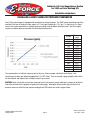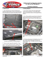
1
Edelbrock 4.6L Mustang GT Supercharger
Part #1580 & #1585
Edelbrock 4.6L Ford Supercharger System
for 2005 and later Mustang GTs
Installation Instructions
INTRODUCTION
Thank you for purchasing the Edelbrock 4.6L Ford Superchager System for the Mustang GT.
The Edelbrock E-Force Supercharger System for the 2005-2009 4.6L 3V Mustang utilizes
Eaton’s new Gen VI TVS Supercharger rotors, featuring a four lobe design with a full 160 deg.
of twist for maximum flow, minimum temperature rise, quiet operation, and the reliability for
which Eaton is known. These rotors however, are merely the foundation of the system. The
Edelbrock Supercharger is a complete system that maximizes efficiency and performance by
minimizing air restriction into, and out of, the supercharger. This results in maximum airflow,
with minimum temperature rise and minimum power consumption. In addition, Edelbrock
inverted the supercharger and packaged it down low in the valley, allowing for an incredible,
industry leading, 15 inches of runner length, maximizing low end torque. The supercharger
housing itself is integrated into the intake manifold for a seamless design with minimal
components, eliminating the possibility of vacuum leaks between gasket surfaces. The system
also utilizes a front drive, front inlet configuration giving it the shortest, least restrictive inlet
path on the market. Further minimizing inlet restriction is the massive 85mm electronic
throttle body that is included in the kit. Sitting right above the supercharger and below the
enormous runners is the largest air to water intercooler available, measuring an astonishing
110 square inches. Last but not least, the E-Force supercharger is without a doubt the best
looking engine compartment upgrade imaginable. It features a uniquely styled plenum, and
includes matching side covers. In summation, the Edelbrock supercharger will provide you
with the most power at the lowest amount of boost resulting in neck snapping performance
that is safe to operate on a completely stock engine. It is also pending 50 state emissions
legality, and can be had with an optional 3 yr 36,000 mile warranty so that there are no worries
when installing it on your brand new car.
Edelbrock Corporation, 2700 California Street, Torrance, CA 90503
Toll-Free Tech Line: 1-800-416-8628
Office: 310-781-2222
Tech E-Mail: [email protected]
©2009 Edelbrock Corporation
Catalog #1580
Page 2
Brochure #63-1580
Rev. 2/09 - AJ/mc
Edelbrock 4.6L Ford Supercharger System
for 2005 and later Mustang GTs
Installation Instructions
IMPORTANT WARNINGS
Proper installation is the responsibility of the installer. Improper installation will void warranty and may
result in poor performance and engine or vehicle damage.
Due to the complexity of the Edelbrock E-Force Supercharging system, it is recommend that this system only be
installed by a qualified professional with access to a service lift, pneumatic tools, and a strong familiarity with
automotive service procedures. To qualify for the optional 3-year, 36,000 mile warranty, it is necessary to have this
system installed by a certified ASE technician, Ford dealership, or Edelbrock approved installer. Failure to have this
system installed by a properly certified service center may result in voiding of both the optional warranty offered with
this sytem, as well as the standard Edelbrock parts warranty. Please contact the Edelbrock Technical Support
department if you have any questions regarding how this sytem and/or your installer of choice will affect any warranty
coverage for which your vehicle may qualify.
Any previously installed aftermarket tuning equipment must be removed and the vehicle returned to an as
stock condition before installing the supercharger.
Any equipment that directly modifies the fuel mixture or ignition timing of the engine can cause severe engine damage
if used in conjunction with the Edelbrock E-Force Supercharger System. This includes, but is not limited to: ignition
boxes, air/fuel controllers, OBDII programmers, and any other device that modifies signals to and/or from the ECU.
Aftermarket bolt-on equipment such as underdrive pulleys or air intake kits will also conflict with the operation of the
supercharger and must be removed prior to installation. Use of any of these products with the E-Force Supercharger
could result in severe engine damage.
91 octane or higher gasoline is required at all times. If your vehicle has been filled with anything less, it
must be run until dry and refilled with 91 or higher octane gasoline twice prior to installation.
This kit includes all the parts needed to install this system on ‘07 & ‘08 Mustang GTs only. ‘05 & ‘06
models will also need the 15804 Cooling Upgrade Kit, while ‘09 models will need the 15805 Hardware Kit.
Mustang GTs produced in 2005 and 2006 were equipped with a cooling system that mounted the thermostat on the
cold side of the radiator. The Edelbrock E-Force Supercharger was designed to take advantage of the improvements in
cooling efficiency that are offered by mounting the thermostat on the hot side as found in later models. Cooling
Upgrade Kit #15804 will allow owners of ‘05 & ‘06 model year Mustangs to retro-fit their cars with the later model
cooling systems, and is required before the supercharger can be installed. 2009 model year Mustangs recieved some
minor changes from previous model years and will require a different pulley nut and intake manifold gaskets, offered in
kit #15805, to operate correctly. It is strongly recommended that these parts be purchased, if needed, before beginning
installation of the supercharger.
©2009 Edelbrock Corporation
Catalog #1580
Page 3
Brochure #63-1580
Rev. 2/09 - AJ/mc
Edelbrock 4.6L Ford Supercharger System
for 2005 and later Mustang GTs
Installation Instructions
INSTALLING A BOOST GAUGE OR PRESSURE TRANSDUCER
Your E-Force supercharger is equipped with two options for measuring boost. The TMAP sensor mounted on top of the
manifold at the rear of the driver’s side, outputs a 0-5 volt signal through pins 1 & 2 (pin 1 is signal & pin 2 is signal
return,) that can be converted to an absolute pressure reading using the below calibration curve. Use of this signal
requires an ambient pressure correction for calculating boost pressure.
Voltage
0.62
0.80
1.09
1.40
1.71
2.17
2.46
2.70
2.94
3.25
3.55
3.84
4.15
4.46
4.76
Pressure
(psia)
2.70
3.69
5.70
7.69
9.70
12.70
14.70
16.21
17.70
19.71
21.70
23.71
25.70
27.70
29.70
The second option is to utilize the pressure port at the rear of the passenger side intake runner flange. Your
supercharger has been pre-drilled and tapped for a 1/8” NPT fitting. There is currently a plug sealing the hole, which
can be removed, and replaced with a fitting to adapt to your sensor.
CAUTION: Never cut into the vacuum lines leading to the fuel rail pressure sensor and bypass actuator, on the driver’s
side of the manifold, for the purpose of tapping in a boost gauge. Interruption of the vacuum signal to the fuel rail
pressure sensor can affect the fuel pressure reading to the PCM, which can result in engine failure!
©2009 Edelbrock Corporation
Catalog #1580
Page 4
Brochure #63-1580
Rev. 2/09 - AJ/mc
Edelbrock 4.6L Ford Supercharger System
for 2005 and later Mustang GTs
Installation Instructions
I. Hood Removal
II. Battery Removal
1. Use a panel puller to pry off two of the push-pins
holding the hood insulator in place on the passenger side,
then reach behind the insulator to disconnect the washer
hose from the T-junction at the passenger side nozzle.
3. Use an 8mm socket to loosen the negative battery
terminal clamp and remove it. Tuck it to the side to
prevent any accidental contact with the negative battery
terminal.
4. Use a 10mm socket to remove the nut on the positive
battery terminal that retains the alternator power wire.
Detach this wire from the terminal, then loosely reinstall
the nut.
Detach hose retaining clip, then remove these two pins.
5. Use an 8mm socket to loosen and remove the positive
battery terminal clamp, then tuck the wire over to the
side.
Pull hose off here.
(Insulator fully removed for illustrative purposes.)
6. Pull the insulating sleeve off of the battery, then use an
8mm socket to loosen the long bolt that secures the
battery tie-down strap. The battery can then be removed
and set aside.
2. Have an assistant support the hood while a 10mm
socket is used to remove the four bolts attaching it to its
hinges. Lift the hood off the vehicle and set it aside.
©2009 Edelbrock Corporation
Catalog #1580
Page 5
Brochure #63-1580
Rev. 2/09 - AJ/mc
Edelbrock 4.6L Ford Supercharger System
for 2005 and later Mustang GTs
Installation Instructions
7. Use a 10mm socket with a 12” extension bar to
remove the three bolts holding the battery tray in place,
then use a panel puller to detach the wiring harness clip.
Remove and set aside the tray.
Bolts
III. Removing Engine Components
9. Detach the charge motion control valve (CMCV)
electrical connector at the rear of the manifold. Seperate
the wiring retainers from the intake manifold stud and the
CMCV bracket, then move the wiring harness to the side.
Wiring Harness Clip
8. Use a flat blade screwdriver to pry up the head of the
six push-pins that retain the radiator shroud, then use a
panel puller to fully remove the push-pins. Lift the shroud
off the car and set it and the push-pins aside.
10. Detach the throttle position sensor (TPS) and
electronic throttle control (ETC) connectors from the
throttle body.
ETC
©2009 Edelbrock Corporation
Catalog #1580
Page 6
TPS
Brochure #63-1580
Rev. 2/09 - AJ/mc
Edelbrock 4.6L Ford Supercharger System
for 2005 and later Mustang GTs
Installation Instructions
11. Detach the mass airflow sensor electrical connector
from the air filter outlet tube.
14. Disconnect and remove the passenger side PCV hose.
This hose will not be reused.
15. Detach the electrical connectors from all eight fuel
injectors and the fuel pressure sensor.
12. Disconnect the evaporative emissions tube from the
intake manifold and move it to the side.
16. Disconnect the vacuum hose from the fuel pressure
sensor.
13. Disconnect the PCV line from where it is connected to
the driver side valve cover, then disconnect it from the
intake manifold and remove it. This hose will not be
reused.
17. Detach the battery cable anchors from the fuel rail
bolts by pulling upward firmly.
©2009 Edelbrock Corporation
Catalog #1580
Page 7
Brochure #63-1580
Rev. 2/09 - AJ/mc
Edelbrock 4.6L Ford Supercharger System
for 2005 and later Mustang GTs
Installation Instructions
18. Remove the fuel line lock clip and let it dangle.
22. Remove the retaining clips that hold in the injectors
and set them aside for reinstallation later, along with the
rails. The stock injectors will not be reused.
19. Use a 5/8” fuel line removal tool to disconnect the
fuel supply line from the fuel rails. Use a shop rag
wrapped over the connection to absorb the fuel remaining
in the system.
23. Use a flat head screwdriver to loosen the worm
clamps that retain the air inlet tube between the throttle
body and air filter cover, then remove the tube.
20. Disconnect the vacuum hose connected to the brake
booster.
Pull hose off nipple, do not remove fitting from booster.
21. Loosen the four studs that hold down the fuel rails.
The rails and injectors can then be removed together and
set aside.
©2009 Edelbrock Corporation
Catalog #1580
24. The manifold bolts may now be removed with a
10mm socket and the intake lifted off the engine. There
is no need to detach the throttle body as it will not be
reused. Use an extension bar to reach the two center
bolts hidden between the runners.
Page 8
Brochure #63-1580
Rev. 2/09 - AJ/mc
Edelbrock 4.6L Ford Supercharger System
for 2005 and later Mustang GTs
Installation Instructions
25. 2005-2008 applications should remove the o-ring
seals from the intake manifold and inspect them for
damage. Any damaged seals must be replaced; the rest
will be retained for reuse with the supercharger runners.
2009 and later applications will use the o-rings supplied
in the 15805 Hardware Kit.
27. Unlatch the air cleaner cover, then use a Torx-20
driver to remove the MAF sensor from the outlet tube.
Apply a small strip of tape to the MAF sensor to
distinguish it from the modified unit supplied with this kit.
28. Use a 10mm socket to unbolt the air cleaner housing
and remove it.
26. Use a soft cloth to clean any irregularities on the
sealing surfaces of the cylinder heads. Use two strips of
masking tape to prevent any debris from entering the
exposed ports.
29. Loosen the tensioner arm by using a 1/2” drive
breaker bar, and remove the serpentine belt. This belt can
be discarded as it will not be reused.
30. Use a 13mm socket to remove the two nuts at the
bottom of the alternator.
©2009 Edelbrock Corporation
Catalog #1580
Page 9
Brochure #63-1580
Rev. 2/09 - AJ/mc
Edelbrock 4.6L Ford Supercharger System
for 2005 and later Mustang GTs
Installation Instructions
31. Use a 10mm socket to remove the two outer
alternator bracket bolts, and an 8mm socket to remove
the two inner alternator bracket bolts.
IV. Front Fascia
34. Use a 10mm socket to remove the two upper front
bumper cover bolts, located between the grille and
headlights.
8mm
10mm
32. Use a panel puller to remove the harness locating pin
from the alternator bracket, remove the bracket, then
disconnect the alternator electrical connector. Trace the
alternator harness back to where it clips into the main
harness and detach it. This wire may now be discarded.
33. Push aside the protective boot to access and remove
the nut retaining the alternator power wire. The power
wire will not be reused and can be discarded. The
alternator can now be lifted out and set aside.
©2009 Edelbrock Corporation
Catalog #1580
35. Use a jack and jack stands or a service lift to raise
the front of the vehicle. Use a 5.5mm (or 7/32”) socket to
remove the seven bolts that retain the lower splash shield,
then set the shield and bolts aside.
36. Remove the five push-pins and three screws that
secure each of the front inner fender wells. Note that the
front inner fender wells are divided in two sections, but
you will only need to remove the forward half. Turn the
head of push-pins that have a philips head recess on
them about a quarter turn or until the head pops up, then
fully remove the pin with a panel puller. Remove and set
aside the forward half of both front inner fender wells.
Page 10
Brochure #63-1580
Rev. 2/09 - AJ/mc
Edelbrock 4.6L Ford Supercharger System
for 2005 and later Mustang GTs
Installation Instructions
37. Reach through the fender well with a 10mm socket to
loosen the two nuts on each side that attach the front
bumper cover to the body.
V. Cooling System
40. To avoid injury be sure the engine has fully cooled
before draining the cooling system. Release any excess
pressure in the system by using a cloth to rotate the
radiator cap counterclockwise. Step away from the
vehicle if any hot vapor is vented, then remove the cap.
38. Pull the front bumper cover down off the studs, then
forward slightly to access the fog lamp, turn signal and
running light electrical connectors. Once these have been
detached, the entire front cover can be removed with the
lights and indicators in place.
41. Place a drain pan below the radiator petcock on the
passenger side, then use a 19mm wrench to open the
petcock and drain the coolant.
39. Use a panel puller to remove the four pins retaining
the foam insulator, then set them and the insulator aside.
NOTE: If this system is being installed on an ‘05 or ‘06
Mustang GT, you will need to have purchased the
Cooling Sysem Upgrade Kit #15804 before proceeding
with the installation. Otherwise, 2007 and later vehicles
should skip ahead to step 48.
©2009 Edelbrock Corporation
Catalog #1580
Page 11
Brochure #63-1580
Rev. 2/09 - AJ/mc
Edelbrock 4.6L Ford Supercharger System
for 2005 and later Mustang GTs
Installation Instructions
42. Use large pliers or a clamp removal tool to detach
both upper radiator hoses from the water crossover.
45. Disassemble the thermostat housing and remove the
thermostat. The thermostat itself can be discarded but
the o-ring will be reused.
43. Place shop rags in the engine valley to catch excess
coolant, then disconnect the heater hose connected to the
bottom of the crossover. Use a 10mm socket to unbolt
and remove the water crossover. Remove and save the orings for reuse later.
46. Use a 15mm socket to remove the hose bracket.
44. Disconnect the lower hoses joining the thermostat
housing to the radiator, engine block and the bottom of
the coolant recovery tank. Seperate the hose clamps from
the end of the hoses and save them for reuse later.
47. Connect the radiator hose assembly supplied in the
15804 kit to the driver side radiator fitting and the engine
block fitting behind the power steering pump using the
stock hose clamps. The long segment should be
connected to the bottom of the coolant recovery tank, also
reusing the stock hose clamp.
Radiator
Engine Block
Coolant Recovery Tank
NOTE: ‘05-’06 applications can skip ahead to step 51,
the following steps only apply to ‘07 and later Mustangs.
©2009 Edelbrock Corporation
Catalog #1580
Page 12
Brochure #63-1580
Rev. 2/09 - AJ/mc
Edelbrock 4.6L Ford Supercharger System
for 2005 and later Mustang GTs
Installation Instructions
48. Disconnect the upper radiator hose from the
thermostat housing and radiator, then set it aside.
49. Remove and save the thermostat, its housing and the
o-ring for later reuse.
55. Hang the water pump on the passenger side outer
bumper bolts while pushing the outlet hose onto the inlet
nipple of the heat exchanger. Secure the hose with a
clamp, and the water pump bracket with two of the M8
flange nuts supplied.
50. Unbolt and remove the water crossover from the front
of the engine block and unclip the heater hose from the
bottom. Save the o-ring seals for later reuse.
VI. Installing Intercooler Accessories
51. Replace the two upper inside bumper bolts with the
two M8 x 30mm long hex flange bolts included in
hardware bag #5.
56. Install the long 3/4” hose onto the driver side barb of
the heat exchanger and secure it with a clamp.
52. Replace both outer bumper bolts on the passenger
side with the two M8 x 30mm hex flange bolts supplied in
hardware bag #5.
53. Hang the heat exchanger behind the bumper
reinforcement on the inner bumper bolts replaced in step
52 and secure it with the four M8 flange nuts supplied in
hardware bag #5.
54. Install the supplied 5” piece of 3/4” hose onto the
outlet of the intercooler water pump, secure it with the
supplied hose clamp, then slide a second clamp onto the
hose to secure it on the heat exchanger.
VII. Wiring
57. Locate the large multi-pin connector (C110) secured
to the driver side of the PCM bracket. This connector has
12 pins in ‘05 Mustangs, while ‘06 and later cars have a
16-pin connector in this location.
58. Seperate the harness connectors. ‘05 and ‘06
applications should trim enough electrical tape from the
harness behind the chassis side connector (closest to the
radiator) to pull out 2” of wire from the convoluted tubing.
‘07 and later applications will trim the electrical tape from
behind the engine connector (closest to the firewall) to
pull out 2” of wire from the convoluted tubing.
Chassis Side for
‘05 & ‘06 Mustangs
©2009 Edelbrock Corporation
Catalog #1580
Page 13
Engine Side for
‘07 & Later Mustangs
Brochure #63-1580
Rev. 2/09 - AJ/mc
Edelbrock 4.6L Ford Supercharger System
for 2005 and later Mustang GTs
Installation Instructions
59. ‘05 applications should locate the red wire in pin 10,
near the bottom of the connector. ‘06 applications should
locate the red wire in pin 2, at the top left of the
connector. ‘07 and later applications should locate the
red wire with the yellow stripe in pin 16.
62. Remove the relay from the relay socket on the
supplied intercooler water pump wiring harness.
63. Mount the pump relay on the lower passenger side
fascia bracket bolt. Apply a light coat of blue loctite to the
bolt threads, then secure the relay holder with an M6 nut
supplied in hardware bag #7. Reinstall the relay.
‘06 Model Year Example
60. Once you have located the appropriate wire for your
model year application, cut the wire 1.5” back from the
connector and strip the end on the harness side.
64. Route the ground wire to the upper fascia bracket
bolt and secure it with an M6 nut from hardware bag #7.
61. Insert the the exposed end of the stripped harness
wire into the butt connector pre-installed on the yellow
wire with the red stripe of the intercooler water pump
harness. Secure the connection by crimping the butt
connector with an appropriate crimp tool, then use a heat
gun on the connection until it shrinks.
©2009 Edelbrock Corporation
Catalog #1580
65. Route wires under the fuse box and attach the fuse
holder to the passenger side strut tower with a 10mm
socket and the M6 bolt supplied in hardware bag #7. This
bolt hole is threaded on ‘07 and later Mustangs, but ‘05
and ‘06 will need to use an M6 nyloc nut supplied in the
#15804 Cooling Upgrade Kit.
Page 14
Brochure #63-1580
Rev. 2/09 - AJ/mc
Edelbrock 4.6L Ford Supercharger System
for 2005 and later Mustang GTs
Installation Instructions
66. Use a 10mm socket to attach the power wire to the
power terminal on the fuse box
70. Detach ETC connector from supplied ETC extension
harness and raise wedge lock. Insert the red wire with
the yellow stripe into Pin 1 of the new ETC connector by
aligning the slot on the wire terminal with the tab in the
connector and pushing gently until it clicks into place,
then insert the blue wire with the yellow stripe into Pin 2
and seat it gently.
67. Route the water pump electrical connector below the
fuse box and around the washer fluid reservoir and plug it
into the intercooler water pump.
68. Locate the ETC electrical connector on the main
engine wiring harness, previously removed from the driver
side of the throttle body. Use a hooked terminal removal
tool or dental pick to elevate the red plastic wedge lock
inside the connector.
69. Use a de-pinning tool, needle or safety pin to slide
under the terminal and lift the locking tab while pulling
gently on the corresponding wire to de-pin the connector.
De-pin both wires and remove the connector.
Pin 2
Pin 1
ETC Connector
71. Once both wires are seated in the connector, depress
the red wedge lock to secure them in place.
72. Install the short ETC harness extension onto the
newly pinned connector.
73. Locate the TPS connector on the passenger side of
the main engine wiring harness. Use a small pick or
screwdriver to release the center locking tab while prying
up on the white wedge lock.
Recommended Tools
©2009 Edelbrock Corporation
Catalog #1580
Page 15
Brochure #63-1580
Rev. 2/09 - AJ/mc
Edelbrock 4.6L Ford Supercharger System
for 2005 and later Mustang GTs
Installation Instructions
74. Once the wedge lock is elevated, de-pin all four wires
on the connector using the same procedure as with the
ETC connector.
75. Detach the TPS connector from the TPS/Alternator
extension harness and raise the wedge lock by pushing
the center lock tab and pulling up. Align the slot on the
wire terminal with the tab in the connector, then insert the
yellow wire with the white stripe into Pin 1 of the TPS
Connector and seat it gently.
Pin #1
80. Locate the electrical connector on the main harness
previously occupied by the alternator control wiring
harness. Attach the round alternator connector on the
supplied TPS/Alternator harness into this connector and
route the harness around the back of the engine bay, then
forward along the driver side cylinder head.
81. Locate the MAF sensor connector on the driver side
of the main engine wiring harness. Use a pick shaped
tool to hook the center tab provision on the face of the
connector and pry the wedge lock out altogether.
Pin #2
Pin #3
82. Use a razor or sharp knife to cut the electrical tape
directly behind the connector, then pull the connector
away from the convoluted tubing until 2” of wire have
been exposed.
Pin #4
83. Use a small needle or safety pin to de-pin and
remove the two wires on the right side (gray and gray
with a red stripe).
TPS Connector
76. Insert the red wire with the green stripe into Pin 2 of
the TPS Connector and seat it gently.
77. Insert the black wire with the green stripe into Pin 3
of the TPS Connector and seat it gently.
78. Insert the grey wire with the white stripe into Pin 4 of
the TPS Connector and seat it gently. Depress the white
wedge lock to secure the wires in place.
79. Attach the electrical connector of the TPS/Alternator
wiring harness to the connector you just installed.
©2009 Edelbrock Corporation
Catalog #1580
Page 16
Brochure #63-1580
Rev. 2/09 - AJ/mc
Edelbrock 4.6L Ford Supercharger System
for 2005 and later Mustang GTs
Installation Instructions
84. Detach the TMAP connector from the supplied TMAP
wiring harness and raise the wedge lock. Insert the gray
wire into Pin 1 of the supplied TMAP connector and seat it
gently.
Pin 2
VIII. Cooling System Modifications
89. Route the molded hose under the fuse box and onto
the inlet at the top of the water pump. Secure it with a
clamp.
Pin 1
TMAP Connector
85. Insert the gray wire with the red stripe into Pin 2 of
the TMAP connector and seat it gently. Depress the red
wedge lock to secure the wires in place.
90. Remove the two inner passenger side strut tower
nuts and hang the recovery tank bracket from the
exposed bolts. Do not reinstall strut nuts at this time.
86. Reinstall the red wedge lock into the OEM MAF
sensor connector and push it gently until seated.
91. Slide the molded hose onto the bottom barb of the
tank and secure it with a clamp.
87. Tuck the wires back into the convoluted tubing and
secure them with a small strip of electrical tape.
88. Install the TMAP wiring harness extension onto the
new connector and route it towards the back of the
engine bay.
©2009 Edelbrock Corporation
Catalog #1580
Page 17
Brochure #63-1580
Rev. 2/09 - AJ/mc
Edelbrock 4.6L Ford Supercharger System
for 2005 and later Mustang GTs
Installation Instructions
92. Reinstall the foam bumper insulator and secure it in
place with the stock body pins.
93. Reconnect the fog lights and indicators, then replace
the fascia onto the front of the car. Reach through the
fender wells to reattach the nuts that secure it.
99. Once the coolant pipes have been separated, reinstall
the smaller diameter of the two by gently sliding it onto
the nipple in the engine valley and securing it onto the
back of the head with the stock bolt. The lower hose and
larger diameter hard line can be discarded.
94. Reinstall the screws and push in rivets that secure
the inner fender wells, then reinstall the upper front fascia
bolts.
95. Replace the lower splash shield and the radiator
shroud and secure them with the stock fasteners. The
vehicle can now be lowered.
96. Two hard coolant lines are held in place in the engine
valley by a bracket bolted to the rear of the passenger
side cylinder head. Remove the bolt holding this bracket
in place, then unclip the lower hose from the firewall.
100. Reattach the upper heater hose to the hard line with
the stock hose clamp.
IX. Installing New Components.
97. Unclamp the upper hose from the hard line, then
remove both hard lines, being careful not to damage the
nipple in the bottom of engine valley.
101. Use a 13mm socket to remove the two idler pulleys
on the driver’s side of the engine, but save one of the
mounting bolts for later.
98. Place the coolant pipes in cloth wrapped vice jaws to
avoid damaging them, then use a hacksaw or cut-off
wheel to seperate the tubes by cutting the two brackets,
as shown below.
©2009 Edelbrock Corporation
Catalog #1580
Page 18
Brochure #63-1580
Rev. 2/09 - AJ/mc
Edelbrock 4.6L Ford Supercharger System
for 2005 and later Mustang GTs
Installation Instructions
102. Install the smaller of the two Edelbrock supplied
idler pulleys onto the alternator bracket with the open end
facing the bracket. Secure it with a small amount of blue
Loctite applied to the bolt saved in the previous step, then
use a 13mm socket to torque it down to 18 ft/lbs.
104. Use a 13mm socket to remove the two upper driver
side front cover bolts, and an 18mm socket to remove
the bottom driver side bolt, as shown below.
105. Slide the larger of the two Edelbrock supplied idler
pulleys onto the lower idler boss of the front cover with
the open side facing the engine block.
103. Remove the alternator mounting stud on the driver’s
side of the engine using a 5.5mm socket, or thread a
second nut onto the stud as shown, and use a 13mm
wrench on the nut closest to the block to remove the stud.
106. Use a 12mm deep socket and a small amount of
blue loctite to install the alternator bracket using the bolts
supplied in hardware bag #3. The upper two provisions
will use the 65mm bolts, while the bottom provision will
use the 75mm bolt. The center hole will use a 35mm bolt
that will pass through both the bracket and pulley, and
then thread into the front cover.
65mm
©2009 Edelbrock Corporation
Catalog #1580
Page 19
35mm
75mm
Brochure #63-1580
Rev. 2/09 - AJ/mc
Edelbrock 4.6L Ford Supercharger System
for 2005 and later Mustang GTs
Installation Instructions
X. Installing Spark Plugs (Not Included In 1585)
XI. Installing the Supercharger
NOTE: The following steps only apply to Mustangs built
prior to December, ‘07. Later applications have the
proper heat range spark plug installed from the factory
and will not use the supplied plugs. These Mustangs
should skip ahead to ‘Installing the Supercharger’.
Early model spark plugs that need to be replaced have a
ground strap that extends all the way around the
electrode, while late models have a standard ‘L’ shape.
‘08 Mustangs should remove a single plug to determine
their style of plug, and if replacement is necessary.
Early Model Plug
112. Install the Edelbrock supplied heater hose on the
firewall connector, and lay it to the side for now.
113. Remove the supercharger assembly from its packing
container and install the o-ring seals, removed from the
stock manifold on early applications and supplied in the
#15805 Hardware Kit for 2009 applications, into the
grooves on the bottom of the runners. Be sure to line up
the tab on the o-rings with the notches provided.
107. Use a 7mm socket to remove the bolt that secures
each ignition coil, then use a slight twisting motion to
remove the coils.
108. Use compressed air to clean out the spark plug well,
then remove the stock spark plugs with a 9/16” spark
plug socket.
114. Be sure that the engine bay and environs are clean
and free of debris, then remove the masking tape used to
protect the intake ports from contamination.
109. Coat the threads of the Edelbrock supplied spark
plugs with anti-sieze, and torque them to 25 ft/lbs.
115. Install the o-ring gaskets removed from the stock
water crossover into the supplied crossover.
110. Apply a thin layer of dielectric grease to the inside of
the coil boots, then reinstall them onto the plugs.
111. Tighten the coil retaining bolts to 44 in/lbs.
©2009 Edelbrock Corporation
Catalog #1580
Page 20
Brochure #63-1580
Rev. 2/09 - AJ/mc
Edelbrock 4.6L Ford Supercharger System
for 2005 and later Mustang GTs
Installation Instructions
116. Insert the water crossover into the gap between the
intercooler manifold and the and the supercharger drive
pulley. There are no bolts that directly attach the
crossover to the manifold, so it will need to be held steady
as the supercharger is installed.
120. Use a 10 mm socket to install the supplied intake
bolts, and torque them to 8 ft/lbs in the sequence shown.
121. Install the new fuel injectors (not included in 1585)
into the stock fuel rails by applying a bit of o-ring lube to
both o-rings of each injector, sliding the stock retaining
clips onto the injectors, then pushing each injector into the
rail until the clips snap into place.
117. With the help of an assistant or a cherry picker,
carefully lower the supercharger assembly onto the
cylinder heads. Be especially careful not to pinch any
wires between the supercharger and the cylinder heads.
Orient the attached 3/8” hose around the back of the
manifold in the direction of the brake booster as the
supercharger is lowered.
118. Push the supercharger as far to the rear of the
engine bay as space allows so that the supplied bolts can
be inserted into the provisions on the crossover. Pull the
crossover forward against the bolts, then torque them to
7-1/2 ft/lbs with a 10mm socket.
122. Align each of the fuel injectors with its prospective
well, then pull the top of the rail outboard so that the the
brackets will clear the runner flanges as you push the rail
down. Make sure that the TMAP wiring harness is routed
below the driver side rail. The rails and injectors are fully
seated once the rail brackets contact the runner bosses.
Use a 5mm allen tool to secure the rails with the M6
socket head bolts supplied in hardware bag #2.
119. Ensure correct alignment of the supercharger by
looking through the injector holes to verify that they are
aligned with the injector provisions of the cylinder head
and that the manifold is centered left to right as well as
front to back on the engine block.
©2009 Edelbrock Corporation
Catalog #1580
Page 21
Brochure #63-1580
Rev. 2/09 - AJ/mc
Edelbrock 4.6L Ford Supercharger System
for 2005 and later Mustang GTs
Installation Instructions
123. Install the 3/8” vacuum hose attached to the rear of
the manifold onto the brake booster nipple and secure it
with the spring clamp provided.
126. Connect the EVAP hose to the hard line at the front
of the manifold.
127. Reconnect the fuel pressure sensor to the main
wiring harness. Be sure to use the connector that does
not have a red locking tab, the connector with a red
locking tab is for the TPS.
124. Install the 1/4” vacuum hose attached to the rear of
the manifold onto the fuel pressure sensor.
128. Plug wiring harness extension into TMAP sensor.
125. Connect each of the fuel injectors to the appropriate
terminal on the main wiring harness, then reconnect the
fuel line to the fuel rail and secure it with the lock clip.
XII. Modifying Stock Components
129. Use a 10mm socket to loosen the three bolts that
hold the tensioner in place and remove the arm.
©2009 Edelbrock Corporation
Catalog #1580
Page 22
Brochure #63-1580
Rev. 2/09 - AJ/mc
Edelbrock 4.6L Ford Supercharger System
for 2005 and later Mustang GTs
Installation Instructions
130. Place the tensioner in a cloth wrapped vice and use
a grinding wheel or hacksaw to remove the stop.
134. Use a flat head screwdriver to pop off the bearing
cover on the alternator pulley. ‘05-’08 applications should
use the supplied tool with an impact wrench to remove
the stock pulley. ‘09 and later applications should use a
24mm allen tool with an impact wrench.
131. Use a grinding wheel or file to ensure that the area
that was ground down is smooth and free of burrs.
135. Install the new alternator pulley with the nut
supplied in hardware bag #3 (with kit #15805 for ‘09
Mustangs) and blue Loctite.
132. Use a 10mm socket to install the three tensioner
brace bolts, making sure to line up the square holes.
133. Use a 10mm socket to reinstall the tensioner.
©2009 Edelbrock Corporation
Catalog #1580
136. Attach the stock protective boot to the new
alternator power wire and fasten it to the alternator
terminal with a 10mm socket. Route the wire around the
back of the engine towards the battery, then attach the
new alternator control wiring harness connector from the
TPS/Alternator extension harness to the alternator.
Page 23
Brochure #63-1580
Rev. 2/09 - AJ/mc
Edelbrock 4.6L Ford Supercharger System
for 2005 and later Mustang GTs
Installation Instructions
137. Unbolt the power steering reservoir so that it can be
pushed out of the way while installing the alternator.
140. Route the supplied serpentine belt according to the
diagram provided below by using a 1/2” breaker bar to
twist the belt tensioner enough to allow the belt to slide
into place.
138. Thread the serpentine belt through the alternator
bracket and over the alternator pulley before securing the
alternator to the bracket with the two M8 x 40mm bolts
supplied in hardware bag #3. Verify that the alternator is
fully seated on the bolts before torquing them to 18 ft/lb.
XIII. Installing the Throttle Body
141. Use 8mm and 10mm sockets to unbolt the OEM
throttle body from the stock intake manifold, using care
not to damage the motor housing.
139. Use a 12mm socket to fasten the alternator strap to
the front cover using the M8 x 60mm long bolt supplied in
hardware bag #3, then tighten it to 18 ft/lbs. Secure the
strap to the alternator with the M6 x 20mm bolt from
hardware bag #3 and tighten it to 8 ft/lbs.
142. Use a T20 Torx driver to remove the motor housing,
plastic capped spring, and TPS from the OEM throttle
body. WARNING: Rotating the TPS when removing or
installing it may damage the internals beyond repair.
Plastic Capped Spring
©2009 Edelbrock Corporation
Catalog #1580
Page 24
ETC
TPS
Brochure #63-1580
Rev. 2/09 - AJ/mc
Edelbrock 4.6L Ford Supercharger System
for 2005 and later Mustang GTs
Installation Instructions
143. Carefully remove the motor housing cap.
147. Reinstall the motor housing cap by lining up the tabs
and applying light pressure.
148. Reuse the stock bolts to install the TPS on the new
throttle body by lining up the locating tab and pushing it
straight on. Be careful to avoid rotating the TPS during
installation.
149. Verify correct installation by pushing the butterfly
open and closed a few times, making sure that it doesn’t
stick or bind in a particular position.
144. Install the plastic capped spring into the new
Edelbrock supplied throttle body so that the pigtail end is
hooked into the catch slot of the gear on the end of the
throttle shaft.
150. Align the throttle body gasket on the flange, then
install the throttle body onto the inlet elbow with the bolts
supplied in hardware bag #4. Open the throttle blade and
align the two parts so that there is a smooth transition
before tightening the bolts.
145. Install the ETC motor over the plastic capped spring
and tighten the screws that hold it in place.
146. Use needle nose pliers to rotate the plastic spring
cap roughly half a turn counter-clockwise until the two
tabs line up with the notches in the motor housing. Pull
up on the cap until it snaps into place.
©2009 Edelbrock Corporation
Catalog #1580
151. Use a cut off wheel or hacksaw and drill to cut the
base of the airbox off as shown, then reinstall the airbox.
Page 25
Brochure #63-1580
Rev. 2/09 - AJ/mc
Edelbrock 4.6L Ford Supercharger System
for 2005 and later Mustang GTs
Installation Instructions
152. Install the new high flow air filter in the airbox.
156. Install the ETC extension harness and attach the
electrical connectors for the TPS and ETC stepper motor.
153. Use a T20 Torx driver to install the new MAF sensor
in the air cover outlet tube, torque the two screws that
retain it to 18 in/lbs., then reinstall the cover.
154. Install the throttle body elbow onto the throttle body
and secure it with the provided hose clamps. The flexible
elbow should be oriented so that it can be easily mated to
the air cleaner cover outlet tube.
157. Install the 12” piece of 3/4” hose from the recovery
tank to the intercooler manifold fitting. Secure each end
with a clamp.
158. Route the other end of the hose up to the intercooler
manifold outboard of the A/C line, avoiding close proximity
to the exhaust manifold and power steering pump, and
attach it to the manifold fitting with a clamp.
155. Route the new driver side PCV hose between the
valve cover and intake elbow, then install the passenger
side PCV hose between the fitting on the throttle body and
valve cover.
159. Install the thermostat, o-ring & housing (thermostat
and housing supplied in #15804 for ‘05-’06 applications,
all model years reuse stock o-ring) onto the driver side of
the water crossover. Torque the thermostat housing bolts
to 7-1/2” ft/lbs. Install the stock molded hose onto the
thermostat housing and line the other end up with the
passenger side radiator fitting. Trim 1-1/2” from the
radiator side of the hose to achieve the best fit.
©2009 Edelbrock Corporation
Catalog #1580
Page 26
Brochure #63-1580
Rev. 2/09 - AJ/mc
Edelbrock 4.6L Ford Supercharger System
for 2005 and later Mustang GTs
Installation Instructions
160. Install the supplied heater hose onto the heater tube
on the passenger side of the water crossover.
161. Verify that the coolant petcock is closed, then refill
the coolant system.
162. Fill the intercooler system with a 50/50 blend of
water and coolant poured into the recovery tank. Fill the
tank until the water level is roughly 1” from the top of the
threaded neck.
165. Install the coil cover brackets onto the coil covers
with the raised portion of the bracket facing towards the
top of the cover, while the lower ‘L’ portion faces in
towards the center of the cover, as shown below.
166. Apply a small amount of blue loctite to the thread of
each bolt supplied in hardware bag #8, then tighten them
with an 1/8” allen wrench while holding the nut steady
with a 5/16” wrench.
XIV. Installing Coil Covers (Does Not Apply To 1585)
163. Lift the recovery tank off the strut tower bolts and
fold it forward.
167. Remove the engine oil dipstick.
168. Lube the grommet supplied with the driver side
cover with silicone spray, then slide it over the dipstick
tube and wiggle it into place with your thumbs as you
lower the driver side cover into place.
164. ‘05 & ‘06 applications should tape off the strut
tower brackets to prevent damaging the covers during
installation. On some ‘05 & ‘06 vehicles, it may be
necessary to clearance the flange on the bottom of the
strut tower brackets in order for the covers to fit properly.
©2009 Edelbrock Corporation
Catalog #1580
Page 27
Brochure #63-1580
Rev. 2/09 - AJ/mc
Edelbrock 4.6L Ford Supercharger System
for 2005 and later Mustang GTs
Installation Instructions
169. Lower the driver side coil cover into place, orienting
the bracket so that it lines up with the bolt provision
below the TMAP sensor. Use caution not to pinch the
TMAP wire harness as you are fastening the cover bracket
to the runner with the supplied thumb screws. Verify that
the cover stands are flush on the valve cover and not
pinching any wires or hoses. Install the oil dipstick.
174. Verify that water is flowing briskly through the
recovery tank, then install the cap.
175. Have an assistant support the hood while you
tighten the four bolts that secure it to its hinges. Be
careful to verify that it is properly aligned and that the
supercharger has nothing on top of it before you attempt
to close the hood.
176. Reattach the washer nozzle hose and replace any
hood insulator body pins that were removed.
XV. Flashing the ECU
177. Plug the supplied programming module into the
OBD-II port of the car, located below the steering column.
170. Install the passenger side cover by lowering it into
place and fastening the thumbscrews. Use caution not to
pinch any wire harnesses or heater hoses.
171. Replace the recovery tank on the strut tower bolts,
then install and torque the strut tower nuts to 26 ft/lbs.
178. Once the main menu has loaded, press the central
‘select’ button on the controller to access the
‘Performance Tune’ option.
172. Reinstall the battery tray, battery, protective sleeve
and tie down strap, then secure the battery. Reconnect
the positive and negative clamps to their respective
terminals, and connect new alternator power wire to the
positive battery terminal.
173. Turn the ignition key to the ‘ON’ position.
©2009 Edelbrock Corporation
Catalog #1580
Page 28
Brochure #63-1580
Rev. 2/09 - AJ/mc
Edelbrock 4.6L Ford Supercharger System
for 2005 and later Mustang GTs
Installation Instructions
179. Read the discalimer carefully, then choose ‘Agree’
and press select.
192. Press select to confirm your choice.
193. An asterisk will appear next to the ‘Axle Ratio’ option
to signify that your changes have been saved. If your
Mustang is equipped with non-stock tires, choose the ‘Tire
Revs per Mile’ option and press select; otherwise,
continue to step 193.
180. Use the arrow buttons to select your transmission,
then press select to confirm your selection.
181. Select ‘Edelbrock E-Force 5psi’ from the menu.
182. Read description and press select.
183. The programmer will automatically save a copy of
your existing engine tune. Press select to continue.
184. Turn the ignition key to the ‘OFF’ position when
prompted, but do not remove it.
194. You will need to check your tire manufacturer’s
website to determine the tire revs per mile for your tires.
The stock tires get 771 revs per mile.
185. Turn the ignition key to the ‘ON’ position when
prompted, but do not attempt to start the car. the
programmer will automatically start saving the stock
calibration.
195. Use the directional buttons to select the number
closest to the tire revs per mile figure provided by your
tire manufacturer. Press select again to confirm your
selection.
186. Once complete, follow the on-screen prompts
regarding key position until you are given the option to
‘Install Tune’ or ‘Modify Tune’. Choose ‘Modify Tune and
press select.
196. Press escape twice to return to the Performance
Tune menu. Choose ‘Install Tune’ and press select.
197. Confirm your choice by pressing select.
198. Follow the on-screen prompts regarding key position
until you recieve notification the tune installation is
complete.
187. Read the disclaimer and press select.
199. When the download is complete you will be
prompted to disconnect the DiabloSport Performance
Tuner from the OBD-II port of your vehicle.
188. Select ‘Modify Parameters’ and press select.
189. Press select to choose ‘Axle Ratio’.
190. Press select to choose ‘Axle Ratio’, again.
200. If you have access to a diagnostic scan tool, run a
‘Key On, Engine Off’ test to verify that all connectors are
properly installed, otherwise move on to the next step.
191. Use the directional buttons to choose the number
closest to your axle ratio (printed on the differential cover)
and press select.
201. Start the car and verify a smooth idle. If you are
using a diagnostic scan tool, run a ‘Key On, Engine Run’
test.
©2009 Edelbrock Corporation
Catalog #1580
Page 29
Brochure #63-1580
Rev. 2/09 - AJ/mc