1
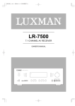
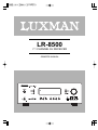
LR-8500
7.1 CHANNEL AV RECEIVER
OWNER'S MANUAL
Important Safety Instructions
IMPORTANT(for U.K.Customers)
CAUTION
The product shall not be exposed to dripping or
splashing and that no object filled with liquids, such
as vases, shall be placed on the product.
DO NOT cut off the mains plug from this equipment. If
the plug fitted is not suitable for the power points in
your home or the cable is too short to reach a power
point, then obtain an appropriate safety approved
extension lead or consult your dealer.
Do not install this equipment in a confined space
such as a book case or similar unit.
If nonetheless the mains plug is cut off, remove the
fuse and dispose of the plug immediately, to avoid a
possible shock hazard by inadvertent connection to
the mains supply.
This symbol means that the product is double
insulated and you do not need an earth connection
If this product is not provided with a mains plug, or one
has to be fitted, then follow the instructions given
below:
This symbol means that this product keeps to
the European safety and electrical interference directives
IMPORTANT. DO NOT make any connection to the
larger terminal which is marked with the letter E or by
the safety earth symbol | or coloured GREEN or
GREEN-and-YELLOW.
Y
The wires in the mains lead on this product are
coloured in accordance with the following code:
BLUE : NEUTRAL
BROWN : LIVE
As these colours may not correspond with the
coloured markings identifying the terminals in your
plug proceed as follows:
The wire which is coloured BLUE must be connected
to the terminal which is marked with the letter N or
coloured BLACK.
The wire which is coloured BROWN must be connected to the terminal which is marked with the letter L or
coloured RED.
When replacing the fuse only a correctly rated
approved type should be used and be sure to re-fit the
fuse cover.
IF IN DOUBT — CONSULT A COMPETENT ELECTRICIAN.
-2-
Table of Contents
Thanks for choosing LUXMAN.
Read this manual carefully to get the best performance from this unit.
Before Use ......................................................................4
Video Operations .........................................................25
Description......................................................................5
System Configuration..................................................25
Connections....................................................................6
- Function Setup...........................................................26
- Speakers, PRE OUT, AC OUTLET, RS-232C .............8
- Surround Setup..........................................................26
- Audio Components......................................................9
- Dolby Surround..........................................................27
- Video Components ....................................................10
- Speaker Setup ...........................................................28
- Advanced Connecting ..............................................11
- Distance Adjust .........................................................29
- Antennas.....................................................................12
- CH Level Adjust..........................................................29
Control Functions.........................................................13
- Preference Setup ......................................................29
Basic Operations .........................................................17
- Zone II Setup..............................................................30
Surround Mode ............................................................19
- Room Auto Setup.......................................................30
Night Mode ...................................................................19
Zone II Operation .........................................................20
Controlling other Components Connected
to the LR-8500 ......................................................................33
Speaker Configuration ................................................21
Programming the Remote...........................................34
Tuner Operation ...........................................................23
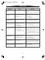
Troubleshooting ...........................................................39
RDS.................................................................................24
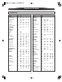
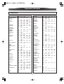
Specifications...............................................................40
PTY .................................................................................24
-3-
Before Use
Read this before operation
Back-up Memory Function
< As the unit may become warm during operation,
always leave sufficient space above the unit for ventilation.
This is the function which preserves the preset memory and most-recent memory functions. In the event
of a power failure, or if the power cord of this unit is
disconnected from the electric outlet, the back-up
memory will preserve the preset memory and mostrecent memory functions for as long as approximately 15 days.
< The voltage supplied to the unit should match the
voltage as printed on the rear panel. If you are in any
doubt regarding this matter, consult an electrician.
If the power supply is interrupted for 15 days or
longer, the memory settings will be erased.
< Choose the installation location of your unit carefully.
Avoid placing it in direct sunlight or close to a source
of heat. Also avoid locations subject to vibrations
and excessive dust, heat, cold or moisture.
When to Use RESET
< When this system is subjected to an electrical
shock.
< Do not open the cabinet as this might result in damage to the circuitry or electrical shock. If a foreign
object should get into the set, contact your dealer.
< When the power is irregular.
In these cases, try the following
< When removing the power plug from the wall outlet,
always pull directly on the plug, never yank the cord.
Press the ENTER button for more than 5 seconds.
< Do not attempt to clean the unit with chemical solvents as this might damage the finish. Use a clean,
dry cloth.
Note:
If the ENTER button is pressed for more than 5
seconds Standby mode, all the memory will be
erased.
< Keep this manual in a safe place for future reference.
Before Connection
CAUTION
Turn off the power of all the equipment before making connections.
Read instructions of each component you intend to
use with this unit.
< Be sure to insert each plug securely. To prevent
hum and noise, do not bundle the connection
cords with the power cord or speaker cord.
-4-
Description
DTS was introduced in 1994 to provide 5.1 channels of discrete digital audio into home theater systems.
DTS brings you premium quality discrete multi-channel digital sound to both movies and music.
DTS is a multi-channel sound system designed to create full
range digital sound reproduction.
The no compromise DTS digital process sets the standard
of quality for cinema sound by delivering an exact copy
of the studio master recordings to neighborhood and home
theaters.
Now,every moviegoer can hear the sound exactly as the
moviemaker intended.
DTS can be enjoyed in the home for either movies or music
on of DVD's, LD's, and CD's.
DTS-ES Extended Surround is a new multi-channel digital
signal format developed by Digital Theater Systems Inc.
While offering high compatibility with the conventional
DTS Digital Surround format, DTS-ES Extended Surround
greatly improves the 360-degree surround impression and
space expression thanks to further expanded surround signals. This format has been used professionally in movie theaters since 1999.
In addition to the 5.1surround channels (FL, FR, C, SL, SR
and LFE), DTS-ES Extended Surround also offers the SB
(Surround Back) channel for surround playback with a total
of 6.1 channels. DTS-ES Extended Surround includes two
signal formats with different surround signal recording
methods, as DTS-ES Discrete 6.1 and DTS-ES Matrix 6.1.
"DTS"and "DTS Digital Surround" are registered trademarks
of Digital Theater Systems, Inc.
"DTS", "DTS-ES Extended Surround" and "Neo:6" are trademarks of Digital Theater Systems, Inc.
The advantages of discrete multichannel systems over
matrix are well known.
But even in homes equipped for discrete multichannel,
there remains a need for high-quality matrix decoding. This
is because of the large library of matrix surround motion
pictures available on disc and on VHS tape; and analog
television broadcasts.
The typical matrix decoder of today derives a center channel and a mono surround channel from two-channel matrix
stereo material. It is better than a simple matrix in that it
includes steering logic to improve separation, but because
of its mono, band-limited surround it can be disappointing to
users accustomed to discrete multichannel.
The stereo CD is a 16-bit medium with sampling at 44.1 kHz.
Professional audio has been 20- or 24- bit for some time,
and there is increasing interest in higher sampling rates
both for recording and for delivery into the home. Greater
bit depths provide extended dynamic range. Higher sampling rates allow wider frequency response and the use of
anti-alias and reconstruction filters with more favorable
aural characteristics.
DTS 96/24 allows for 5.1channel sound tracks to be encoded at a rate of 96kHz/24bits on DVD Video titles.
When DVD-video appeared, it became possible to deliver
24-bit, 96 kHz audio into the home, but only in two channels,
and with serious limitations on picture. This capability has
had little use.
DVD-audio allows 96/24 in six channels, but a new player is
needed, and only analog outputs are provided, necessitating the use of the D/A converters, and analog electronics
provided in the player.
DTS 96/24 offers the following:
1. Sound quality transparent to the original 96/24 master.
2. Full backward compatibility with all existing decoders.
(Existing decoders will output a 48 kHz signal)
3. No new player required: DTS 96/24 can be carried on
DVD-video, or in the video zone of DVD-audio, accessible
to all DVD players.
4. 96/24 5.1-channel sound with full-quality full motion video,
for music programs and motion picture soundtracks on
DVD-video.
"DTS" and "DTS 96/24" are trademarks of Digital Theater
Systems, Inc.
Neo:6 offers several important improvements as follow.
< Neo:6 provides up to six full-band channels of matrix
decoding from stereo matrix material. Users with 6.1 and
5.1 systems will derive six and five separate channels,
respectively. corresponding to the standard home-theater speaker layouts.
< Neo:6 technology allows various sound elements within
a channel or channels to be steered separately, and in a
way which follows naturally from the original presentation.
< Neo:6 offers a music mode to expand stereo nonmatrix
recordings into the five-or six-channel layout, in a way
which does not diminish the subtlety and integrity of the
original stereo recording.
-5-
Description
Connections
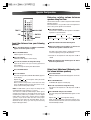
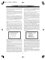
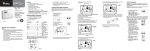
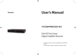
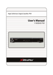
SPEAKER PLACEMENT
Dolby Digital identifies the use of Dolby Digital audio coding
for such consumer formats as DVD and DTV. As with film
sound, Dolby Digital can provide up to five full-range channels for left, center, and right screen channels, independent
left and right surround channels, and a sixth ( ".1") channel
for low-frequency effects.
Dolby Surround Pro Logic II is an improved matrix decoding
technology that provides better spatiality and directionality
on Dolby Surround program material; provides a convincing
three-dimensional soundfield on conventional stereo music
recordings; and is ideally suited to bring the surround experience to automotive sound. While conventional surround
programming is fully compatible with Dolby Surround Pro
Logic II decoders, soundtracks will be able to be encoded
specifically to take full advantage of Pro Logic II playback,
including separate left and right surround channels. (Such
material is also compatible with conventional Pro Logic
decoders.)
Dolby Digital EX creates six full-bandwidth output channels
from 5.1-channel sources. This is done using a matrix
decoder that drives three surround channels from the two
in the original recording. For best results, Dolby Digital EX
should be used with movies soundtracks recorded with
Dolby Digital Surround EX.
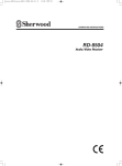
The ideal surround speaker system for this unit is 7-speaker systems, using front left and right speakers, a center
speaker, surround left and right speakers, surround back
left and right speakers, and a subwoofer.
For best results we recommend that all front speakers be
of the same type, with identical or similar driver units. This
will deliver smooth pans across the front sound stage as
the action moves from side to side.
Your center channel speaker is very important as over 80 %
of the dialog from a typical motion picture emanates from
the center channel.
It should possess similar sonic characteristics to the main
speakers. Surround channel speakers need not be identical to the front channel speakers, but they should be of
high quality.
The surround center speaker is useful for playback of
Dolby Digital Surround EX or DTS-ES. One of the benefits of
both Dolby Digital and DTS is that surround channels are
discrete full range, while they were frequency limited in
earlier "Pro Logic" type systems.
Bass effects are an important part of home theater.
For optimal enjoyment a subwoofer should be used as it is
optimized for low frequency reproduction. If you have full
range front speakers, however, they may be used in place
of a subwoofer with proper setting of the switches in the
menu system.
Surround
Back Left
Surround Left
Subwoofer
Front Left
About Dolby Pro Logic IIx
Dolby Pro Logic IIx technology delivers a natural and
immersing 7.1-channel listening experience to the home
theater environment. A product of Dolby's expertise in surround sound and matrix decoding technologies, Dolby Pro
Logic IIx is a complete surround sound solution that maximizes the entertainment experience from stereo as well as
5.1-channel encoded sources.
Front Center
0
22
150
30
135
Surround 110
Back Right
Surround Right
Front Right
90
Front left and right speakers
We recommend to set the front L and R speakers with 4560 degrees from the listening position.
Center speaker
Align the front line of the center speaker with the front L/R
speakers. Or place the center speaker a little backward
from the line.
Surround left and right speakers
When the LR-8500 is used in surround operation, the preferred location for surround speakers are on the side walls
of the room, at or slightly behind the listening position.
The center of the speaker should face into the room.
-6-
Connections
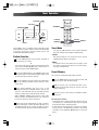
Surround back speakers
Surround back speakers are required when a full 7.1-channel system is installed.
Speakers should be placed on a rear wall, behind the listening position.
The center of the speaker should face into the room.
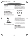
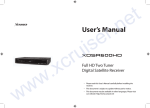
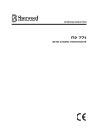
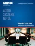
CONNECTING SPEAKER WIRE
1. Strip away approx. 10 mm of wire insulation.
2. Twist the bared wire ends tight, to prevent short circuits.
3. Loosen the knob by turning it counterclockwise.
4. Insert the bare part of the wire into the hole in side of
each terminal.
5. Tighten the knob by turning it clockwise to secure the
wire.
Subwoofer
We recommend using a subwoofer to have maximum bass
effect. Subwoofer bears only low frequency range so you
can place it any where in the room.
1.
2.
10 mm
3.
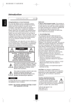
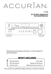
HEIGHT OF THE SPEAKER UNITS
4.
5.
Front left and right speakers, and a center speaker
Align the tweeters and mid-range drivers on the three front
speakers at the same height, as best as possible.
Surround left and right speakers, and surround back
speaker
Place the surround left, right and surround back speakers
higher than your ears by about 70cm -1m.
Also place the speakers at the same height, as best as possible.
Caution:
• Be sure to use speakers with the specified impedance as
shown on the rear panel of this unit.
• To prevent damage to circuitry, do not let the bare speaker wires touch each other and do not let them touch any
metal part of this unit.
• Do not touch the speaker terminals when the power is on.
It may cause you to receive an electric shocks.
• Do not connect more than one speaker cable to one
speaker terminal. Doing so may damage this unit.
70cm
1m
Note:
• Be sure to connect the positive and negative cables for
the speaker properly. If they are miss connected, the signal phase will be reversed and the signal quality will be
corrupted.
Note:
• Use magnetically-shielded speakers for front left, right
and the center speakers when the speakers are installed
near the TV and the TV is a monitor type.
CONNECTING A SUBWOOFER
Use the PRE OUT SUBWOOFER jack to connect a powered
subwoofer (power amplifier built in ).
If your subwoofer is a passive type (power amplifier is not
built in), connect a monaural power amplifier to the PRE
OUT SUBWOOFER jack and connect the subwoofer to the
amplifier.
-7-
Connections
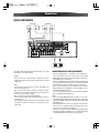
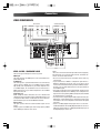
SPEAKERS, PRE OUT, AC OUTLET, RS-232C
(OPTIONAL)
POWERED
SUBWOOFER
SURROUND
CENTER
RIGHT
LEFT
RIGHT
ZONE II AUDIO
OUTPUT
RC-232C
AC OUTLET AC INPUT
RIGHT
LEFT
FRONT
RIGHT
LEFT
SURROUND
BACK
ZONE II SPEAKER OUTPUTS
PRE OUT ( SUB WOOFER ) jack
Use this jack to connect a powered sub-woofer or
passive sub-woofer with a power amplifier
(OPTIONAL) .
Surround Back/ZONE II Speaker Outputs:
These speaker terminals are normally used to
power the surround back left/surround back right
speakers in a 7.1-channel system. However, they
may also be used to power the speakers in a second zone. which will receive the output selected
for a ZONE II SPEAKER system. To change the
output fed to these terminals from the default of
the Surround Back speakers to the ZONE II
SPEAKER Output, you must change a setting in
the ZONE II SETUP of the OSD system. See page
30 for more information on configuring this speaker output. For ZONE II SPEAKER use, connect the
brown and black SBL terminals to the red and
black connections on the left remote zone speaker and connect the tan and black SBR terminals to
the red and black terminals on the right remote
zone speaker.
Power cord (AC INPUT)
Be sure to connect the power cord to an AC outlet
which supplies the correct voltage.
Hold the power plug when plugging or unplugging
the power cord.
AC OUTLET (SWITCHED)
This outlet is only active when the receiver is
turned on.
Caution:
Make sure that the total power consumption of all
equipment connected to the outlets on the receiver does not exceed 100 watts.
ZONE II AUDIO OUTPUT
RS-232C
Connect these jacks to the optional external audio
power amplifier and video distribution system that
delivers the source selected for ZONE II distribution.
The RS-232C port may also be used in the future to
update the operating software of the LR-8500 so
that it will be able to support new digital audio formats and the like as they are introduced.
-8-
Connections
AUDIO COMPONENTS
CD PLAYER
AUDIO
OUT
R
L
DIGITAL
OUT
TAPE DECK
AUDIO
IN
R
L
AUDIO
OUT
R
L
DIGITAL
OUT
DIGITAL
IN
DVD RECORDER
The output audio signal from the TAPE OUT jack is the same
signal which is currently selected.
CONNECTING DIGITAL AUDIO COMPONENTS
• There are 6 digital inputs, 3 coaxial jacks and 3 optical jacks,
on the rear panel. You can use these jacks to input PCM,
Dolby Digital and DTS bitstream signals from a CD, DVD, or
other digital source components.
• There is one digital output coaxial jack and one optical output
jack on the rear panel. These jacks can be connected to a CD
recorder, DVD recorder, or a MD deck inputs, respectively.
• Refer to the instructions for each component. To setup the
digital audio format of DVD player, or other digital source's
connected to digital input jacks.
• You can designate the input for each digital input/output
jacks according to your component.
Caution:
• Do not connect this unit and other components to mains
power until all connections between components have been
completed.
Notes:
• Insert all plugs and connectors securely. Incomplete connections may make noise.
• Be sure to connect the left and right channels properly.
Red connectors are for the R (right) channel, and white connectors are for the L (left) channel.
• Be sure to connect input and output properly.
• Refer to the instructions for each component that is connected to this unit.
• Do not bind audio/video connection cables with power cords
and speaker cables this will result in generating a hum or
other noise.
Notes:
• There is no Dolby Digital RF input jack. Please use an external RF demodulator Dolby Digital decoder when connecting
the Dolby Digital RF output jack of the video disc player to the
digital input jack.
• The digital signal jacks on this unit conform to the EIA standard. If you use a cable that does not conform to this standard, this unit may not function properly.
• Each type of audio jack works independently. Signals input
through the digital and analog jacks are output through the
corresponding digital and analog jacks, respectively.
-9-
Connections
VIDEO COMPONENTS
DVD PLAYER
AUDIO
OUT
R
L
COMPONENT
VIDEO OUT
Y CB/PB CR/PR
DIGITAL
OUT
VIDEO PROJECTOR
VIDEO
OUT
COMPONENT
VIDEO IN
S-VIDEO
OUT
Y CB/PB CR/PR
R
L
IN
R
S-VIDEO
IN
L
OUT
AUDIO
OUT IN
VIDEO
IN OUT
S-VIDEO
VCR
VIDEO, S-VIDEO , COMPONENT JACKS
There are 3 types of video jacks on the rear panel.
VIDEO jack
The video signal for the VIDEO jacks is the conventional composite video signal.
S-VIDEO jack
The video signal is separated into luminance (Y) and color (C)
signals for the S-VIDEO jack. The S-VIDEO signals enables
high-quality color reproduction. If your video component has
an S-VIDEO output, we recommend to use it. Connect the SVIDEO output jack on your video component to the S-VIDEO
input jack on this unit.
Component jack
Make component video connections to a TV or monitor with
component inputs to produce higher quality video images. Use
a component video cable or 3 video cords to connect the component video out jacks on the LR-8500 to the monitor.
Video convert
The input signals S-video are converted video signals can be
output.
Priority is given to S-VIDEO jack when having input by VIDEO
and S-VIDEO jack from the same source.
Notes:
• Be sure to connect the left and right audio channels properly.
Red connectors are for the R (right) channel, and white connectors are the for L (left) channel.
• Be sure to connect the inputs and outputs of the video signals properly.
• If you connect the S-VIDEO or component signal to the SVIDEO or component jack on this unit, it is not necessary to
connect the conventional video signal to the VIDEO (composite) jack. If you use both video inputs, this unit gives priority to
the S-VIDEO signal.
• Each type of video jack works independently. Signals input to
the VIDEO (composite) and S-VIDEO jacks or component are
output to the corresponding VIDEO (composite) and S-VIDEO
or component jacks, respectively.
• You may need to setup the digital audio output format of your
DVD player, or other digital source components. Refer to the
instructions of the each component connected to the digital
input jacks.
• There is no Dolby Digital RF input jack. Please use an external RF demodulator with a Dolby Digital decoder to connect a
video disc player which has a Dolby Digital RF output jack to
the digital input jack on this unit.
- 10 -
Connections
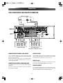
VIDEO COMPONENTS AND ADVANCED CONNECTING
SATELLITE TUNER
AUDIO
OUT
R
L
DIGITAL
OUT
VIDEO
OUT
REMOTE IR
IN/OUT PUT
ZONE II IR
INPUT
CENTER
CENTER
L
L
R
R
SUB
SURR.
FRONT SURR. WOOFER BACK
POWER AMPLIFIER
SUB
SURR.
FRONT SURR. WOOFER BACK
DVD AUDIO PLAYER
or
SACD MULTI CHANNEL PLAYER
CONNECTING MULTI CHANNEL AUDIO SOURCE
REMOTE IR INPUT
The 7.1 CH DIRECT INPUT jacks are for multichannel audio
source such as a SACD multichannel player, DVD audio
player or external decoder.
If you use these jacks, switch on the 7.1 CH DIRECT INPUT
and set the 7.1 CH DIRECT INPUT level by using the 7.1
channel input level menu.
If the LR-8500's front-panel IR sensor is blocked due to cabinet
doors or other obstructions, an external IR sensor may be
used. Connect the output of the sensor to this jack.
ZONE II IR Input
Connect the output of an IR sensor in a remote room to this
jack to operate the LR-8500's ZONE II control system.
CONNECTING AN EXTERNAL POWER AMPLIFIER
The PREOUT jacks are for connecting external power
amplifiers.
Be sure to connect each speaker to the corresponding
external power amplifier.
REMOTE IR OUTPUT
This connection permits the IR sensor in the receiver to serve
other remote controlled devices. Connect this jack to the "IR
IN" jack on LUXMAN (or other compatible) equipment.
- 11 -
Connections
CONNECTING THE ANTENNA TERMINALS
AM external
antenna
AM loop
antenna
FM antenna
FM external
antenna
CONNECTING THE SUPPLIED ANTENNAS
ASSEMBLING THE AM LOOP ANTENNA
1. Release the vinyl tie and take out the connection
line.
2. Bend the base part in the reverse direction.
3. Insert the hook at the bottom of the loop part into
the slot at the base part.
Connecting the supplied FM antenna
The supplied FM antenna is for indoor use only.
During use, extend the antenna and move it in various directions
until the clearest signal is received.
Fix it with push pins or similar implements in the position that will
cause the least amount of distortion.
If you experience poor reception quality, an outdoor antenna
may improve the quality.
Connecting the supplied AM loop antenna
The supplied AM loop antenna is for indoor use only.
Set it in the direction and position it to where you receive the
clearest sound. Put it as far away as possible from the unit, televisions, speaker cables, and power cords.
If you experience poor reception quality, an outdoor antenna
may improve the quality.
1. Press and hold down the lever of the AM antenna terminal.
2. Insert the bare wire into the antenna terminal.
3. Release the lever.
CONNECTING AN FM OUTDOOR ANTENNA
4. Place the antenna on stable surface.
Notes:
• Keep the antenna away from noise sources (neon signs, busy
roads, etc.).
• Do not put the antenna close to power lines. Keep it well away
from power lines, transformers, etc.
• To avoid the risk of lightning and electrical shock, grounding is
necessary.
CONNECTING AN AM OUTDOOR ANTENNA
An outdoor antenna will be more effective if it is stretched horizontally above a window or outside.
Notes:
• Do not remove the AM loop antenna.
• To avoid the risk of lightning and electrical shock, grounding is
necessary.
- 12 -
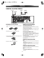
Control Functions
Front Panel
1
2
4
6
8
3
7
9
10
5
11
12
14
1 Main Power Switch
15
13
16
17
18
9 Surround Mode selector (n/6 )
Press this button to turn the unit standby or off.
2 Power Indicator
This LED Lights amber when the unit is in the standby
mode to signal that the unit is ready to be turn on, when
the unit is in operation, the indicator is blue.
3 PHONES/SETUP MIC
- This jack may be used to listen to the LR-8500's output
through a pair of headphones.
The speakers will automatically be turned off when the
headphone jack is in use.
- When configuring your system using ROOM AUTO
SETUP, the calibration microphone should be plugged
into this jack using the supplied adaptor that converts the
small mini-plug at the end of the microphone's cord to a
1/4"plug.
4 SOURCE (6/n )
Use these to select inputs. Also, these buttons used
power on switch when main power switch "ON" press
these buttons to turn on the unit.
5 AM/FM
Use this to switch between AM and FM bands.
6 Remote Sensor
When operating the remote control unit, point it toward
the remote sensor.
7 Display
When the unit on, the current status of the unit is displayed.
8 Surround Mode Group selector
Press this button to select the top-level group of surround
modes.
Each press of the button will select the current or last
used mode in each of the surround mode.
10
11
12
13
14
15
16
17
18
- 13 -
Press these buttons to select from among the available
surround mode options for the mode group and if the
input source is digital or analog.
MENU
Press repeatedly to select TONE MODE, CHANNEL Level,
Digital Input, Speaker Setup, Distance Adjust.
SELECT (n/6 )
When configuring the MENU settings, use these buttons
to select from available choice.
ENTER
When marking choices during the setup and configuration process, press this button to enter the desired setting.
TUN/PRE (6/n )
In Tuner mode, use these to tune in station.
T.MODE
Press this button to select Auto or Manual tuning.
VOLUME
Turn this knob to adjust the master volume.
OPT 4 Digital Input Jack
Connect the optical digital audio output of an audio or
video product to this jack.
VIDEO Input Jacks
These jacks may be used for temporary connection to the
composite or S-Video output of video games, camcorders
or other portable video products.
AUDIO Input Jacks
These audio jacks may be used for temporary connection
to video games or portable audio players.
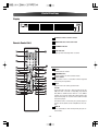
Control Functions
Display
1 Illuminates when a station is tuned.
2 STEREO indicates in the tuner mode.
Remote Control Unit
3 RDS MODE indicator
1
4 SLEEP indicator
33
Lights up when the sleep timer is active.
2
3
31
4
32
5
1 POWER
30
System power on and off.
6
29
7
2 FUNCTION buttons
8
Use these buttons to select function modes.
28
3 Numeric buttons
27
9
10
These buttons serve as a 10 button numeric keypad to
enter tuner preset positions.
4 TEST-T
26
11
25
12
24
13
- Output test tone for setting speaker levels.
23
TV / VID
22
14
15
21
- This button does not have a direct function on the LR8500, but when used with a compatibly programmed
VCR, DVD or satellite receiver that has a "TV / VIDEO"
function, pressing this button will switch between the
output of the player or receiver and the external video
input to that player.
20
16
17
18
19
Consult the owner's manual for your specific player or
receiver for the details of how it implements this function.
5 SURR. M
Press repeatedly to select the top-level group of surround modes.
- 14 -
Control Functions
6 SURR (v/^)
17 REPEAT
A-B
Press this button to select from among the available
surround mode options for the mode group selected.
- To repeat a specific section on a disc. (DVD only)
7 CH.
1/ALL
- Press to select CHANNEL LEVEL. (AMP only)
- To repeat chapter, track, title, disc(s). (DVD only)
TOP MENU
18 PROGRAM
- Press to call up the top menu. (DVD only)
Press to programming DVDs, CDs, Video CDs and
MP3. (DVD only)
8 DIRECTION
19 OPEN / CLOSE
- Use to more through the options on menu screens.
9 SPEAKER
Opens or close the disc tray. (DVD only)
- Press this button to begin to process of configuring
this unit's bass management system for use with the
type of speakers used in your system.
20 CLEAR
Removes a track number on the program menu. (DVD only)
21 SUB TITLE
RETURN
Select a subtitle language. (DVD only)
- Use to go one menu back(current setting are maintained). (DVD only)
22 AUDIO
Selects different audio languages available in the DVD
disc. (DVD only)
10 DIMMER
Press to adjust the brightness of the front display.
23 MEMO
11 TONE
- In Tuner mode to program preset radio stations.
- This button used Bass/Treble control.
RDS
TIME DISPLAY
- This function is used display information that is broadcasted by FM stations.
- Use this button to display time information about the
currently playing disc. (DVD only)
SKIP (.//)
12 TUNING UP/DOWN
- When playing discs, press . to go back to the
beginning of the current chapter / track and / to
advance to the next chapter / track. (DVD only)
- When the tuner is in use, these buttons will tune up or
down through the selected frequency band.
K Record
24 TUN-M
- Press to start normal recording. (DVD only)
- Switches from tuning to (manual or auto) tuning mode.
NTSC/PAL
PAUSE(J)
- Use this button to select NTSC, PAL or MULTI to match
your TV standard. (DVD only)
- Press to pause playback of a disc. (DVD only)
25 DIRECT
H STOP
- Press this button when the tuner is in use to start the
sequence for direct entry of a station's frequency.
- Press to stop playback. (DVD only)
13 PRESET UP/ DOWN
PLAY (t)
- Press to select a tuner preset channel.
- Press to start or resume playback. (DVD only)
SEARCH(m/,)
26 NIGHT
- During playback, these buttons are used for fast forward and fast reverse. (DVD only)
14 ANGLE
Selects a DVD camera angle if available. (DVD only)
15 ZOOM
- Press this button to activate the night mode. This mode
is available in specially encoded digital sources, and it
preserves dialogue(center channel) intelligibility at
low volume levels.
SLEEP
Enlarges the DVD Audio image. (DVD only)
- Press to set the sleep timer.
16 GUI
SLOW( - , +)
- Press to watch a disc with a slower speed. (DVD only)
Brings up the ON-SCREEN display. (DVD only)
- 15 -
Control Functions
ZONE II Remote Control Unit
27 DELAY
- Press this button to begin the process for setting the
delay times used LR-8500 when processing surround
sound or to compensate for video-to-audio delays
caused by the use of digital sources or video displays.
1
SET UP
8
- Enter or exit the system setup menu. (DVD only)
2
28 ENTER
7
Press to enter setting.
29 DIGITAL
3
- Press this button to assign one of the digital inputs to a
source
9
MENU
- Access the menu on a DVD disc. (DVD only)
4
30 OSD
- Press this button to activate the ON-Screen
Display(OSD) system used to set up.
6
5
- Select to NTSC or PAL (press this button for more than
3 seconds).
31 VOL (^/v)
Press to adjust volume.
32 MULTI
1 POWER
Press to select ZONE II ON/OFF, ZONE II INPUT and
ZONE II Volume.
33 MUTE
Press to activate the mute function.
When used in the room where the LR-8500 is located,
press this button to place the unit in Standby. When it
is used in a remote room with a sensor that is connected to the ZONE II IR Input jack, this button turns
the ZONE II system on and off.
2 AMP
Press this button to turn on the LR-8500. The input in
use when the unit was last on will be selected.
3 AM/FM Tuner Select Button
Press this button to select the Tuner as the input to
the ZONE II system. Press it again to change between
the AM and FM bands.
4 TUNING Up/Down
When this remote is used in the same room as the LR8500, these buttons may be used to change the frequency of tuner.
5 PRESET Up/Down
When the LR-8500's tuner is selected as the input
source, these buttons will move up or down through
the list of stations that have been stored in the preset
memory.
6 Volume Up/Down Buttons
When used in the room where the LR-8500 is located,
press this button to raise or lower the volume in that
room. When used in a remote room with a sensor that
- 16 -
Control Functions
Basic Operations 1
is connected to the ZONE II IR Input jack, this button
will raise or lower the volume in the remote room.
SELECT
SOURCE
VOLUME
7 INPUT Selectors
When the LR-8500 is off, press one of these buttons to
select a specific input and turn the unit on. When the
unit is already in use, pressing one of these buttons
will change the input.
8 MUTE
When used in the room where the LR-8500 is located,
press this button to temporarily silence the unit. When
it is used in a remote room with a sensor that is connected to the ZONE II IR Input jack, this button will
temporarily silence the feed to the remote room only.
Press the button again to return to the previous volume level.
STANDBY/ON
MENU
ENTER
DIGITAL
9 TUN-M
Switches from tuning to (manual or auto) tuning mode.
NOTES:
1 Press the STANDBY/ON button.
• The ZONE II remote may be used in either the same room
where the LR-8500 is located, or it may be used in a separate room with an optional infrared sensor that is connected to the LR-8500's ZONE II IR Input jack. When it is
used in the same room as the LR-8500, it will control the
functions of the LR-8500 or any compatible LUXMAN
products in that room. When it is used in a separate room
via a sensor connected to the ZONE II IR Input jack, the
button for Power, Input Source, Volume and Mute will
control the source and volume for the second zone, as
connected to the ZONE II Audio Output jacks. (See page
30 for complete information on using the ZONE II system.)
2 Select a source by pressing the SOURCE (5/b) button
repeatedly.
DVD
CD
TUNER
TAPE
7.1 CH DIRECT IN
VIDEO 1
VIDEO 2
AUX 1
AUX 2
3 Press DIGITAL button and press the 5orb button
repeatedly to select one of the digital inputs or the analog input for any source.
or
1. Press the MENU button on the front panel.
2. Each time the SELECT(5orb) button is pressed until
"DIGITAL INPUT" displayed on the front panel.
3. Press the ENTER button.
4. Each time the SELECT(5orb) button is pressed to
select you desired input.
3
4 Play the source, and gradually turn up the volume to
the required level with the VOLUME control.
- 17 -
Basic Operations 2
STANDBY/ON
SELECT
SOURCE
A
VOLUME B
MUTE C
VOLUME B
ENTER
MENU ENTER
D SURROUND MODE
GROUP SELECTOR
G TONE
SURROUND MODE
SELECTOR
SLEEP F
E
A SOURCE (6/n )
F Sleep Timer Function
Press to select input sources.
This function allows you to preprogram the receiver to
switch its own power off automatically. You can then enjoy
the audio/video system for a specified amount of time without having to worry about turning the unit off later.
Each press of the SLEEP button changes the time indication by 10 minutes.
B VOLUME knob
To control the overall listening level, turn the MASTER VOLUME knob or press the VOLUME buttons (+/–) on the
remote control unit.
C MUTE
To mute the sound temporarily, press the MUTE button.
Press the MUTE button again to restore the sound. If you
change the volume during the muting, the muting will be
canceled.
While muting is engaged, the MUTE indicator will flicker.
To let the remaining time (until power off) appear on the
display while the sleep timer is engaged, press the SLEEP
button once.
G TONE Control
1 Press the TONE button or press the MENU button and
D Surround Mode Group Selector
Press this button to select the top-level group of surround
modes.
Each press of the button will select the current or last used
mode in each of the surround mode groups.
ENTER button on the front panel in serial order.
"TONE IN" appears on the front panel's display.
2 Press the ENTER button.
"BASS ADJUST" appears on display.
E Surround Mode Selector
3 Press the 5/b button to select "BASS ADJUST" or "TRE-
Press this button to select from among the available surround mode options for the mode group selected.
BLE ADJUST" or press the SELECT(n/6) button and press
the ENTER button on the front panel.
• To adjust the level of low frequency sound range, select
"BASS ADJUST".
• To adjust the level of high frequency sound range, select
"TREBLE ADJUST"
4 Press the 5/b buttons of remote control unit or the
SELECT(n/6) button to change the setting. The level can
be adjusted in 1 dB steps from -10 to +10.
- 18 -
Surround Mode
Night Mode
One of the most important features of the LR-8500 is its
ability to reproduce a full multichannel surround sound
field from digital sources, analog matrix surroundencoded programs and standard stereo programs.
Surround modes may be changed at any time by using
either the front panel or remote controller.
In may listening situations, you may find loud passages
objectionable. Adjusting this setting allows you to compress the sounds into a range that you may find more
suitable for a particular listening situation. Dolby Digital
satisfies these needs through the dynamic range controlling. Select one of the followings to fit the individual
listening situation of the audience.
1 Press the SURR.M button (or the SURR.M button on
the remote controller) from the front panel until the
desired major surround mode group such as Dolby or
DTS is selected to select a new surround mode.
2 Press the SURR. SEL(n/6) button (or the SURR(v/^)
on the remote controller) repeatedly until choose the
specific individual.
• The Dolby Digital. Dolby Digital EX and DTS 5.1, DTSES Matrix and DTS-ES Discrete modes may only be
selected when a digital input is in use.
• The Dolby Pro Logic llx modes are available only
when the LR-8500 has been configured for 6.1/7.1
operation by configuring the Surround Back speakers as either "Large" or "Small"
1 The Night mode may be engaged when a Dolby
Digital DVD is playing by pressing the NIGHT button.
2 Press the 5/b buttons to select either the middle
range of full-compression versions of the Night
mode.
MAX:
Audio with fully compressed dynamic range.
MID:
Audio with partially compressed dynamic range.
OFF:
Audio with uncompressed dynamic range. Select this
when you don't want to use the night mode.
• When the 7.1 CH direct inputs are in use there is no
surround processing, as these inputs take the analog
output signals from an optional, external DVD-Audio
or SACD player, or another source device and carry
them straight through to the volume control without
any further digital processing.
• This function is effective only when playing back a
DVD disc recorded with Dolby Digital. This control
has no effect on other discs.
• To listen to a program in traditional two-channel
stereo, using the front left and front right speakers
only (plus the subwoofer, if installed and configured).
NOTE: Once a program has been encoded with matrix
surround information, it retains the surround information as long as the program is broadcast in stereo.
Thus, movies with surround sound may be decoded
via any of the analog surround modes such as Dolby
Pro Logic ll Movie or DTS Neo:6 Cinema, when they
are broadcast via conventional TV stations, cable,
pay-TV and satellite transmission. In addition, a growing number of made-for-television programs, sports
broadcasts, radio dramas and music CDs are also
recorded in surround sound.
- 19 -
SURR.M
SURR
NIGHT
ZONE II Operation
When operation the LR-8500 from a remote room location where an IR sensor link has been connected to
the LR-8500's rear-panel ZONE II IR Input you may use
either the main remote control or the ZONE II remote
controller.
To activate the feed to the remote room, while you are
main listening room where the LR-8500 is located,
NOTE:
• When the ZONE II system is turned on, the input
selected using the ZONE II menu will be fed to the
ZONE II Audio Outputs on the rear panel. The volume
will be as set in the previous selection, although it may
also be adjusted using an optional IR sensor and the
ZONE II remote in the remote location, or on the
optional audio power amplifier connected to the ZONE
II Audio Outputs.
1 Press the MULTI button on the main remote con-
troller and then press the ENTER button to turn the
ZONE II on or off.
2 Press the 5/b button to select " ZONE II INPUT" or "
ZONE II Volume" and then press the ENTER button.
3 Press the 5/b button repeatedly until the desired
input source or level. The level can be adjust in 1dB
steps from -80 to +10.
• Even when the LR-8500 is turned off in the main room,
the ZONE II system may be turned on the any time by
pressing any of the Selector buttons on the ZONE II
remote controller in the remote room. When the ZONE
II system is activated, you may turn it off from the
remote room location by pressing the Power Off
Button on the remote. The ZONE II system may only be
turned off using the MULTI button in the main room if
the LR-8500 is turned on.
- 20 -
Speaker Configuration
SPEAKER FRONT
SPEAKER
SIZE
SMALL
CENTER
SPEAKER
LARGE
FRONT L 9.0 M
SMALL
SURR
SPEAKER
SMALL
SBACK
SPEAKER
SMALL
WOOFER
SPEAKER
LEF
LARGE
LARGE
LARGE
LEF+FRONT
NONE
NONE
NONE
NONE
CENTER 9.0 M
FRONT R 9.0 M
SURR R 9.0 M
SBACK R 9.0 M
SBACK L 9.0 M
SURR L 9.0 M
WOOFER 9.0 M
DELAY 80mS
SPEAKER FRONT L FRONT L 0.0 M CENTER CENTER 0.0 M FRONT R FRONT R 0.0 M SURR R SURR R 0.0 M SBACK R SBACK R 0.0 M SBACK L SBACK L 0.0 M SURR L SURR L 0.0 M WOOFER WOOFER 0.0 M A/V SYNC DELAY 00mS
DELAY DISTANCE
DISTANCE
DISTANCE
DISTANCE
DISTANCE
DISTANCE
DISTANCE
DELAY
DISTANCE
FL +10dB
CEN +10dB
FR +10dB
SR +10dB
SBR +10dB
SBL +10dB
SL +10dB
S-W +10dB
CHANNEL FRONT L FL 0dB CENTER CEN 0dB FRONT R FR 0dB SURR R SR 0dB SBACK R SBR 0dB SBACK L SBL 0dB SURR L SL 0dB WOOFER S-W 0dB
LEVEL
LEVEL
LEVEL
LEVEL
LEVEL
LEVEL
LEVEL
LEVEL
LEVEL
(CH LEVEL)
FL -10dB
CEN -10dB
FR -10dB
SR -10dB
SBR -10dB
SBL -10dB
SL -10dB
S-W -10dB
: Press the tbutton.
: Press the 5orbbutton.
round mode for 7.1 channel (such as DOLBY PRO
LOGIC IIx MUSIC or MOVIE, etc).
POWER
3 Press the SPEAKER button.
"FRONT SPEAKER" appears on the front panel's display.
SURR.M
ENTER
4 Press the ENTER button.
"FRONT LARGE" or "FRONT SMALL" appears on the
display.
SPEAKER
It is important to perform speaker configuration prior to
using the surround sound decoder.
This allows the unit to sense the available speakers and
automatically select decoding modes. It is possible to
receive multi-channel surround sound without a center
speaker, but for best results with Dolby Pro Logic IIx
and Dolby Digital decoding, at least 5 speakers (Left,
Center, Right, Left Rear and Right Rear) should be used.
5 Press the 5/b buttons to change the setting.
6 Press the ENTER button.
The setting is saved in memory.
8 Press the 5 button.
< When no action is taken for 10 seconds, the Speaker
Setup mode will be cancelled.
Size of Speakers
1 Press the POWER button to turn the unit on.
2 Press the SURR.M button and select another sur-
- 21 -
The next configuration (CENTER) appears on the display.
Repeat step 4 to 8 to set other configurations.
When all the configurations have been finished,
press the SPEAKER button (or leave the unit for 5
seconds) to exit the Speaker Setup mode.
Speaker Configuration
Balancing relative volume between
speakers using Test Tone
The test tone function is useful to adjust the relative volume
between speakers.
Once the balance is set, you don't have to change the balance as long as the speakers aren't moved.
TEST-T
CH.
1 Press the TEST-T button.
VOLUME
The test tone is emitted from each speaker in the following order at 2-second intervals.
ENTER
FL(Front Left)
DELAY
CEN(Center)
FR(Front Right)
SL
SBL
SBR
SR
S-W
(Sub Woofer) (Surround Left) (Surround Back Left) (Surround Back Right) (Surround Right)
Input the distance from your listening
position
1 Press the DELAY button to "FRONT L DISTANCE"
2 Adjust the volume to the normal listening level.
3 Adjust the volume of each speakers so that the test
tone from each speakers sounds the same.
appears on the front panel's display.
The level of the speaker which is emitting the test tone
can be changed by pressing the 5/b buttons.
2 Press the ENTER button.
"FRONT" appears on the display.
< The level can be adjusted in 1 dB steps from -10 dB to
+10 dB.
3 Press the t button.
"FRONT L 3.O M" appears on the display.
4 When the setting has been finished, press the TEST-T
button to stop the test tone.
4 Press the 5/b buttons to change the setting.
Input the distance from your listening position to
front speakers.
You can change the setting from 0.0 to 9.0 M.
5 Press the ENTER button.
Output Level Adjustment (Balancing relative volume between speakers)
6 Press the 5 button.
1 Press the CH. button.
The next configuration (CENTER DISTANCE) appears
on the display.
Repeat step 2 to 6 to change the setting for center
and surround speakers.
When all the configurations have been finished,
press the DELAY button (or leave the unit for 8 seconds) to exit the Delay Adjust mode.
NOTE: LR-8500 allows you to adjust the delay for the
combined output of all speakers as a group.
This feature is called A/V SYNC Delay it allows you to
compensate for delays to the video image that may be
caused by the processing in products such as digital
video display, video scalers, digital cable or satellite
systems, or personal video recorders with proper
adjustment of the setting for A/V SYNC Delay, you can
eliminate the loss of lip sync that may be caused by
Digital video applications.
"FRONT L LEVEL" (Level of Front Left) appears on the display.
2 Press the ENTER button.
"FL LEVEL 0 dB" appears on the display.
3 Press the 5/b buttons to change the setting.
The level can be adjusted in 1 dB steps from -10 dB to
+10 dB.
4 Press the ENTER and press the 5 button.
- 22 -
The next configuration (CENTER LEVEL) appears on the
display.
Repeat step 2 to 4 to change other settings.
When all the configurations have been finished, press
the CH. button (or leave the unit for 10 seconds) to exit
the CH Level Adjust mode.
Tuner Operation
TUN/PRE
SELECT
NUMERIC
SOURCE
TUNING
PRESET
AM/FM
T.MODE
The LR-8500's tuner is capable of tuning AM, FM and FM
Stereo broadcast stations. Stations may be tuned manually,
or they may be stored as favorite station presets and
recalled from a 50-position memory.
Station Selection
1 Press the AM/FM button on the remote controller to
select the tuner as an input
or
The tuner may be selected from the front panel by either
pressing the SOURCE (6/n) buttons until the tuner is
active or by pressing the AM/FM button.
2 Pressing the AM/FM button or the AM/FM button on the
front panel again to switch between AM and FM so that
the desired frequency band is selected.
3 Press the T.MODE on the front panel (or the TUN-M but-
ton on the remote controller) to select manual or automatic tuning.
• Select "MAUNAL TUNING" and each press of the TUNING(v/^) button (or TUN/PRE button). The frequency
increases or decreases by one increment.
5 Stations may also be tuned directly. To enter a station's
frequency directly, first select the AM or FM. Next, press
the DIRECT button on the remote controller and enter
the station frequency by pressing the Numeric buttons.
TUN-M
MEMO
DIRECT
Tuner-Mode
Pressing the TUN-M button on the remote controller
alternates between Stereo mode and Mono mode.
- STEREO
FM stereo broadcasts are received in stereo and the
STEREO indicator lights in the display.
- MONO
To compensate for weak FM stereo reception, select
this mode. Reception will now be forced monaural,
reducing unwanted noise.
Preset Memory
You can preset a maximum of 50 favorite channels.
1 Press the MEMO button. The two underscore lines will
appear at the far right side of the display.
2 Within 5 seconds, press the Numeric buttons corre-
sponding to the location where you wish to store this
station's frequency.
4 Select "AUTO TUNING" and each press of the
TUNING(v/^) button (or TUN/PRE button). Then put the
tuner in a scan mode that seek the next higher or lower
frequency station with acceptable signal strength.
AM/FM
3 Repeat the process after tuning any additional stations
to be preset.
Recalling Preset Stations
• To manually select a station previously entered in the preset memory, press the Numeric buttons that correspond
to the desired station's memory location.
• To manually tune through the list of stored preset stations
one by one, press the PRESET(v/^) button or the remote
controller or the TUN/PRE (6/n) button on the front
panel.
- 23 -
RDS (Radio Data System)
(Remote Controller Only)
RDS (PTY)
NEWS
RDS is a broadcasting service which allows stations to
send additional information along with the regular radio
program signal. RDS can be received only in FM band.
Every time the RDS button is pressed, the mode is
changed as follows:
PS (Program Service Name)
When you select PS, "PS" is displayed, and in 4 seconds, the program service name will be displayed. If
there is no PS data in the station, the frequency will
be displayed.
PTY (Program Type)
When you select PTY with the RDS MODE button,
"PTY" will blink for about 4 seconds. After 4 seconds,
the type of received PTY will be displayed.
CT (Clock Time)
When you select CT with the RDS MODE button, "CT"
will blink for about 4 seconds. After 4 seconds, the
clock time will be displayed.
RT
AFFAIRS
INFO
SPORT
EDUCATE
DRAMA
CULTURE
SCIENCE
VARIED
POP M
ROCK M
When you select RT with the RDS button, "RT" will
blink for about 4 second.
After 4 seconds, the data of received RT will be displayed.
If there is no RT data among received broadcasting,
RDS mode will be automatically switched to PS
mode.
EASY M
LIGHT M
CLASSICS
OTHER M
PTY
WEATHER
FINANCE
CHILDREN
SOCIAL
RELIGION
PHONE IN
PTY search
A station can be searched by this function.
1 Press the RDS button for more than 1.5 seconds.
Then "PTY SEARCH" will be shown in the display.
2 Press the PRESET UP/DOWN button to select to desired
PTY mode. (The program will blink.)
3 Press the TUNING button. (PTY search be ready)
When the PTY mode that you have selected is searched,
PTY search will stop and the PTY mode will be displayed.
If the same program type is not found during PTY
Search, it will stop at the beginning frequency.
If you want to cancel PTY search while searching, press
the RDS button. PTY search will stop and search mode
will be released automatically.
TRAVEL
LEISURE
JAZZ
COUNTRY
NATION
OLDIES
FOLK M
DOCUMENT
TEST
ALARM !
- 24 -
:brief announcements, events, public
opinion, reports, actual situations.
:a kind of suggestion including practical
announcements other than news, documents, discussion, analysis and so on.
:daily information or reference such as
weather forecast, consumer guide,
medical assistance and so on.
:sports related programs.
:educational and cultural information.
:all kinds of radio concert and serial
drama.
:all aspects of national or local culture
including religious events, philosophy,
social science, language, theatre, and
so on.
:programs on natural science and technology
:popular programs such as quiz, entertainment, private interview, comedy,
satire and so on.
:program on commercial, practical and
popular songs, and sale volume of
discs, etc.
:practical modern music generally composed and played by young musicians.
:popular music usually lasting for less
than 5 minutes.
:classical music, instrumental music,
chorus, and light music favored by
non-professionals.
:orchestra including great operas, symphony, chamber music and so on.
:other music styles(Rhythm & Blues,
Reggae, etc.)
:weather reports, forecast
:financial reports, commerce, trading
:children's programs
:social affairs
:religious programs
:program in which the public expresses
its view by phone.
:travel reports
:programs concerning recreational
activities
:jazz music
:country music
:national music
:music from the so-called golden of
popular music
:folk music
:documentaries
:a program notifying an emergency or a
natural disaster.
System Configuration
(OSD - On Screen Display)
Video Operations
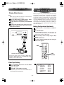
Playing Video Sources
Note:
When playing videos that feature surround sound,
refer to "Available Surround Modes".
1 Select the DVD, VIDEO 1, VIDEO 2, AUX 1, AUX 2
mode by pressing the SOURCE(6/n) button
2 Play the component corresponding to the FUNCTION
selected.
3 The picture from the video source can be seen on the
TV and the sound from the video source will be
heard from the speakers.
Before using the unit, you will probably want to change
the settings for most inputs so that they are properly
configured to reflect the use of digital or analog inputs,
the type of speakers installed and the surround mode
specifics of your home theater system. Remember that
since the LR-8500 memorizes the settings for each input
individually, you will need to make these adjustments
for each input used. However, once they are made, further adjustment is only required when system components are changed.
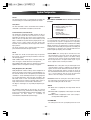
Making Configuration Adjustments
1 If another function is selected, press the AMP but-
Video Camera Connections
ton.
2 Press the OSD button.
The MAIN MENU will appear, and adjustments are
made from the individual menus. The menus will
remain on the screen for 20 seconds.
3 Select an item you want to change using the 5/b
buttons.
4 Press the ENTER button.
5 Press the t button repeatedly until the setting you
want to select appears.
AMP
OSD
ENTER
VCR, Video Camera Recorder, etc.
Connect the video camera recorder's AUDIO OUTPUT to the AUDIO (L)/(R) jacks and VIDEO OUT to the
VIDEO jack of the AUX 2 INPUT.
Video Tape Dubbing
2
1 Press the SOURCE(6/n) button to select the VIDEO
source to be recorded.
2 Playback the source.
3 Operate VID 1 or VID 2/VCR for recording.
Video/audio signals from the selected VIDEO source
can be dubbed to VID 2/VCR only.
- 25 -
MAIN MENU
FUNCTION
SURROUND
SPEAKER
DISTANCE
CH LEVEL
PREFERENCE
ZONE II
ROOM AUTO
SETUP
SETUP
SETUP
ADJUST
ADJUST
SETUP
SETUP
SETUP
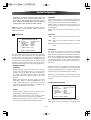
System Configuration
DTS 5.1
A FUNCTION SETUP
When the speaker configuration is set for 5.1-channel operation, the DTS 5.1 mode is available when DVD, audio-only
music or laser discs encoded with DTS data are played.
DTS 5.1 provides up to five separate main audio channels
and a special dedicated low-frequency channel.
FUNCTION SETUP
DVD
INPUT FUNC :
ANALOG
DIGITAL IN :
DIGITAL POLLING : NO
DTS-ES 6.1 Matrix, DTS-ES 6.1 Discrete
BACK TO MAIN MENU
You can select associate one of the digital inputs with the
selected input source. Some digital video input sources,
such as a cable box or HDTV set-top, may change between
analog and digital outputs, depending on which channel is
in use. The LR-8500's Auto Polling feature allows you to
avoid losing the audio feed when this happens by permitting
both analog and digital connections to the same source on
the unit Digital audio is the default, and the unit will automatically switch to the analog audio if the digital audio
stream stops.
When the speaker configuration is set for 6.1/7.1 operation,
playback of a DTS-encoded program source will automatically trigger the selection of one of the two DTS-ES modes.
Newer discs with special DTS-ES discrete encoding will be
decoded to provide six discrete, full-bandwidth channels
plus a separate low-frequency channel. All other DTS discs
will be decoded using the DTS-ES Matrix mode, which creates a 6.1-channel sound field from the original 5.1-channel
soundtrack.
Dolby Pro Logic II (Movie, Music, Pro Logic)
DOLBY SURROUND
DTS
DSP SURROUND
STEREO
Dolby Pro Logic II is the latest version of Dolby Laboratory's
benchmark surround technology that decodes full-range,
discrete left, center right, right surround and left surround
channels from either matrix surround-encoded programs
and conventional stereo sources when an analog input is in
use. The Dolby Pro Logic II Movie mode is optimized for
movie soundtracks, while the Pro Logic II Music mode
should be used with musical selections. The Pro Logic
mode activates original Pro Logic processing for those who
prefer that presentation.
BACK TO MAIN MENU
DTS Neo:6 Cinema, DTS Neo:6 Music
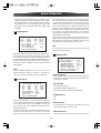
B SURROUND SETUP
SURROUND SETUP
Dolby Digital
Available only with digital input sources encoded with
Dolby Digital data. It provides up to five separate main
audio channels and a special dedicated low-frequency
effects (LFE) channel.
Dolby Digital EX
Available when the receiver is configured for 6.1/7.1-channel operation, Dolby Digital EX is the latest version of Dolby
Digital. When used with movies or other programs that have
special encoding, Dolby Digital EX reproduces specially
encoded soundtracks so that a full 6.1/7.1 sound field is
available. When the receiver is set for 6.1/7.1 operation and
a Dolby Digital signal is present, the EX mode is automatically selected. Even if specific EX encoding is not available
to provide the additional channel, the special algorithms
will derive a 6.1/7.1 output.
These two modes are available when any analog source is
playing to create a six-channel surround presentation from
conventional Matrix-encoded and traditional Stereo
sources. Select the Cinema version of Neo:6 when a program with any type of analog Matrix surround encoding is
present.
Select the Music version of Neo:6 for optimal processing
when a nonencoded, two-channel stereo program is being
played.
Dolby Virtual Speaker
Dolby Virtual Speaker uses advanced technology to simulate the sonic signature of a speaker location even when
there is no speaker physically present in that location. The
Reference ("REF") mode activates any missing speakers to
simulate a 5.1 presentation with accurate localization.
The Wide mode virtualizes the locations of the front-channel speakers to create a wider image and a more enveloping sound field. It is available no matter how many speakers
are present.
- 26 -
System Configuration
Theater
C DOLBY SURROUND
The Theater mode creates a sound field that resembles the
acoustic feeling of a standard live-performance theater.
When DOLBY SURROUND mode is selected, a menu will
be shown.
DOLBY SURR
Hall 1, Hall 2
MODE : DOLBY PRO LOGIC
CENTER WIDTH : ---DIMENSION : ---PANORAMA : ---NIGHT : OFF
UPSAMPLING : ---BACK TO MAIN MENU
The two Hall modes create sound fields that resemble a
small (Hall 1) and medium-sized (Hall 2) concert hall.
5-Channel Stereo, 7-Channel Stereo
This mode takes advantage of multiple speakers to place a
stereo signal at both the front and back of a room.
Depending on whether the unit has been configured for
either 5.1 or 6.1/7.1 operation, one of these modes, but not
both, is available at any time. Ideal for playing music in situations such as a party, it places the same signal at the
front-left and surround-left, and front-right and surroundright speakers.
The center channel is fed a summed mono mix of the inphase material of the left and right channels.
Stereo
This mode turns off all surround processing and presents
the pure left- and right-channel presentation of two-channel stereo programs.
PURE STEREO: When Audio input is selected analog, the
unit is in a "bypass" mode with no bass management.
DSP STEREO: When DSP Stereo is selected, the signal is
digitized and bass management settings are applied.
Dolby Headphone, DH 1, DH 2, DH 3
Dolby Headphone enables ordinary stereo headphones to
portray the sound of a five-speaker surround-playback system. The DH1 mode creates a headphone presentation that
resembles a small, well-damped room and is appropriate
for use with both movies and music-only recordings. The
DH2 mode creates a more acoustically live room particularly suited to music listening. The DH3 mode creates a
larger room, more like a concert hall or movie theater.
The Bypass mode bypasses any Dolby Headphone processing.
The choices on this menu include the selection of the actual surround mode, the selection of rear channel post-processing when the system is configured for 7.1 operation,
adjustments to the Night Mode when available with a Dolby
Digital soundtrack, the adjustment of special parameters
available when either Dolby Pro Logic ll Music or Dolby Pro
Logic llx Music is selected as the surround mode and control over digital upsampling, when available.
• Center Width: This setting adjusts the balance of the
vocal information in the front sound stage between the
center and front left/right speakers. The lower settings
spread the center channel sound more broadly into the
left and right channel s. A higher number (up to "7") produces a tighter center channel presentation.
• Dimension: This setting alters the perceived depth of the
surround field by creating a shallower presentation that
appears to move sounds toward the front of the room, or a
deeper presentation that appears to move the center of
the sound field toward the back of the room. The setting of
"O" is a neutral default, with the range of adjustment
shown as "R-3" for a deeper, rear-oriented sound.
• Panorama: Switch this setting on or off to add an enveloping wraparound presentation the increases the perception of sound along the sides of the room.
• NIGHT
OFF: When OFF is highlighted, the Night mode will not
function.
For additional information on the specifics of surround
modes and processing, information on Dolby modes may
be found at www.dolby.com/Consumer/Technologies, and
information on DTS modes is available at
www.dtsonline.com/home&car/overview.php.
MID: When MID is highlighted, a mild compression will be
applied.
MAX: When MAX is highlighted, a more severe compression algorithm will be applied.
• UPSAMPLING
The setting to turn the unit's upsampling feature on or off.
- 27 -
System Configuration
In normal use, this feature is turned off, which means that
digital sources are processed at their native sample rate.
For example, a 48kHz digital source will be processed at
48kHz. However, the LR-8500 allows you to upsample the
incoming 48kHz signals to 96kHz for added resolution.
SURROUND
LARGE: Select this when an external power amplifier and
large surround speakers are connected. Surround channels are output to the surround speakers at full range.
SMALL: Select this when the surround speakers are
rather small. Bass frequencies are output from your powered subwoofer.
NOTE: This feature is only available for the Dolby Pro Logic
ll-Music, Dolby Pro Logic ll-Movie, Dolby Pro Logic and
Dolby 3 Stereo modes.
NONE: Select this when no surround speakers are connected.
D SPEAKER SETUP
SURR BACK
LARGE: Select if the surround back speakers are large
sized.
SPEAKER SETUP
SMALL: Select if the surround back speakers are small
sized.
MODE
: SPEAKER SIZE
LEFT/RIGHT : SMALL
CENTER
: SMALL
SURROUND : SMALL
SURR BACK : SMALL
SUBWOOFER : SUB
NONE: Select if the surround back speakers are not connected.
SUBWOOFER
BACK TO MAIN MENU
LFE: Select if a subwoofer is connected to the LR-8500,
you have the option to have the front left/right
"main"speakers reproduce bass frequencies at all times,
and have the subwoofer operate only when the LR-8500 is
being used with a digital source that contains a dedicated
Low-Frequency Effects, or LFE, soundtrack. This allows
you to take advantage of the special bass created for certain movies.
This menu allows you to switch the menu to change either
the speaker size setting or the exact crossover point used
for that speaker group. For the first pass through the menu,
leave the setting at its default option of SPEAKER SIZE, and
then proceed as outlined below. Once the speaker choices
have been set, you may wish to return to this line to change
the option so that the crossover settings may be adjusted.
• SPEAKER SIZE MODE
LFE+FRONT: Select if a subwoofer is connected and you
wish to use it for bass reproduction is conjunction with
the main front left/right speakers, regardless of the type of
program source of Surround mode you are listening.
LEFT/RIGHT
LARGE: Select this when large front speakers are connected. Front channel materials are sent to the front
speakers at full range. When this setting is selected, less
bass signal is sent to the sub-woofer. Only use this setting
if you have adequate sized bass drivers in your front
speakers.
SMALL: Select this when the front speakers are rather
small. When "SMALL" is selected, SUBWOOFER is set to
"SUB" automatically, and bass frequencies of the front
channels are output from a subwoofer. So a powered subwoofer is indispensable for this setting.
NONE: Select if no subwoofer is connected to this unit. All
bass information will be routed to the front left/right
speakers.
• SPEAKER CROSS OVER MODE
CENTER
LARGE: Select this when a large center speaker is connected. Center channel is output at full range.
SMALL: Select this when the center speaker is rather
small. Bass frequencies are output from a subwoofer.
NONE: Select this when no center speaker is connected.
The center channel will be output from front speakers.
- 28 -
SPEAKER SETUP
MODE
LEFT/RIGHT
CENTER
SURROUND
SURR BACK
LFE
: SPK CROSS OVER
: 100Hz
: 100Hz
: 100Hz
: 100Hz
: LEFT/RIGHT
BACK TO MAIN MENU
The factory default setting for all speaker positions is
100Hz. If that setting is acceptable for all channels, then
System Configuration
no adjustments are needed and you may skip this section.
However, should you wish to change one of the settings.
The available choices at which point low-frequency information will be sent to the subwoofer, rather than to the
main speaker channel, are 40Hz, 60Hz, 80Hz, 100Hz, 120Hz
and 200Hz.
E DISTANCE ADJUST
Before beginning the output level adjustment process,
make certain that all speaker connections have been properly made. The system volume should be set to the level
that you will use during a typical listening session
DISTANCE ADJUST
FL
: 3.0 M
SBR
CEN : 3.0 M
SBL
FR
: 3.0 M
SL
SR
: 3.0 M
SUB
DELAY RESET : OFF
UNIT : METER
A / V SYNC DELAY
BACK TO MAIN MENU
: 3.0
: 3.0
: 3.0
: 3.0
there will be little or no sound in the surround channels.
This is because they are only used when a movie director
or sound mixer specifically places sound there to create
ambience or special effect, or to continue action from the
front of the room to the rear. When the output levels are
properly set, it is normal for surround speakers to operate
only occasionally. Artificially increasing the volume to the
rear speakers may destroy the illusion of an enveloping
sound field that duplicates the way you hear sound in a
movie theater or concert hall.
M
M
M
M
NOTE
: 0 mS
You can adjust channel level by pressing the TEST TONE
button on the remote control.
Due to the different distances between the listening position and each speaker position, the amount of time it takes
for sound to reach your ears from each channel is different.
You may compensate for this difference through the use of
the delay settings to adjust the timing for the speaker placement and acoustic conditions in your listening room or
home theater.
G PREFERENCE SETUP
PREFERENCE SETUP
DISPLAY TIME OUT
DISPLAY MODE
VOLUME DEFAULT
DEFAULT VOL SET
SEMI OSD TIME OUT
FULL OSD TIME OUT
DEFAULT SURR MODE
BACK TO MAIN MENU
NOTE
Once the DELAY ADJUST menu is on-screen, note that
default for distance settings is in meter. If your measurements are not in meter, change to feet at the UNIT line.
F CH LEVEL ADJUST
CH LEVEL ADJUST
FL
: 0dB
SBR :
CEN : 0dB
SBL :
FR
: 0dB
:
SL
SR
: 0dB
SUB :
LEVEL DEFAULT : OFF
TEST TONE SEQ : AUTO
TEST TONE
: OFF
BACK TO MAIN MENU
: OFF
: FULL
: OFF
: -25dB
:5
: 20
: ON
• DISPLAY TIME OUT
Select amount of time(3s~10s) that the display to fade out
of front panel. Select OFF if you do not wish to the front
panel displays fade out.
• DISPLAY MODE
FULL: Normal brightness.
HALF: Half the normal brightness level.
OFF: All of the front panel indicators will go dark.
0dB
0dB
0dB
0dB
• VOLUME DEFAULT
ON
OFF
Channel level adjustment is a key part of the configuration
of any surround sound product. It is particularly important
for a digital receiver such as the LR-8500, as correct outputs ensure that you hear soundtracks with proper directionality and intensity.
• DEFAULT VOL SET
Set the desired turn-on volume. This setting may not be
made with the regular volume controls.
Listeners are often confused about the operation of the surround channels. While some assume that sound should
always be coming from each speaker, most of the time
• SEMI OSD TIME OUT
- 29 -
The semi-OSD system places one-line message at the
System Configuration
video display screen whenever the volume, input source,
surround mode, tuner frequency or any of the configuration settings are changed.
the speakers used for the remote zone must be connected to the SURROUND BACK/ZONE II Speaker Outputs. The
volume for these speakers is set by the ZONE II SETUP.
Set to change the length of time that the semi-OSD displays remain on the screen.
I ROOM AUTO SETUP
• FULL OSD TIME OUT
The full-OSD menu system is used to simplify the setup
and adjustment of the LR-8500, using a series of on
screen menus. Set to change the length of time that fullOSD displays remain on the screen.
• DEFAULT SURR MODE
ON: Select if you wish to leave the default so that the
mode choice encoded in the disc is always used, no further action is needed. Simply leave the setting at the factory default of ON.
OFF: Select to set the unit so that it responds to the last
surround mode used when a Dolby Digital or DTS source
is playing.
H ZONE II SETUP
ZONE II SETUP
ZONE II
ZONE II IN
ZONE II VOL
SB AMPS
: OFF
: FM PRESET 01
: -25 dB
: SB SP
BACK TO MAIN MENU
Once the audio and IR link connections have been made,
the LR-8500 needs to be configured for ZONE II operation.
• ZONE II: Select to turn the system on and off.
• ZONE II IN: Select to the desired input to the ZONE II SETUP
• ZONE II VOL: Press the g/t buttons until the desired
volume level for the ZONE II SETUP is entered. Do not use
the regular volume control knob for this setting.
• SB AMPS: To change the setting so that the Surround
Back amplifiers are fed by the source selected through
the ZONE II SETUP. Remember that once this setting is
made, you will not be able to take advantage of any of the
6.1/7.1-channel decoding or processing modes, and that
- 30 -
The LR-8500 is one of the first receivers in its class to
offer automated speaker setup and system calibration.
This process greatly simplifies the installation of your
new receiver by using a series of test signals and the
power of an advanced digital signal processing system to
eliminate the need for manual adjustment of speaker
"size", crossover, delay and output level settings. With
ROOM AUTO SETUP your new receiver even alerts you to
errors in speaker connections that prevent a speaker
from functioning.
With ROOM AUTO SETUP you are able to calibrate your
system in a fraction of the time it would take to enter the
settings manually, and with results that rival those
achieved with expensive test equipment and time-consuming procedures.
The end result is a system calibration profile that enables
your new receiver to deliver the best possible sound, no
matter what type of speakers you have or what the
dimensions of your listening room.
We recommend that you take advantage of the precision
of ROOM AUTO SETUP to calibrate your system, but if
desire you may also make any of the configuration settings manually, or trim the settings provided by ROOM
AUTO SETUP by following the instructions.
If you wish to configure your manually, or if for some reason your ROOM AUTO SETUP microphone is unavailable,
you may still do so by following the instructions.
Step 1: ROOM AUTO SETUP requires that your listening
room have as little background noise as possible to avoid
interfering with the measurement of tones produced by
your LR-8500 during the setup procedure. Turn off all loud
fans, air conditioners and other equipment, and try to
avoid making any noise during the process.
Step 2: The ROOM AUTO SETUP microphone should be
placed in either your usual listening position or, if there is
a large seating area, the center of the room, at the listeners' ear level. You may find it convenient to use a camera
tripod for stable placement of the ROOM AUTO SETUP
microphone at the correct height. The microphone
includes a threaded insert on the bottom for tripod
mounting.
Step 3: Plug the ROOM AUTO SETUP microphone into the
LR-8500's Headphone Jack, making certain that the miniplug to 1/4" phone plug adaptor supplied with the micro-
System Configuration
phone is firmly connected. The microphone cable is
approximately 6 m long, which should accommodate
most listening room situations.
If required, you may use an optional extension cable,
available at most electronics stores, for use in larger
rooms. However, we recommend that you avoid using
extension cords for the microphone cable, as they may
adversely affect the test results.
Step 4: Once the microphone is properly positioned and
plugged in, proceed to the ROOM AUTO SETUP menus by
first pressing the OSD Button to bring the MAIN MENU to
the screen. Next, press the 5/b Buttons to move the
onscreen cursor to the ROOM AUTO SETUP menu line.
Press the ENTER Button to move to the next screen.
Step 5: The first screen of the ROOM AUTO SETUP system will now appear to remind you to plug in the microphone.
If you have not already done so, plug the microphone into
the Headphone Jack as described in steps 2 and 3. When
you are ready to proceed, make certain that the cursor is
pointing to YES and press the ENTER Button. If you do not
wish to continue with the ROOM AUTO SETUP process,
press the g /t Buttons and then press the ENTER
Button to return to the MAIN MENU. Note that if you
attempt to move to the next menu without plugging in the
microphone, a reminder message will flash at the bottom
of the screen.
ask someone else to run the ROOM AUTO SETUP
process, or that you do not use ROOM AUTO SETUP and
enter the configuration settings manually.
Step 7: The WARNING screen will automatically be
replaced by the main ROOM AUTO SETUP menu.
While this screen is visible, you may start and stop the
calibration process, or monitor the progress of the measurements and view the results. When the screen first
appears, you will see AUTO START: STOP on the first line
of the menu list. To start the ROOM AUTO SETUP test
process, you must first tell the system how many speakers are in your system. To do that, choose one of these
two options:
• If your system includes a full complement of seven main
speakers (front left/center/front right/surround right/surround back right/surround back left/surround left) and a
subwoofer, press the g/t Navigation Buttons so that
7.1 CH appears to the right of AUTO START, and then
press the Set Button to start ROOM AUTO SETUP.
• If your system includes a traditional surround speaker
complement of five main speakers (front left/center/front
right/surround right/surround left) and a subwoofer, press
the g/t Buttons so that 5.1 CH appears to the right of
AUTO START, and then press the Set Button to start
ROOM AUTO SETUP. To stop the calibration process at
any time, press the 5/b Buttons to move the on-screen
cursors to the AUTO START line; press the g /t
Navigation Buttons.
ROOM AUTO SETUP
ROOM AUTO SETUP
Put the microphone at
the position you want
to listen and connect
AUTO START
: STOP
SPEAKER CHECK : ---SPEAKER DELAY : ---SPEAKER LEVEL : ---: ---SPEAKER SIZE
SPEAKER X-OVER : ---SAVE RESULTS : ---BACK TO MAIN MENU
Do you want to start
Room auto Setup?
YES
NO
Step 6: After entering YES to start the ROOM AUTO
SETUP system, you will next see a brief warning message, and the screen will then change to the main ROOM
AUTO SETUP menu.
The WARNING screen is a reminder that in order for the
system to perform accurate measurements, it is important that the listening room be as quiet as possible. After
5 seconds, the screen will change again to display the
main ROOM AUTO SETUP menu.
IMPORTANT NOTE: Anyone with hearing that is sensitive
to loud noises should leave the room at this point, or use
ear protection sufficient to reduce the noise level.
Inexpensive foam-style ear plugs, available at most drug
stores, may be used to reduce the sound level to a tolerable level. If you are uncomfortable with, or cannot tolerate, loud sounds and do not use some sort of ear protection, we strongly recommend that you leave the room and
Step 8: Once ROOM AUTO SETUP has been started, you
will hear test signals circulate among all of the speakers
as the system sets the master level, checks to see where
there are speakers, sets the distance measurement and
calculates delay time settings, sets the speaker "size",
and sets the speaker crossover point. During the measurement and calibration process, you may observe the
progress of the testing by reading the messages that
appear in the second line of the menu listing. When the
ROOM AUTO SETUP screen first appears, it contains a
series of dashes, but as the test and measurement proceeds, you will see the following messages as the individual measurements are taken:
• System Level: ADJUST VOLUME message will appear to
indicate that the system is setting the overall volume level
to the proper level as a prelude to testing the individual
channels.
- 31 -
System Configuration
During this test, you will see a message in the last line of
the menu screen change as the volume level is adjusted.
• Speaker Check: The system will circulate a test signal to
determine which channels have a speaker connected.
During this test, you will see the name of each channel
position displayed while a signal is sent to that speaker.
NOTE: While this test detects whether a speaker is connected to a particular output, it cannot determine
whether the speaker is in the correct position. (For example, it can tell whether a speaker is connected to the
Surround Right output, but it cannot tell whether the
speaker is on the right or left side of your listening room.)
For that reason, we strongly recommend that you try to
listen as the tone circulates, matching the name shown
for each channel to the location of the speaker. If a tone
is heard from a speaker position that does not match the
on-screen message, stop ROOM AUTO SETUP, exit the
menus, turn your receiver off and check for proper
speaker connections on the rear panel before resuming
the setup.
When this test is complete, YES will be shown to the right
of SPEAKER CHECK on the menu screen.
• Speaker Delay: This test will circulate the tones again as
the name of each channel is shown to measure the distance from the microphone to each speaker. The results
of these tests will be used to set the delay time settings
for each active speaker position. When this test is complete, a speaker-tomicrophone (listening position) distance will be shown to the right of SPEAKER DELAY line
on the menu screen.
• Speaker Level: This test circulates a test signal and measures the output from each active speaker position. The
results of the measurements are used to adjust the individual channel outputs as needed, so that they are identical. This is an essential element of ensuring that surround
sound fields are properly reproduced. If desired, you may
use the results of the automated testing as a baseline and
then make manual adjustments to trim the output levels to
your personal taste. When this test is complete, an output
level adjustment number will be shown to the right of
SPEAKER LEVEL line on the menu screen.
• Speaker Size: The measurements and calculations for
this test take place at the same time as the test signals
are circulated to calculate the output levels, and they are
used to determine whether the speakers in your system
are "large" or "small" for the purposes of bass management. (If desired, you may use the results of the automated testing as a baseline and then make manual adjustments to the speaker size settings on a source-independent basis.When this test is complete, an output level
adjustment number will be shown to the right of the
SPEAKER SIZE line on the menu screen.
• Speaker Crossover: The measurements and calculations
for this test take place at the same time as the test signal
is circulated to calculate the levels, and they are used to
determine the crossover setting for each speaker in your
system to create a seamless transition between the frequencies sent to your main speakers and subwoofer (if
available). If desired, you may use the results of the auto-
- 32 -
mated testing as a baseline and then make manual
adjustments to the crossover settings on a source-independent basis. When this test is complete, a crossover
frequency will be shown to the right of the SPEAKER XOVER line on the menu screen.
Step 9: When all measurements are successfully completed, the test signals will stop and a TEST DONE UNPLUG MIC message will appear in the second line of
the on-screen menu listings.
Unplug the microphone and store it in a safe place so that
it is available to recalibrate your system if needed due to
a change in speakers, preferred listening position, or a
major change in the room's furnishings (such as the addition of thick carpeting or plush furniture) that might
require different settings. To enter the settings to the
receiver's memory and return to the Master Menu, press
the 5/b Buttons so that the on-screen cursor is pointing
to RETURN TO MAIN MENU.
NOTE: If you wish to check the test results before exiting
the ROOM AUTO SETUP menu, press the 5/b Buttons
that the on-screen cursor is at the second line of the
menu listings, and then press the g/t Buttons to scroll
through the list of speaker positions. The data on each
line will also be entered into the listings on the individual
SPEAKER SETUP, DELAY ADJUST and CHANNEL
ADJUST menus once you exit ROOM AUTO SETUP.
Step 10: If the measurements are not successful due to a
missing or malfunctioning speaker, an ERROR message
and menu will appear.
The ROOM AUTO SETUP system is programmed to look
for speaker pairs at the front left/front right, surround
left/surround right and surround back left/surround back
right positions. If the tests to any of those three channel
pairs indicates that one, but not both of the speakers in
the pair is present, the menu will show NONE next to the
speaker position where the tests did not report back that
a speaker is present. Should this message appear, make
note of the suspect speaker location, exit all menus and
turn the receiver off.
Check all speaker wire connections and then rerun
ROOM AUTO SETUP.
ERROR
FL
CEN
FR
SR
: YES
: YES
: YES
: NONE
SBR
SBL
SL
SUB
: YES
: YES
: YES
: YES
Please check speaker
or connections.
BACK TO MAIN MENU
When you have successfully completed the ROOM AUTO
SETUP process and made any needed adjustments to the
input and surround mode configurations, your receiver is
ready for use. If you do not wish to make any manual
adjustments to the settings, you may skip the rest of this
section and proceed to the Basic Operation section of
this manual to learn how to operate LR-8500. For those
situations where you may wish to make a change to the
settings entered by ROOM AUTO SETUP.
Controlling other Components Connected to the LR-8500
The LR-8500 is equipped with a powerful remote control not
only receiver's functions, but also most popular brands of
audio and video equipment, including CD players, cassette
decks, TV sets, cable boxes, VCRs, satellite receivers and
other home theater equipment.
B Manual Search Method
1 Turn on the unit that you wish to include in the LR-8500
remote controller.
2 Press the DEVICE button (VCR, SAT, TV) and the ENTER
button at the same time for 2 seconds until the
SEND/LEARN indicator blinks twice.
3 Press the 5 or b button. Each press will send out a
series of codes from the remote's built-in database.
4 When the unit being programed turns off, press the
ENTER button.
DEVICE
(Correct input: SEND/LEARN indicator blinks fourth.
Numeric
Incorrect input: SEND/LEARN indicator blinks once.)
C Code Check Method
Check if enter the 3-digit code number directly.
ENTER
1 While holding down the DEVICE button, press the
ENTER button for 2 seconds and then release both buttons
and then the SEND/LEARN indicator blinks twice.
2 Press the DIGITAL button.
3 The 3-digit code number blinks in order.
Example: If you enter '105'
1. 1: Indicator blinks once.
Learning a Pre-programming Code
2. 0: Indicator blinks tenth.
By following one of the methods below, you may program
the remote to operate a wide range of devices from other
manufacturers.
A Direct Code Entry Method
1 Find the 3-digit number for the brand name of the com-
ponent that you want to operate in the code list following pages. (See 34 page.)
2 Turn on the component that you want to operate.
3 While holding down the DEVICE button on the remote
controller that you want to program, press the ENTER
button for 2 seconds, and then release both buttons.
Then the SEND/LEARN indicator blinks twice.
4 Within 10 seconds, enter the 3-digit code number.
(Correct input: SEND/LEARN indicator blinks fourth.
Incorrect input: SEND/LEARN indicator blinks once.)
5 If the component does not operate properly, return to
step 3 and repeat the steps above.
- 33 -
3. 5: Indicator blinks fifth.
Programming the Remote
VCR Brand List
Brand
AKAI
ALBA
AMSTRAD
ANITSCH
ARC EN CIEL
ARISTONA
ASA
AWIA
BAIRD
BAUER. BOSCH
BLAUPUNKT
CODE No.
033
008
011
009
042
045
018
011
042
014
014
040
042
020
022
056
031
052
042
033
043
043
055
042
041
008
041
014
020
011
056
052
042
052
042
000
019
001
020
011
003
042
003
011
002
042
011
003
003
000
011
019
014
004
008
041
038
GRANADA
003
GRUNDIG
014
053
HANSEATIC
043
HARMAN-KARDON 004
HIFIVOX
042
HINARI
002
HITACHI
006
IMPERIAL
011
INGELEN
042
INGERSOL
027
ITT
005
052
056
013
052
020
021
BRANDT
ELECTRONIQUE
BRIONVEGA
BUSH
C.EDISON
CANON
CAPEHART
CGE
CONTINENTAL
EDISON
CRAIG
CURTIS MATHES
DAEWOO
DAYTRON
DECCA
DEGRAAF
DUAL
DUMONT
DYNATECH
EMERSON
FERGUSON
FIDELITY
FINLANDIA
FINLUX
FISHER
FUNAI
GE
GENERAL
GOLDSTAR
GOODMANS
GRAETZ
Brand
052 032
031 054
020
042
006
052
011
010
036
018
006
003
011
045 018
018
011
030
011
005
019 025
052 034
018
011
042
046
056
050 052
005
043
054
018
018
055 031
056
008
007
052
024
011
027
042
056
052
038
041
033
042
038
056 050
JENSEN
JVC
KENWOOD
KRIESLER
KUBA
LLOYD
LOEWE OPTA
LOGIK
LUXOR
MAGNADYNE
MAGNASONIC
MAGNAVOX
MARANTZ
MATUI
MEMOREX
METZ
MGA
MINERVA
MINOLTA
MITSUBISHI
MTC
MULTITECH
MURPHY
NAONIS
NATIONAL
NEC
NECKERMANN
NOGAMATIC
NOKIA
CODE No.
042
042
005
045
043
011
014
008
033
041
038
019
004
010
000
014
017
055
006
017
011
008
011
042
040
004
002
042
003
050
NORDMENDE
039
035
OPTONICA
045
ORION
002
OSAKI
011
OTTO VERAND
043
P. CINEMA
014
PALLADIUM
041
PANASONIC
023
PATHE MARCONI 042
PENTAX
006
PERDIO
011
PHILIPS
012
029
PHONOLA
014
PORTLAND
020
PROLINE
011
PYE
014
QUARTZ
005
QUELLE
002
RADIOLA
045
RADIOMARELLI
041
RCA
019
REALISTIC
000
045
REX
042
SABA
039
- 34 -
056
042
031
030
052
018
027
038
029
031
014
025
003
043
046
027
005
031
018 031
011 045
054 037
054
007
049
013
011
056
052
042
041
056
005
052
042
052
014
052
041
033
056
046
010
025
014
051
056
007
042 052
042 056
038
052 053
027
040
052
014
031
045
045
046 018
018
029 031
045
018
029 031
044
031
054
003
046
056
042
005
011 013
052
056
052 035
Programming the Remote
VCR Brand List
Brand
SAISHO
SALORA
SAMSUNG
SANSUI
SANYO
SBR
SCHAUB LORENZ
SCHNEIDER
SEI-SINUDYNE
SELECO
SENTRA
SHARP
SHINTOM
SIEMENS
SIERA
SINUDYNE
SONY
STERN
STS
SUNKAI
SYLVANIA
SYMPHONIC
TASHIKO
TATUNG
TEAC
TEKNIKA
TELEAVIA
TELEFUNKEN
TENOSAL
THOMSON
THORNFERGUSON
SAT Brand List
CODE No.
002
005
013
042
000
018
041
038
008
027
042
020
045
008
014
038
045
027
044
042
006
025
011
011
011
011
011
011
042
042
008
042
039
034
TOSHIBA
001
052
TOTELEVISION
013
UHER
042
ULTRA VOX
041
UNITECH
013
UNIVERSUM
041
URANYA
041
VECTOR
004
VICTOR
042
VIDITAL
041
WESTING HOUSE 041
WARDS
019
YAMAHA
004
ZANUSSI
042
ZENDER
052
ZOPPAS
042
010
017
019
025
Brand
027
032
003
029
042
005
025 038
056
050 052
011
045
031
056
052
046
105
048
043
055
031 054
016
052
026 028
031
015
056
017
017
042
042
056
056
052
052
056
052
042
036
042
030
052
056
017
014
043
042
056
052
056
ALBA
AMSTRAD
ARCON
ARISTONA
ASTRA
BLAUPUNKT
BUSH
CH.MASTER
CITY COM
DDC
DYNASAT
ECHOSTAR
EMME ESSE
FAIT
FERGUSON
FINLUX
FRACARRO
FTE
GOLDSTAR
GRAETZ
GROTHUSEN
GRUNDIG
HINARI
HIRSCHMANN
HITACHI
INGELEN
ITT
ITT-NOKIA
JERROLD
KATHREIN
KOSMOS
KRIESLER
LENCO
LUXOR
MAGAI
MARANTZ
MASPRO
MATSUSHITA
METZ
MINERVA
MULTISTAR
MURATO
NEC
NEIRU
NOKIA
NORSAT
PACE
PANASONIC
- 35 -
CODE No.
030
008
021
016
028
033
016
030
005
030
005
002
005
005
014
006
005
022
004
026
004
033
030
003
013
026
034
032
005
004
016
004
026
022
012
016
000
036
036
022
004
021
026
015
001
032
019
027
009
032
020
016
013
017 018
007
018
036
026
037
021
037
016
006
037
018
014
022
023
021
037
037
016
017
018
Programming the Remote
SAT Brand List
Brand
PHILIPS
PHONOLA
PROSAT
PYE
QUADRAL
QUELLE
RADIOLA
REDIFFUSION
SABA
SALORA
SAMSUNG
SAT PARTNER
SATPORTNER
SCHAUB LORENZ
SCHNEIDER
SIEMENS
SIERA
SILVA
SKY
STARCOM
STARSAT
TECHNISAT
TELEFUNKEN
TELESYSTEM
THORNFERGUSON
TRIAD
UNIDEN
UNITED CABLE
V TECHNOLOGY
VORTEC
ZENDER
TV Brand List
CODE No.
003
016
030
016
030
036
016
015
035
026
003
004
021
026
005
033
016
004
011
012
Brand
029
022
037
016
036
021
022
003
025
005
010
018
004
022
004
003
022
014
024
016
025
017
ADMIRAL
AKAI
ALBA
ALBIRAL
ALCATEL
AMSTRAD
ANAM
ARC EN CIEL
ARISTONA
CODE No.
050
093
068
116
022
021
000
028
099
149
ARTHUR MARTIN 053
123
ASA
050
ATLANTIC
099
AUDIOSONIC
054
AUSIND
053
AUTOVOX
099
069
BAIRD
083
BASICLINE
006
BAUR
011
BEKO
023
BLAUPUNKT
094
BRANDT
028
081
BRION VEGA
050
BRUNS
048
BSR
059
BUSH
033
CENTURY
098
CGE
016
136
CIHAN
065
CLARIVOX
048
CONDOR
099
CONTEC
087
CONTINENTAL
EDITION
028
081
CROSLEY
101
CROWN
147
CTC CLATRONIC 046
DAEWOO
089
DECCA
099
DEGRAAF
036
DIXI
049
DRYNATRON
049
DUAL
099
DUAL-TEC
096
DUMONT
046
ELBE
ELBIT
065
ELCIT
046
127
ELMAN
046
ELTA
090
EMERSON
098
- 36 -
134
049
039
049
078
139
125
055
111
123
043
050
145 081
019 142
117
128
057
120 122
144
055
019 057
049
100
039
102
040
111 114
043 145
050
110
068
101
101
132
124
050
124
074
079 136
079 132
039
040
043 145
050
109
060
063
115 118
132
057
116
073
103
050 109
113 134
116
111
090
141
099
050
016
097
132
132
050
Programming the Remote
TV Brand List
Brand
ERRES
EUROPHON
FERGUSON
FIDELITY
FINLUX
FISHER
FORGESTONE
FORMENTI
FORTRESS
FRABA
FRONTECH
FUJITSU
FUNAI
GBC
GEC
GELOSO
GOLDSTAR
GOODMANS
GORENJE
GREATZ
GRANADA
GRUNDIG
HANSEATIC
HANTAREX
HEMMERMANN
HIFIVOX
HINARI
HITACHI
HYPER
IMPERIAL
INGELEN
INNO HIT
INTERFUNK
IRRADIO
ITT
JVC
KTV
CODE No.
049
098
115
146
061
099
034
109
015
136
149
099
137
075
054
025
054
109
099
088
103
092
075
033
066
001
128
033
142
094
112
033
139
097
127
028
033
014
145
067
091
093
016
133
001
129
093
077
047
109
091
093
001
122
130
033
099
142
046
132
040
116
149
046
113
048
053
Brand
097
099 051
041
149
150 057
053
073
050
055 057
074 079
052 109
109
111 125
KAISUI
KARCHER
KENDO
KENNEDY
KORTING
KRIESLER
LENOIR
LOEWE OPTA
LOGIK
LUMA
LUXOR
MAGNADYNE
059
132
060
109
003
076
049
136
058
129
099
115
100
114
047
111
039
045
033
056
117
081
099
101
MAGNAFON
109
115 134
132
017
077
060
134 090
099 049
090
077
109
130
049
125
057
082
099
122 123
134
058 060
134
058 108
049 109
043
143
034
109
132
088
145
090
036
139
134
081
124
079 132
099
110
084
MARANTZ
MATSUI
McMICHAEL
MEMOREX
METZ
MINERVA
MISTRAL
MITSUBISHI
MIVAR
MULTITECH
MURPHY
MAONIS
NATIONAL
NEC
NECKERMANN
NEI
NIKKAI
NOBLEX
NOBLIKO
NOGAMATIC
NOKIA
058
130
098
090
049
142
109
134
097
122 128
NORDMENDE
099 143
050
123
145 058
128 129
143
140
123
134
053
058
128
135
077
105
148
083
OCEANIC
ONCEAS
OPTONICA
ORION
OSAKI
OSIO
OSUME
OTTO VERSAND
P.T ACTTRON
PAEL
PANASONIC
090
109
129
089
- 37 -
CODE No.
006
006
098
144
050
099
149
099
008
115
118
049
058
129
046
115
046
115
049
090
068
088
090
094
094
149
033
062
138
097
046
134
096
042
033
099
049
060
015
098
028
001
122
130
028
131
109
099
137
090
060
077
087
033
065
099
030
019
059
049
078
109
111
050
019 142
097
072
149
120
139
135
097
127
097
047
049 050
134
117
083
103
132
099
120 123
050 109
051 053
099
134
106
060 118
050
100
114
057
133
058 114
035
118
047
119
049 050
148 080
099
099
115
115
077
136
144
104
085
050
019
109
110 134
139
120 136
046
039
140
123
134
032
091
064
099
043
058
128
135
039
081
123
053
145
105
148
083
043
059
118
068 127
047
049
109 139
053
042
095
104 107
057
081
109
129
089
145
Programming the Remote
TV Brand List
Brand
CODE No.
Brand
109
099
060
016
124
009
099
148
099
099
149
020
121
111
126
116
132
030
079
010
049
149
053
049
078
049
101
132
013
050
078
109
050
050
136
018
019
088
111
019
145
091
098
124
098
049
099
148
QUASAR
046
QUELLE
047
055
113
074
RADIOLA
099
149
RADIOMARELLI
046
062
RANK
074
RBM
074
REDIFFUSION
062
REX
096
069
ROBOTRON
048
RTF
048
SABA
028
040
115
SAISHO
090
SALORA
053
123
SAMBERS
046
077
SAMPO
121
SAMSUNG
015
136
SANYO
001
048
054
SBR
049
SCHAUB LORENZ 001
128
SCHNEIDER
096
019
149
SEG
046
SEI
059
097
053
115 134
SILVER
SINGER
SINUDYNE
SONOKO
SONY
097
054
049
149
097
099
057
114
128
049
078
097
127
053
134
STERN
050
078
051
100
058
118
019 142
053
049
111
123
TANDBERG
TANDY
TASHIKO
TATUNG
050
019 142
103
132
050 109
PATHE CINEMA
PERDIO
PHILCO
PHILIPS
PHOENIX
PHONOLA
PIONEER
PRANDONIPRINCE
PREMIER
PRINCE
PROTECH
PYE
123
144
134
050
050
031
043
120
099
139
125
097
026
090
002
060
142
058
129
099
141
078
SELECO
109
024
142
SHARP
SIAREM
SICATEL
SIEMENS
SIERA
125
142
077
053
112
073
TEC
TELEAVIA
TELEFUNKEN
134
019
TELETECH
TELEVIDEON
TENSAI
THOMSON
141 110
THORNFERGUSON
032
097
086
118
117
128
051
037
050
091
119
120
135
053
039
145
081
068
122
083
115
TOCOM
TOSHIBA
TRANS
CONTINENTS
UHER
ULTRA VOX
099
054 077
005
113
136
148
109
130
049
109
132
033 044
118 071
UNIVERSUM
UNIVOX
VEGAVOX
VOXSON
WATSON
WATT RADIO
149
122
134
050
142
WEGA
WHITE
WESTINGHOUSE
YOKO
ZANUSSI
088
123
052
125
ZOPPAS
- 38 -
CODE No.
016
110
033
046
116
005
114
099
149
054
016
127
049
146
118
096
134
133
099
002
099
118
096
028
091
028
091
090
099
049
012
043
096
069
087
097
144
134
137
050
019 141
094
087
049
078
036
100 111
050
019 142
046
046
090
007
050
050
109
059 109
027
033 038
144
019
110 069
060
033
060
137
063
065 115
099
039
081
041
132
040
043 145
145
150 086
053
109
111 125
028
145
032
091
039 040
081
014
057
029
004
040
061
041
116
054 150
149 086
016
033
070 074
098
052
098
120
092
116
079
050
111
046
127
033
097
111
046
053
125
099
134
034
054
077
051
109 116
099
099
096
134
096
111
144
019
110 069
144
019
110 134
109 115
050 109
134
099
Troubleshooting
SYMPTOM
CAUSE
SOLUTION
Unit does not function when
Main Power Switch is
pushed
• No AC power
Display lights, but no sound
or picture
• Intermittent input connections
• Make certain AC power cord is plugged into a
live outlet.
• Check to see whether outlet is switch-controlled.
• Mute is on
• Make certain that all input and speaker connections are secure.
• Volume control is down
• Press Mute Button.
• Turn up volume control.
Unit turns on, but front-panel
display does not light up
• Display brightness is turned off
• Follow the instructions in the Display Mode (29
page) so that the display is set to FULL.
No sound from any speaker;
light around power switch is
red
• Amplifier is in protection mode due
to possible short
• Check speaker wire connections for shorts at
receiver and speaker ends.
• Amplifier is in protection mode due
to internal problems
• Contact your local LUXMAN service center.
No sound from surround or
center speakers
• Incorrect surround mode
• Select a mode other than Stereo.
• Input is monaural
• Incorrect configuration
• There is no surround information from mono
sources.
• Stereo or Mono program material
• Check speaker mode configuration.
• The surround decoder may not create centeror rear-channel information from nonencoded
programs.
Unit does not respond to
remote commands
• Weak batteries in remote
• Wrong device selected
• Press the FUNCTION buttons.
• Remote sensor is obscured
Intermittent buzzing in tuner
Letters flash in the channel
indicator display and digital
audio stops
• Change remote batteries.
• Local interference
• Make certain front-panel sensor is visible to
remote, or connect remote sensor.
• Move unit or antenna away from computers,
fluorescent lights, motors or other electrical
appliances.
• Digital audio feed paused
• Resume play for DVD.
• Check that Digital Input is selected.
- 39 -
Specifications
Amplifier Section
AM Tuner Section
Output Power
Power Output (20 Hz - 20 kHz, THD<0.07%, 8 ohms)
Front L&R
110 W / Ch
Center
110W / Ch
Surround L & R
110 W / Ch
Surround Back
110 W / Ch
Power Output (EIAJ, 1 kHz, 8 ohms)
Front L&R
140 W / Ch
Center
140 W / Ch
Surround L & R
140 W / Ch
Surround Back
140 W / Ch
Input Sensitivity/Impedance
Linear (High-Level)
240mV/47k ohms
Signal-to-Noise Ratio (IHF-A)
95dB
Surround System Adjacent Channel Separation
Pro Logic
40dB
Dolby Digital (AC-3)
55dB
DTS
55dB
Frequency Response
@ 1W (+0dB, -3dB)
10Hz - 100kHz
Tuning Range: 522 kHz – 1,620 kHz (9 kHz steps)
Usable Sensitivity: 55 dB/m
Total Harmonic Distortion: 0.8%
Signal-to-Noise Ratio: 40 dB
Video Section
Television Format
: PAL / NTSC
Input Level/Impedance : 1Vp-p/75 ohms
Output Level/Impedance : 1Vp-p/75 ohms
Video Frequency Response
(Composite and S-Video) : 10Hz-5.8MHz (-1dB)
Video Frequency Response
(Component Video)
: 10Hz-50MHz (-3dB)
General
Power Requirements:
AC 220-240 V~ , 50/60 Hz
Power Consumption:
Tone Control:
415W
AC Outlets:
BASS: ± 10 dB at 100 Hz
TREBLE: ± 10 dB at 10 kHz
Switched x , 100 W max.
Dimensions (W x H x D)
440 x 160 x 385 mm
Digital Audio Section
Weight (net): 14.1Kg
Standard Accessories:
Sampling Frequency: 32 kHz, 44.1 kHz, 48 kHz, 96 kHz
DIGITAL Input Level/Impedance:
OPTICAL : –15 dBm — –21 dBm
COAXIAL : 0.5 Vp-p / 75 ohms
AM Loop Antenna x 1
FM Antenna x 1
Remote Control Unit x 1
AAA-size Batteries x 2
Owner’s Manual x 1
Micro Phone x 1
Zone II Remote Control Unit x 1 (With Battery )
FM Tuner Section
(Without notes 100.1 MHz, 65 dBf)
Tuning Range:
87.5 MHz – 108.0 MHz (50 kHz steps)
Usable Sensitivity (IHF):
Mono : 11.2 dBf
50 dB Quieting Sensitivity:
Mono : 18.3 dBf
Stereo: 38.5 dBf
Capture Ratio: 2.0 dB
Image Rejection Ratio: 80 dB
AM Suppression Ratio: 55 dB
Total Harmonic Distortion (1 kHz):
Mono : 0.2%
Stereo: 0.3%
Frequency Response: 15 Hz – 16 kHz, +1/ –1.5 dB
Stereo Separation (1 kHz): 40 dB
Signal-to-Noise Ratio:
Mono : 70 dB
Stereo: 68 dB
* LINE means CD, TAPE, VIDEO 1, VIDEO 2, AUX 1, AUX
2, DVD.
* Manufactured under license from Dolby Laboratories.
"Dolby, "Pro Logic" and the Double-D symbol are
trademarks of Dolby Laboratories.
DTS, DTS Surround, DTS-ES and DTS Neo:6, DTS
96/24 are registered trademarks of Digital Theater
Systems, Inc.
< Improvements may result in specifications and features changing without notice.
< Illustrations may differ slightly from production models.
- 40 -
LUXMAN CORPORATION, JAPAN