1
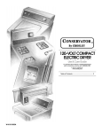
120-VOLT COMPACT ELECTRIC DRYER Use & Care Guide For questions about features, operation/performance parts, accessories or service, call: 1-800-253-1301. or visit our website at... www.crosley.com Table of Contents ................................................. 2 W10151585B TABLE OF CONTENTS DRYER SAFETY..............................................................................2 INSTALLATION INSTRUCTIONS ..................................................3 Tools and Parts ............................................................................3 Location Requirements................................................................4 Electrical Requirements ...............................................................5 Venting Requirements..................................................................5 Plan Vent System .........................................................................6 Install Vent System.......................................................................7 Install Cord Bracket and Casters.................................................7 Connect Vent................................................................................8 Complete Installation ...................................................................8 DRYER USE ....................................................................................9 Starting Your Dryer.......................................................................9 Stopping and Restarting ..............................................................9 Drying, Cycle, and Temperature Tips ........................................10 Cycles .........................................................................................10 DRYER CARE...............................................................................11 Cleaning the Dryer Location.......................................................11 Cleaning the Lint Screen ............................................................11 Cleaning the Dryer Interior .........................................................11 Removing Accumulated Lint......................................................11 Vacation and Moving Care.........................................................11 TROUBLESHOOTING ..................................................................12 Dryer Operation ..........................................................................12 Dryer Results ..............................................................................12 ASSISTANCE OR SERVICE .........................................................14 ACCESSORIES .............................................................................14 WARRANTY ..................................................................................15 DRYER SAFETY 2 INSTALLATION INSTRUCTIONS Parts needed Tools and Parts Tools needed Gather the required tools and parts before starting installation. Read and follow the instructions provided with any tools listed here. ■ Flat-blade screwdriver ■ Level ■ Adjustable wrench ■ Vent clamps ■ Caulking gun and compound (for installing new exhaust vent) ■ Tin snips (new vent installations) Check local codes, existing electrical supply and venting, and see “Venting Requirements” and “Electrical Requirements” before purchasing parts. ■ Mobile home installations require metal exhaust system hardware ■ Permanent installations require 4 dryer feet For information on ordering, please reference the “Assistance or Service” section. You can also contact the dealer from whom you purchased your dryer. Parts supplied Remove parts package from the dryer drum. Check that all parts listed are included. ■ Cycle Control (timer) knob ■ Cord brackets (2) ■ Push to Start button ■ Screws (2) ■ Casters (4) 3 Minimum spacing for recessed area and closet installation Location Requirements The following dimensions shown are for the minimum spacing allowed when the dryer is to be operated with, or without, the Stack Stand Kit. To purchase a Stack Stand Kit, see “Assistance or Service.” ■ Additional spacing should be considered for ease of installation and servicing. ■ Additional clearances might be required for wall, door, and floor moldings. ■ Additional spacing of 1" (25 mm) on all sides of the dryer is recommended to reduce noise transfer. ■ For closet installation with a door, minimum ventilation openings in the top and bottom of the door are required. Louvered doors with equivalent ventilation openings are acceptable. ■ Companion appliance spacing should also be considered. Recessed or closet installation - Dryer only 14"* (356 mm) You will need ■ A location that allows for proper exhaust installation. See “Venting Requirements.” ■ A 120-volt, 60-Hz., AC-only, 15- or 20-amp circuit. ■ A grounded electrical outlet located within 2 ft (610 mm) of either side of the dryer. See “Electrical Requirements.” ■ A sturdy floor to support the dryer weight (dryer and load) of 115 lbs (52 kg). The combined weight of a companion appliance should also be considered. ■ 18"* (457 mm) 3"* (76 mm) A A level floor with a maximum slope of 1" (25 mm) under entire dryer. Do not operate your dryer at temperatures below 45ºF (7ºC). At lower temperatures, the dryer might not shut off at the end of an automatic cycle. Drying times can be extended. The dryer must not be installed or stored in an area where it will be exposed to water and/or weather. Check code requirements. Some codes limit, or do not permit, installation of the dryer in garages, closets, mobile homes, or sleeping quarters. Contact your local building inspector. 1" (25 mm) B 1" (25 mm) A. Side view - closet or confined area B. Recessed area Recessed or closet installation - Stacked 3"* (76 mm) 3"* (76 mm) 12"* (305 mm) 48 in.2* (309.7 cm2 ) DRYER 12"* (305 mm) Installation Clearances The location must be large enough to allow the dryer door to open fully. 2 24 in. * (154.8 cm2) WASHER 3"* (76 mm) Dryer Dimensions 3 20 " *(527 mm) 4 1"* 1" (25 mm) (25 mm) 1" (25 mm) A B C A. Recessed area B. Side view - closet or confined area C. Closet door with vents 31"† (787 mm) Mobile Home - Additional Location Requirements This dryer is suitable for mobile home installations. The installation must conform to the Manufactured Home Construction and Safety Standard, Title 24 CFR, Part 3280 (formerly the Federal Standard for Mobile Home Construction and Safety, Title 245, HUD Part 280) or Standard CAN/CSA-Z240 MH. 23 7 8" (606 mm) †Height with caster is 32½" (826 mm) *Most installations require a minimum 5" (127 mm) clearance behind the dryer for the exhaust vent with elbows. See “Venting Requirements.” 4 Mobile home installations require: ■ Metal exhaust system hardware, which is available for purchase from your dealer. ■ Venting Requirements Special provisions must be made in mobile homes to introduce outside air into the dryer. The opening (such as a nearby window) should be at least twice as large as the dryer exhaust opening. Electrical Requirements WARNING: To reduce the risk of fire, this dryer MUST BE EXHAUSTED OUTDOORS. IMPORTANT: Observe all governing codes and ordinances. The dryer exhaust must not be connected into any gas vent, chimney, wall, ceiling, attic, crawlspace, or a concealed space of a building. If using an existing vent system ■ A 120-volt, 60-Hz., AC-only, 15- or 20-amp fused electrical supply is required. ■ A time-delay fuse or circuit breaker is recommended. Be sure fuse or circuit breaker matches the rating of your line. ■ Use a separate circuit serving only your dryer. ■ Do not use an extension cord. ■ Clean lint from the entire length of the system and make sure exhaust hood is not plugged with lint. ■ Replace any plastic or metal foil vent with rigid or flexible heavy metal vent. ■ Review Vent system chart. Modify existing vent system if necessary to achieve the best drying performance. Only rigid or flexible metal vent shall be used for exhausting. If this is a new vent system GROUNDING INSTRUCTIONS ■ For a grounded, cord-connected dryer: This dryer must be grounded. In the event of malfunction or breakdown, grounding will reduce the risk of electric shock by providing a path of least resistance for electric current. This dryer is equipped with a cord having an equipmentgrounding conductor and a grounding plug. The plug must be plugged into an appropriate outlet that is properly installed and grounded in accordance with all local codes and ordinances. Vent material ■ Use a heavy metal vent. Do not use plastic or metal foil vent. ■ 4" (102 mm) heavy metal exhaust vent and clamps must be used. WARNING: Improper connection of the equipmentgrounding conductor can result in a risk of electric shock. Check with a qualified electrician or service representative or personnel if you are in doubt as to whether the dryer is properly grounded. Do not modify the plug provided with the dryer: if it will not fit the outlet, have a proper outlet installed by a qualified electrician. SAVE THESE INSTRUCTIONS 4" (102 mm) heavy metal exhaust vent Rigid metal vent ■ For best drying performance, rigid metal vents are recommended. ■ Rigid metal vent is recommended to avoid crushing and kinking. Flexible metal vent ■ Flexible metal vents are acceptable only if accessible for cleaning. ■ Flexible metal vent must be fully extended and supported when the dryer is in its final location. ■ Remove excess flexible metal vent to avoid sagging and kinking that may result in reduced airflow and poor performance. 5 ■ Do not install flexible metal vent in enclosed walls, ceilings, or floors. ■ The total length of flexible metal vent should not exceed 7 3/4 ft (2.4 m) ■ Do not use an exhaust hood with a magnetic latch. Elbows 45° elbows provide better airflow than 90° elbows. Plan Vent System Choose your exhaust installation type Recommended exhaust installations Typical installations vent the dryer from the rear of the dryer. Good A Better A Clamps ■ Use clamps to seal all joints. ■ Exhaust vent must not be connected or secured with screws or other fastening devices that extend into the interior of the duct and catch lint. Do not use duct tape. B C Exhaust Recommended hood styles are shown here. B A. Exhaust hood B. Flexible metal or rigid metal vent C. Elbow Alternate installations for close clearances A 4" (102 mm) Venting systems come in many varieties. Select the type best for your installation. Two close-clearance installations are shown. Refer to the manufacturer’s instructions. 4" (102 mm) A. Louvered hood style B. Box hood style The angled hood style (shown here) is acceptable. 4" (102 mm) A 2½" (64 mm) ■ ■ An exhaust hood should cap the vent to keep rodents and insects from entering the home. Exhaust hood must be at least 12" (305 mm) from the ground or any object that may be in the path of the exhaust (such as flowers, rocks, bushes, snow line, etc.). A. Over-the-top installation (also available with one offset elbow) B. Periscope installation NOTE: The following kits for close clearance alternate installations are available for purchase. For information on ordering, see “Assistance or Service.” ■ Over-the-Top Installation: Part Number 4396028 6 B ■ Periscope Installation (for use with dryer vent to wall vent mismatch): Vent system chart Part Number 4396037 - for mismatch of 0" (0 mm) to 18" (457 mm) Number of 90º turns or elbows Type of vent Box or louvered hoods Angled hoods Part Number 4396011 - for mismatch of 18" (457 mm) to 29" (737 mm) 0 Rigid metal 36 ft (11 m) 26 ft (7.9 m) Part Number 4396014 - for mismatch of 29" (737 mm) to 50" (1.27 m) 1 Rigid metal 26 ft (7.9 m) 16 ft (4.9 m) 2 Rigid metal 16 ft (4.9 m) 6 ft (1.8 m) Special provisions for mobile home installations The exhaust vent must be securely fastened to a noncombustible portion of the mobile home structure and must not terminate beneath the mobile home. Terminate the exhaust vent outside. Determine vent path Install Vent System 1. Before installing the vent system, be sure to remove the wire exhaust guard that is located at the exhaust outlet. 2. Install exhaust hood. Use caulking compound to seal exterior wall opening around exhaust hood. 3. Connect vent to exhaust hood. Vent must fit inside exhaust hood. Secure vent to exhaust hood with 4" (102 mm) clamp. 4. Run vent to dryer location. Use the straightest path possible. See “Determine vent length.” Avoid 90º turns. Use clamps to seal all joints. Do not use duct tape, screws, or other fastening devices that extend into the interior of the vent to secure vent, because they can catch lint. ■ Select the route that will provide the straightest and most direct path outdoors. ■ Plan the installation to use the fewest number of elbows and turns. Install Cord Bracket and Casters ■ When using elbows or making turns, allow as much room as possible. Do not move dryer into its final location until the following steps have been performed. ■ Bend vent gradually to avoid kinking. ■ Use the fewest 90° turns possible. Determine vent length and elbows needed for best drying performance ■ Use the Vent system chart below to determine type of vent material and hood combinations acceptable to use. NOTE: Do not use vent runs longer than those specified in the Vent system chart. Exhaust systems longer than those specified will: ■ Shorten the life of the dryer. ■ Reduce performance, resulting in longer drying times and increased energy usage. Install cord bracket 1. Remove tape from power cord and rear panel. The Vent system chart provides venting requirements that will help to achieve the best drying performance. 7 2. Insert cord brackets into slotted holes in rear panel and secure with screws provided. A B C A. Cord bracket B. Slotted hole C. Screw NOTE: Power supply cord may be wrapped around the brackets for storage convenience when dryer is not in use. Install casters 1. Lay dryer on its side. 2. Use carton to avoid damage to dryer. Complete Installation 1. Check that all parts are now installed. If there is an extra part, go back through steps to see what was skipped. 2. Check that you have all of your tools. 3. Dispose of/recycle all packaging materials. 4. Check dryer’s final location. Be sure vent is not crushed or kinked. 5. Check that dryer is on a level surface. 6. Plug into a grounded 3 prong outlet. Turn power on. 7. Remove film on console and any tape remaining on dryer. Remove tape from the lint screen (located on inside back wall of dryer). 8. Read “Dryer Use.” 9. Wipe dryer drum interior thoroughly with a damp cloth to remove any dust. 10. To test the dryer, set the dryer on a full heat cycle (not an air cycle) for 20 minutes and start the dryer. If the dryer will not start, check the following: ■ Controls are set in a running or “On” position. ■ Push to Start button has been firmly pressed. ■ Dryer is plugged into a grounded 3 prong outlet. ■ Electrical supply is connected. ■ Household fuse is intact and tight, or circuit breaker has not tripped. ■ Dryer door is closed. 11. When the dryer has been running for 5 minutes, open the dryer door and feel for heat. If you feel heat, cancel cycle and close the door. If you do not feel heat, check the following: ■ Controls are set on a heated cycle, not an air cycle. NOTE: You may notice an odor when dryer is first heated. This odor is common when the heating element is first used. The odor will go away. 3. Screw casters into dryer base at four corners and tighten securely. 4. Set dryer upright. In doing so, be certain that dryer does not roll away from you. NOTE: Permanent installations require 4 dryer feet. See “Assistance or Service” section for information on ordering. Connect Vent 1. Using a 4" (102 mm) clamp, connect vent to exhaust outlet in dryer. If connecting to existing vent, make sure the vent is clean. Dryer vent must fit over dryer exhaust outlet and inside exhaust hood. Check that vent is secured to exhaust hood with a 4" (102 mm) clamp. 2. Move dryer into its final location. Avoid crushing or kinking vent. 3. (On gas models) Check that there are no kinks in the flexible gas line. 4. Once exhaust vent connection is made, remove corner posts and cardboard. 8 DRYER USE Starting Your Dryer Before using your dryer, wipe dryer drum with a damp cloth to remove dust from storing and shipping. 1. Load clothes loosely into dryer and close the door. Do not pack dryer. Allow space for clothes to tumble freely. 2. Turn Cycle Control knob to the recommended cycle for the type of load being dried. Use the Energy Preferred Automatic Setting (*) to dry most heavyweight and medium-weight loads. See “Drying, Cycle, and Temperature Tips.” 3. Press PUSH TO START button. Stopping and Restarting You can stop your dryer anytime during a cycle. To stop your dryer Open dryer door or turn Cycle Control knob to OFF. NOTE: The Cycle Control knob should point to an Off area when dryer is not in use. To restart your dryer 1. Close the door. 2. Select a new cycle and temperature (if desired). 3. Press PUSH TO START button. WARNING: To reduce the risk of fire, electric shock, or injury to persons, read the IMPORTANT SAFETY INSTRUCTIONS before operating this appliance. 9 Air Dry Cycle Drying, Cycle, and Temperature Tips Select the correct cycle and temperature for your load. Your dryer tumbles the load without heat during the last few minutes of all cycles to make the load easier to handle. Drying tips ■ Follow care label directions when they are available. ■ If desired, add a fabric softener sheet. Follow package instructions. ■ Remove load from the dryer as soon as tumbling stops to reduce wrinkling. This is especially important for permanent press, knits, and synthetic fabrics. Cycle and temperature tips Use this cycle for items that require drying without heat, such as rubber, plastic, and heat-sensitive fabrics. See the chart for examples of items that can be dried using an air cycle. Type of Load Time* Foam rubber—pillows, padded bras, stuffed toys Plastic—shower curtains, tablecloths Rubber-backed rugs Olefin, polypropylene, sheer nylon 20 - 30 20 - 30 40 - 50 10 - 20 *(Minutes). Reset cycle to complete drying, if needed. When using an air cycle ■ Check to see that coverings are securely stitched. ■ Dry most loads using the Energy Preferred Automatic Setting (*). ■ Shake and fluff pillows by hand periodically during cycle. ■ Use a no heat (air) setting for rubber, plastic, or heat-sensitive fabrics. ■ Dry item completely. Foam rubber pillows are slow to dry. ■ Line-dry bonded or laminated fabrics. Timed Dry Cycle NOTE: If you have questions about drying temperatures for various loads, refer to the care label directions. Cycles Use this cycle to complete drying if items are still damp after the automatic cycle. Timed Dry is also useful for: ■ Heavyweight items and work clothes that require a long drying time. ■ Lightweight items, such as lingerie, blouses, and knits that require a short drying time. For damp dry, turn the Cycle Control knob to 30 minutes or less. End of Cycle Signal The dryer sounds a signal to let you know when the cycle is finished. The signal is not adjustable and cannot be turned off. The signal is helpful when you are drying permanent press, synthetics, and other items that should be removed as soon as the dryer stops. Cycle Control knob Permanent Press This automatic cycle shuts off the dryer when the selected dryness is reached. The Cycle Control knob does not move until the load is almost dry. After the cool down, the knob automatically turns to an Off area and tumbling stops. Dry most loads using the Energy Preferred Automatic Setting (*). ■ If the load is drier than you like, select a setting closer to Less Dry the next time you dry a similar load. ■ If the load is not as dry as you like, complete drying using the Timed Drying cycle. The next time you dry a similar load, select a setting closer to More Dry. NOTE: Drying time with an automatic cycle varies according to the type of fabric and size of load. 10 DRYER CARE Cleaning the Dryer Location 3. Wet a nylon brush with hot water and liquid detergent. Scrub lint screen cover and body with the brush to remove residue buildup. Keep dryer area clear and free from items that would obstruct the flow of combustion and ventilation air. 4. Rinse with hot water. 5. Thoroughly dry lint screen body and cover with a clean towel. Replace in dryer. Cleaning the Dryer Interior To clean dryer drum Cleaning the Lint Screen Every load cleaning The lint screen is located inside the dryer drum, on the back wall. Clean it before each load. A screen blocked by lint can increase drying time. To clean 1. Open the door and pull the lint screen straight out. 1. Make a paste with powdered laundry detergent and very warm water. 2. Apply paste to a soft cloth. OR Apply a liquid, nonflammable household cleaner to the stained area and rub with a soft cloth until all excess dye is removed. 3. Wipe drum thoroughly with a damp cloth. 4. Tumble a load of clean cloths or towels to dry drum. NOTE: Garments that contain unstable dyes, such as denim blue jeans or brightly colored cotton items, may discolor the dryer interior. These stains are not harmful to your dryer and will not stain future loads of clothes. Dry unstable dye items inside out to avoid transfer of dye. Removing Accumulated Lint From Inside the Dryer Cabinet 2. Squeeze body of lint screen lightly while pulling off the cover. 3. Roll lint off the screen with your fingers. Do not rinse or wash screen to remove lint. Wet lint is hard to remove. 4. Replace cover on lint screen body. Push the lint screen firmly back into place and close the door. IMPORTANT: ■ Do not run the dryer with the lint screen loose, damaged, blocked, or missing. Doing so can cause overheating and damage to both the dryer and fabrics. As needed cleaning Laundry detergent and fabric softener residue can build up on the lint screen. This buildup can cause longer drying times for your clothes, or cause the dryer to stop before your load is completely dry. The screen is probably clogged if lint falls off the screen. Clean the lint screen with a nylon brush every 6 months, or more frequently, if it becomes clogged due to a residue buildup. To wash 1. Roll lint off the screen with your fingers. 2. Wet both the lint screen cover and body with hot water. Lint should be removed every 2 years, or more often, depending on dryer usage. Cleaning should be done by a qualified person. From the Exhaust Vent Lint should be removed every 2 years, or more often, depending on dryer usage. Vacation and Moving Care Vacation care Operate your dryer only when you are at home. If you will be on vacation or not using your dryer for an extended period of time, you should: 1. Unplug dryer or disconnect power. 2. Clean lint screen. See “Cleaning the Lint Screen.” Moving care 1. Unplug the power supply cord. 2. Make sure leveling legs are secure in dryer base. 3. Use tape to secure dryer door. 11 TROUBLESHOOTING First try the solutions suggested here to possibly avoid the cost of a service call... Dryer Operation Dryer Results Dryer will not run ■ Has a household fuse blown, or has a circuit breaker tripped? There may be 2 fuses or circuit breakers for the dryer. Check that both fuses are intact and tight, or that both circuit breakers have not tripped. Replace the fuse or reset the circuit breaker. If the problem continues, call an electrician. ■ Is the correct power supply available? This electric dryer requires 120-volt power supply. Check with a qualified electrician. ■ Was a regular fuse used? Use a time-delay fuse. ■ Is the dryer door firmly closed? ■ Was the PUSH TO START button firmly pressed? Clothes are not drying satisfactorily, drying times are too long, or load is too hot NOTE: The compact dryer operates at a lower wattage. Expect longer drying times. ■ Is the lint screen clogged with lint? Lint screen should be cleaned before each load. No heat ■ Has a household fuse blown, or has a circuit breaker tripped? The drum may be turning, but you may not have heat. Electric dryers use 2 fuses or circuit breakers. Replace the fuse or reset the circuit breaker. If the problem continues, call an electrician. Unusual sounds ■ Has the dryer had a period of non-use? If the dryer hasn’t been used for a while, there may be a thumping sound during the first few minutes of operation. ■ Is a coin, button, or paper clip caught between the drum and front or rear of the dryer? Check the front and rear edges of the drum for small objects. Clean out pockets before laundering. ■ Are the four legs installed, and is the dryer level front to back and side to side? The dryer may vibrate if not properly installed. See the Installation Instructions. ■ Is the clothing knotted or balled up? When balled up, the load will bounce, causing the dryer to vibrate. Separate the load items and restart the dryer. Timer does not noticeably advance ■ Is the dryer set to Timed or Air Dry? The timer moves slowly and continuously for the timed setting. ■ Is the dryer set to Automatic Drying? The timer moves only when the clothing is mostly dry. 12 ■ Is the exhaust vent or outside exhaust hood clogged with lint, restricting air movement? Run the dryer for 5-10 minutes. Hold your hand under the outside exhaust hood to check air movement. If you do not feel air movement, clean exhaust system of lint or replace exhaust vent with heavy metal or flexible metal vent. See “Venting Requirements.” ■ Are fabric softener sheets blocking the grille? Use only one fabric softener sheet, and use it only once. ■ Is the exhaust vent the correct length? Check that the exhaust vent is not too long or has too many turns. Long venting will increase drying times. See “Venting Requirements.” ■ Is the exhaust vent diameter the correct size? Use 4" (102 mm) diameter vent material. Lint on load ■ Is the lint screen clogged? Lint screen should be cleaned before each load. Stains on load or drum ■ Was dryer fabric softener properly used? Add dryer fabric softener sheets at the beginning of the cycle. Fabric softener sheets added to a partially dried load can stain your garments. Drum stains are caused by dyes in clothing (usually blue jeans). This will not transfer to other clothing. Loads are wrinkled ■ ■ Was the load removed from dryer at the end of the cycle? ■ Was the dryer tightly packed? Dry smaller loads that can tumble freely. Is the dryer located in a room with temperature below 45ºF (7ºC)? Proper operation of dryer cycles requires temperatures above 45ºF (7ºC). ■ Is the dryer located in a closet? Closet doors must have ventilation openings at the top and bottom of the door. The front of the dryer requires a minimum of 1" (25 mm) of airspace, and, for most installations, the rear of the dryer requires 5" (127 mm). See the Installation Instructions. ■ Has an air dry cycle been selected? Select the right cycle for the types of garments being dried. ■ Is the load too large and heavy to dry quickly? Separate the load to tumble freely. Odors ■ Have you recently been painting, staining, or varnishing in the area where your dryer is located? If so, ventilate the area. When the odors or fumes are gone from the area, rewash and dry the clothing. ■ Is the dryer being used for the first time? The new electric heating element may have an odor. The odor will be gone after the first cycle. 13 ASSISTANCE OR SERVICE Before calling for assistance or service, please check “Troubleshooting.” It may save you the cost of a service call. If you still need help, follow the instructions below. When calling, please know the purchase date and the complete model and serial number of your appliance. This information will help us to better respond to your request. ACCESSORIES Enhance your dryer with these premium accessories. For more high-quality items or to order, call 1-800-901-2042, or visit us at www.applianceaccessories.com. In Canada, call 1-800-807-6777 or visit us at www.whirlpoolparts.ca. Part Number Accessory 20-48KITRC 4 ft (1.2 m) gas line dryer connector installation kit PT220L 4 ft (1.2 m) dryer cord, 3-wire, 30 amp If you need replacement parts If you need to order replacement parts, we recommend that you only use Factory Service Parts. These parts will fit right and work right because they are made with the same precision used to build every new CROSLEY® appliance. To locate Factory Service Parts replacement parts in your area: Call our Customer eXperience Center or your nearest designated service center. For assistance or service Call the Customer eXperience Center at 1-800-253-1301. Our consultants provide assistance with: ■ Features and specifications on our full line of appliances ■ Installation information ■ Use and maintenance procedures ■ Accessory and repair parts sales ■ Specialized customer assistance (Spanish speaking, hearing impaired, limited vision, etc.) ■ Referrals to local dealers, repair parts distributors, and service companies Crosley designated service technicians are trained to fulfill the product warranty and provide after-warranty service, anywhere in the United States. To locate the Crosley designated service company in your area, you can also look in your telephone directory Yellow Pages. For further assistance If you need further assistance, you can write to us with any questions or concerns at: Crosley Distribution Center c/o Correspondence Dept. 675 North Main Street Winston-Salem, NC 27102-2111 Please include a daytime phone number in your correspondence. 14 PT400L 4 ft (1.2 m) dryer cord, 4-wire, 30 amp PT600L 6 ft (1.8 m) dryer cord, 4-wire, 30 amp 8212614 Dryer vent lint brush 31682 All-purpose appliance cleaner 1903WH Laundry supply storage cart 3404351 Drying rack - fits 29" (737 mm) Super Capacity, 6.5 cu. ft (0.18 cu. m) - side swing or hamper door 3406839 Drying rack - fits 29" (737 mm) Super Capacity Plus, 7.0 cu. ft (0.20 cu. m) - side swing door only 49971 Compact dryer stand - white 49572 LP gas conversion kit CROSLEY® CORPORATION LAUNDRY WARRANTY LIMITED WARRANTY For one year from the date of purchase, when this major appliance is operated and maintained according to instructions attached to or furnished with the product, Whirlpool Corporation or Whirlpool Canada LP (hereafter “Whirlpool”) will pay for factory specified parts and repair labor to correct defects in materials or workmanship that existed when this major appliance was purchased. Service must be provided by a Whirlpool designated service company. YOUR SOLE AND EXCLUSIVE REMEDY UNDER THIS LIMITED WARRANTY SHALL BE PRODUCT REPAIR AS PROVIDED HEREIN. This limited warranty is valid only in the United States or Canada and applies only when the major appliance is used in the country in which it was purchased. Proof of original purchase date is required to obtain service under this limited warranty. ITEMS EXCLUDED FROM WARRANTY This limited warranty does not cover: 1. Replacement parts or repair labor if this major appliance is used for other than normal, single-family household use or when it is used in a manner that is inconsistent to published user or operator instructions and/or installation instructions. 2. Service calls to correct the installation of your major appliance, to instruct you on how to use your major appliance, to replace or repair house fuses, or to correct house wiring or plumbing. 3. Service calls to repair or replace appliance light bulbs, air filters or water filters. Consumable parts are excluded from warranty coverage. 4. Damage resulting from accident, alteration, misuse, abuse, fire, flood, acts of God, improper installation, installation not in accordance with electrical or plumbing codes, or use of products not approved by Whirlpool. 5. Cosmetic damage, including scratches, dents, chips or other damage to the finish of your major appliance, unless such damage results from defects in materials or workmanship and is reported to Whirlpool within 30 days from the date of purchase. 6. Pick up and delivery. This major appliance is intended to be repaired in your home. 7. Repairs to parts or systems resulting from unauthorized modifications made to the appliance. 8. Expenses for travel and transportation for product service if your major appliance is located in a remote area where service by an authorized Whirlpool servicer is not available. 9. The removal and reinstallation of your major appliance if it is installed in an inaccessible location or is not installed in accordance with Whirlpool’s published installation instructions. 10. Replacement parts or repair labor on major appliances with original model/serial numbers that have been removed, altered, or cannot be easily determined. DISCLAIMER OF IMPLIED WARRANTIES IMPLIED WARRANTIES, INCLUDING ANY IMPLIED WARRANTY OF MERCHANTABILITY OR IMPLIED WARRANTY OF FITNESS FOR A PARTICULAR PURPOSE, ARE LIMITED TO ONE YEAR OR THE SHORTEST PERIOD ALLOWED BY LAW. Some states and provinces do not allow limitations on the duration of implied warranties of merchantability or fitness, so this limitation may not apply to you. This warranty gives you specific legal rights, and you also may have other rights that vary from state to state or province to province. LIMITATION OF REMEDIES; EXCLUSION OF INCIDENTAL AND CONSEQUENTIAL DAMAGES YOUR SOLE AND EXCLUSIVE REMEDY UNDER THIS LIMITED WARRANTY SHALL BE PRODUCT REPAIR AS PROVIDED HEREIN. WHIRLPOOL SHALL NOT BE LIABLE FOR INCIDENTAL OR CONSEQUENTIAL DAMAGES. Some states and provinces do not allow the exclusion or limitation of incidental or consequential damages, so these limitations and exclusions may not apply to you. This warranty gives you specific legal rights, and you also may have other rights that vary from state to state or province to province. If outside the 50 United States and Canada, contact your authorized Crosley® dealer to determine if another warranty applies. If you think you need repair service, first see the “Troubleshooting” section of the Use & Care Guide. If you are unable to resolve the problem after checking “Troubleshooting,” additional help can be found by checking the “Assistance or Service” section or by calling Whirlpool. In the U.S.A., call 1800253-1301. In Canada, call 18008076777. 9/08 Keep this book and your sales slip together for future reference. You must provide proof of purchase or installation date for in-warranty service. Write down the following information about your major appliance to better help you obtain assistance or service if you ever need it. You will need to know your complete model number and serial number. You can find this information on the model and serial number label located on the product. Dealer name____________________________________________________ Address ________________________________________________________ Phone number __________________________________________________ Model number __________________________________________________ Serial number __________________________________________________ Purchase date __________________________________________________ 15 W10151585B © 2010. All rights reserved. ® Registered Trademark of The Crosley Group, Inc. 12/10 Printed in U.S.A.