1
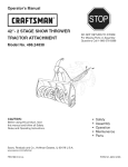
Operator's IVlanuai
CRRFr. MgN°
42"- 2 STAGE SNOW THROWER
DO NOT RETURN
TRACTOR ATTACHMENT
TO STORE
For Missing Parts or Assembly
Questions Call 1-866-576-8388
IVlodei No. 486.24837
FOR TRACTORS
WiTH MODEL NUMBERS
CAUTION:
and Co., Hoffman
WiTH 917.
,,
,,
,,
,,
,,
Before using this product, read
this manual and follow all Safety
Rules and Operating Instructions.
Sears, Roebuck
BEGiNNiNG
Safety
Assembly
Operation
Maintenance
Parts
Estates, IL 60179 U.S.A.
www.sears.com/craftsman
PRINTED IN U.S.A.
FORM NO. 41361 rev. (07/30/10)
ACCESSORIES ...............................................................
2
SAFETY RULES ..............................................................
3
FULL SIZE HARDWARE CHART .................................... 4
CARTON CONTENTS .....................................................
6
ASSEMBLY ......................................................................
7
OPERATION ..................................................................
26
MAINTENANCE ............................................................
27
SERVICE AND ADJUSTMENTS ................................... 28
STORAGE .....................................................................
29
TROUBLESHOOTING ...................................................
29
REPAIR PARTS ILLUSTRATION ........................ 30,32,34
REPAIR PARTS LIST ........................................... 31,33,34
SLOPE GUIDE ..............................................................
35
PARTS ORDERING/SERVICE ................... BACK COVER
ONE YEAR FULL WARRANTY
When operated and maintained according to the instructions supplied with it, if this Snow Thrower fails due to a defect in
material or workmanship within one year from the date of _urchase, call 1-800-4-MY-HOME@ to arrange for free repair (or
replacement if repair proves impossible).
If this product is used for commercial or rental purposes, this warranty applies for only 90 days from the date of purchase.
This warranty gives you specific legal rights, and you may also have other rights which vary from state to state.
Sears, Roebuck and Co., D817WA, Hoffman Estates, IL 60179
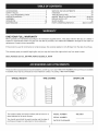
These and other accessories are recommended for use with your unit. Call 1-800-4-MY-HOME® to find out if they are available.
If available, they may be purchased at most Craftsman outlets or by calling 1-800-4-MY-HOME®.
WHEEL WEIGHT
TiRE CHAINS
The model number and serial numbers will be found on a
decal attached to the snow thrower.
You should record both the serial number and the date of
purchase and keep in a safe place for future reference.
MODEL NUMBER:
SERIAL NUMBER:
DATE OF PURCHASE:
SNOW CAB
486.24837
Anypowerequipment
cancauseinjuryifoperated
improperly
oriftheuserdoesnotunderstand
howtooperatetheequipment.
Exercisecautionatalltimes,whenusingpowerequipment.
• Readthisowner'smanualcarefullyandknowhowto
operateyoursnowthrowerandhowto stoptheunit
anddisengage
thecontrolsquickly.
Neverallowchildrentooperatetheequipment.
Neverallowadultsto operatetheequipment
without
properinstruction.
Keeptheareaofoperation
clearofallpersons,
especially
smallchildren,andpets.
Thoroughly
inspecttheareawheretheequipment
is
tobeusedandremovealldoormats,sleds,boards,
wiresandotherforeignobjects.
Disengage
allclutchesandshiftintoneutralbefore
startingengine.
Donotoperateequipment
withoutwearingadequate
winteroutergarments.
Wearsubstantial
footwearwhichwillprotectfeetand
improvefootingonslipperysurfaces.
Checkfuelbeforestartingtheengine.Donotremove
thefuelcapor fillthefueltankwhiletheengine
is runningor hot.Donotfillthefueltankindoors.
Gasolineis anextremely
flammable
fuel.
Makesurethesnowthrowerheightis adjustedto
clearthetypesurfaceitwillbeusedon.
Donotusethesnowthrowerwithoutwheelweights
attachedtothetractor.
Nevermakeanyadjustments
whiletheengineis
running.
Alwayswearsafetyglassesor eyeshieldduring
operation
or whileperforming
adjustment
orrepair.
Donotplacehandsorfeetnearrotatingparts.Keep
clearofthedischarge
openingatalltimes.
Useextremecautionwhenoperating
onorcrossing
gravelsurfaces.
Donotcarrypassengers.
Afterstrikinga foreignobject,stoptheengine,remove
thewirefromthesparkplugandthenthoroughly
inspectthesnowthrowerfordamage.Repairany
damagebeforerestarting
andoperating
thesnow
thrower.
If thesnowthrowerstartstovibrateabnormally,
stop
theengineimmediately
andcheckforthecause.
Vibrationis generallya warningoftrouble.
Stoptheenginewhenever
youleavetheoperating
position,beforeunclogging
thesnowthroweror
makinganyadjustments
or inspections.
Takeallpossibleprecautions
whenleavingtheunit
unattended.
Disengage
theattachment
clutchleveror
switch,lowerthesnowthrower,shiftintoneutral,set
theparkingbrake,stoptheengineandremovethe
key'.
Whencleaning,repairingor inspecting,
makecertain
allmovingpartshavestopped.Disconnect
thespark
plugwireandkeepitawayfromtheplugtoprevent
accidental
starting.
Donotrunengineindoorsexceptwhentransporting
thesnowthrowerinor outofthebuilding.Openthe
outsidedoors.Exhaustfumesaredangerous.
Donotclearsnowacrossthefaceofslopes.Exercise
extremecautionwhenchangingdirectiononslopes.
Donotattempttoclearsteepslopes.Refertothe
slopeguideonpage35ofthismanual.
Neveroperatethesnowthrowerwithoutguards,
platesorothersafetyprotectiondevicesin place.
Neveroperatethesnowthrowernearglass
enclosures,
automobiles,
windowwells,dropoffs
etc.withoutproperadjustment
ofthesnowthrower
discharge
angle.
Neverdirectdischarge
atbystanders
or allowanyone
infrontofthesnowthrower.
Neverrunthesnowthrowerintomaterialathigh
speeds.
Donotoverloadthemachinecapacitybyattempting
toclearsnowattoofasta rate.
Neveroperatethemachineathightransportspeed
onslipperysurfaces.
Lookbehindandusecarewhen
backingup.
Watchfortrafficandstayalertwhencrossingor
operatingnearroadways.
Disengage
powertothesnowthrowerwhen
transporting
orwhennotin use.
Useonlyattachments
andaccessories
approved
by
themanufacturer
ofthesnowthrower(suchaswheel
weights,counterweights,cabsetc.)
Neveroperatethesnowthrowerwithoutgoodvisibility
or light.
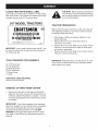
Lookforthissymboltopointoutimportant
safetyprecautions.
Itmeans--Attention!!Become
alert!!Your safety is involved.
SHOWN ACTUAL
SIZE
r--qq
fA
jB
C
J
H
zD
jG
/E
_jF
.......
m
43182
43063
43661
43840
43351
43020
43084
• JL
49933
48106
46938
_
, _
43350
_
_
4_
43O80
43682
710-0890A
44215
V
. W,X
T
R19171616
43088
47630
49948
_ ............
47605, 43070
43081
47631
_\\\\\\
\
AA
/Z
jCC
_Y
43086
/
24817
43003
44695
R19172410
DD
EE
712-3083
43019
GG
jFF
/
HA21362
HH
ill
/
43082
47810
4
47572
zJJ
46584
jKK
47598
NOT SHOWN
LL
ACTUAL
MM
46959
731-0851A
NN
PP
OO
711-0198
QQ
SiZE
43343
47134
RR
[__z
43055
SS
714-04061
43038
TT
1643-60
_
UU
23727
VV
z XX
j WW
726-0178
47788
46963
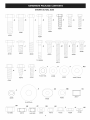
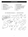
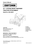
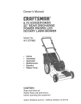
IMPORTANT:
Not all items supplied in the hardware bag will be needed for your particular tractor. Unneeded items may
be discarded after you have completed assembly and checked operation of unit. DO NOT DISCARD the two spare shear
bolts (K) and 5/16" nylock nuts (HH). Refer to the Service and Adjustments section on page 28.
REF.
A
B
QTY.
2
2
C
D
E
1
2
2
F
G
H
I
J
K
L
M
N
O
P
Q
R
S
T
U
V
W
X
Y
Z
4
8
6
4
2
2
6
2
2
4
2
6
2
2
4
7
22
1
3
2
8
DESCRIPTION
Hex Bolt, 1/2" x 1-1/2"
Hex Bolt, 1/2" x 1-1/4"
Hex Bolt, 3/8" x 3-1/4"
Hex Bolt, 5/16" x 1-3/4"
Hex Bolt, 5/16" x 1-1/4"
Hex Bolt, 5/16"x 1"
Hex Bolt, 5/16" x 3/4"
Hex Bolt, 1/4" x 1"
Shoulder Bolt, Hex Head
Shoulder Bolt, Round Head
Shear Bolt (spare parts)
Carriage Bolt, 3/8" x 1"
Carriage Bolt, 5/16"x 1-3/4"
Carriage Bolt, 5/16" x 1-1/4"
Carriage Bolt, 5/16"x 1"
Carriage Bolt, 5/16" x 3/4"
Hex Bolt, 3/8" x 1" (Thread Forming)
Hex Bolt, 3/8" x 3/4" (Thread Forming)
Hex Bolt, 5/16" x 3/4" (Thread Forming)
Washer, 1/2" x 1"
Washer, 1/4"
Washer, 5/16" (Extra washers included)
Washer, 3/8" (Thin)
Washer, 3/8" Standard
Lock Washer, 5/16"
Washer, 1/2" x 1-1/2"
REF.
AA
BB
QTY.
2
7
CC
DD
EE
2
4
4
FF
GG
HH
II
JJ
KK
LL
MM
NN
OO
PP
QQ
RR
SS
TT
UU
VV
WW
XX
6
2
21
10
1
6
1
3
1
4
4
1
2
2
1
1
2
2
2
DESCRIPTION
Bowed Washer
Lock Washer, 3/8"
Spacer, 1/2"
Nylock Nut, 1/2"
Jam Nut, 1/2"
Nylock Nut, 3/8"
Hex Lock Nut, 3/8"
Nylock Nut, 5/16" (2 spare parts)
Flanged Nut, 3/8"
Flanged Nut, 5/16"
Flanged Nut, 1/4"
Spring
Chute Keeper
Trunnion
Hairpin Cotter, 5/64"
Hairpin Cotter, 1/8"
Hairpin Cotter, 3/32"
Lock Pin
Quick Release Pin
Plastic Cap
Spacer, 3/8"
Chain, Tensioning
Tail Reflector
Nylon Tie
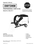
1.
2.
3.
4.
5.
6.
7.
8.
9.
10.
11.
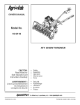
HousingAssembly
LiftHandleandCable
ChuteCrankRodAssembly
SupportTube,CrankRod
Engagement
Rod(Notusedonsomemodels)
CableBracket
EnginePulleyKeeper(Notusedonsomemodels)
ChuteandControlCableAssembly
ClutchIdlerAssembly
RearPulleyFrameBracket(2)
Anti-rotation
Bracket.
ONLY ITEMS NEEDED
12.
13.
14.
15.
16.
17.
18.
19.
20.
21.
22.
23.
FrontPulleyFrameBracket(2)
V-Belt,Drive56"(#48138)
V-Belt,Drive55"(#46989)
V-Belt,Auger(Attached
to HousingAssembly)
L.H.HangerBracket(OutsideMounting)
R.H.HangerBracket(OutsideMounting)
L.H.HangerBracket(InsideMounting)
R.H.HangerBracket(InsideMounting)
LeftHandSidePlate
RightHandSidePlate
Pulley
Spacer,3/8"
FOR MODEL 917.
TRACTORS
_1
ARE SHOWN
3
lO
/5
11
24558
47043
j9
13
24394
25728
_
_5
12
/8
270 ] 6
48138_J
16
65367
17
64451
65450
19
18
22
64452
20
21
23
8
48883
25780
25678
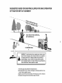
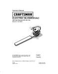
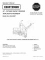
LOCATE TRACTOR'S
MODEL
LABEL
CAUTION:
Before starting to assemble the
snow thrower, remove the spark plug wire(s),
set the parking brake and remove the key
from the tractor ignition.
Look under your tractor seat to locate the model number
label shown below. This manual if for tractors with model
numbers that start with 917 as shown below.
917 MODEL TRACTORS
TRACTOR
CRRFTXllIRH+
CONFORMS
TO
ANSi
B71,1=2003
SAFETY
Before performing these instructions, refer to the Service
and Adjustments section of your tractor owner's manual
for specific safety instructions.
STANDARDS
III |1 111111|1|
IIIIIIIl lllllllllll
SERIAL
FOR PARTS
SEARS,
•
000000A000000
AND SERVICE
ROEBUCK
AND
CAll
CO,
•
1-BOO-4MY-HQME
Iloffman
Estates,
I[ 60179
193653
j
•
IMPORTANT: If your model number starts with 247, use
the owner's manual and the parts that are contained in
the other parts bag.
TOOLS
(2)
(2)
(2)
(2)
(1)
(1)
REQUIRED
FOR ASSEMBLY
7/16" Wrenches
1/2" Wrenches
9/16" Wrenches
3/4" Wrenches
Screw Driver
Knife
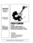
ADDITIONAL ITEMS REQUIRED
General Purpose Grease
REMOVAL
PREPARATION
OF PARTS FROM CARTON
Remove all loose parts, parts bags and hardware
bags from the carton. Lay out and identify parts and
hardware using the illustrations on pages 4, 5 and 6.
The parts bag labeled for 247 model tractors will not
be needed.
IMPORTANT:
Not all items supplied in the hardware
bag will be needed for your particular tractor. Unneeded
items may be discarded after you have completed
assembly and checked operation of unit. DO NOT
DISCARD the two spare shear bolts and 5/16" nylock
nuts. Refer to the Service and Adjustments section on
page 28.
•
Allow engine, muffler and exhaust deflector to cool
before beginning.
Remove any front or rear attachment which is
mounted to your tractor.
Remove the mower deck. Refer to your tractor owner's
manual for removal instructions. Mark all loose parts
and save for reassembly.
Remove the tractor hood. Refer to your tractor owner's
manual for removal instructions.
IMPORTANT: Right hand (R.H.) and left hand (L.H.) side
of the tractor are determined from the operators position
while seated on the tractor.
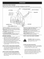
IDENTIFYYOUR
TRACTOR
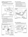
iNSTALL
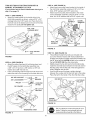
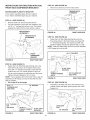
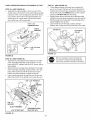
STEP 1: (SEE FIGURE 1)
o Look under the front of your tractor. If there is a single
mower deck suspension bracket located underneath
the middle of the front axle, continue on to step
2. if your tractor does not have a mower deck
suspension bracket underneath the middle of the
front axle, skip to step 21 on page 14 for tractors
with dual suspension brackets.
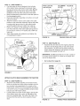
SIDE PLATES
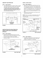
STEP 3: (SEE FIGURE 3)
Fasten the R.H. Side Plate (bend facing out) to the
front three holes in the tractor frame using three 3/8"
x 1" carriage bolts, three 1/2" x 1-1/2" washers (see
note) and three 3/8" flange nuts. For the rear hole, use
a 5/16" x 1" carriage bolt, a 1/2" x 1-1/2" washer and
a 5/16" nylock nut Place the washers between the
tractor frame and the side plate. Repeat for L.H. side
plate.
•
Reinstall the browning shield onto the tractor frame
using the original screws.
NOTE: If there is an engine mounting plate (shown with
dotted lines) leave the washer off the bolt that goes
through the plate.
5/16" x 1"
CARRIAGE
ENGINE MOUNTING
PLATE
BOLT
SEE NOTE
5/16"
NYLOCK
NUT
FIGURE 1
(3) 3/8" x 1"
CARRIAGE
BOLTS
iNSTRUCTiONS
FOR TRACTORS WITH
SINGLE FRONT DECK SUSPENSION
BRACKET
(4) 1/2" x 1-1/2"
(3) 3/8" FLANGE
FIGURE
STEP 2: (SEE FIGURE 2)
Remove the browning shield from the front of the
tractor as shown. Hold onto the shield as you remove
the second screw to prevent it from falling.
Be sure to reinstall the browning shield when so
instructed in step 3.
WASHERS
NUTS
RIGHT SIDE VIEW
3
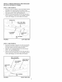
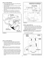
STEP 4: (SEE FIGURE 4)
Assemble a shoulder bolt and a 3/8" washer to the
outside of R.H. side plate, securing it with a 3/8"
flanged nut. Repeat for L.H. side plate.
REMOVE
FRONT SCREWS
REMOVE
BROWNING SHIELD
BOLT
3/8" WASHER
FIGURE 2
3/8" FLANGED
NUT
RIGHT SIDE VIEW
FIGURE 4
RIGHT SIDE VIEW
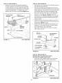
iNSTALL HANGER BRACKETS
AND SHOULDER
BOLTSTO
OUTSIDE OF FRAME
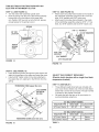
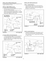
STEP 5: (SEE FIGURE 5)
,
*
*
Remove the bolt, if present, in the hole directly behind
the brake rod on the left side of the tractor frame.
Attach the L.H. Hanger Bracket (tube facing out) to the
hole using a 5/16" × 3/4" self threading bolt.
Install a round head shoulder bolt into the hole that is
9-1/2" to the rear of the bolt you just installed. Secure
it with a 3/8" flange nut on the inside of the frame.
BRAKE ROD
5/16" x 3/4" SELF
THREADING BOLT
L.H. HANGER
BRACKET
,
\
\\
\
\
\
\
\
3/8" FLANGED
NUT
\_
FIGURE 5
LEFT SIDE ViEW
STEP 6: (SEE FIGURE 6)
o
Remove the bracket, if present, from the hole directly
behind the end of the brake rod on the right side of
the tractor frame. Store the bracket and bolt.
Attach the R.H. Hanger Bracket to the hole using a
5/16" x 3/4" self threading bolt.
Install a round head shoulder bolt into the hole that is
9-1/2" to the rear of the bolt you just installed. Secure
it with a 3/8" flange nut on the inside of the frame.
5/16"x3/4"SELF
THREADING
BOLT
RIGHTENDOF
BRAKEROD
R.H. HANGER
BRACKET
SHOULDER
BOLT
3/8" FLANGED
NUT
FIGURE 6
RIGHT SiDE ViEW
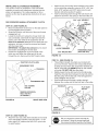
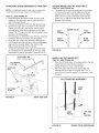
THIS SECTION IS FOR TRACTORS
MAN UAL ATTACHM ENT CLUTCH
WITH A
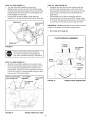
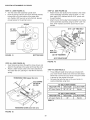
STEP 9: (SEE FIGURE 9)
Attach each rear pulley frame bracket to the inside of
the clutch/idler assembly using two 5/16" x 3/4" hex
bolts, 5/16" washers and 5/16" nylock nuts.
Attach each front pulley frame bracket to the inside
of the clutch/idler assembly using two 5/16" x 1" hex
bolts, four 5/16" washers and two 5/16" nylock nuts.
if your tractor has an electric attachment clutch go to
step 14 on page 12.
STEP 7: (SEE FIGURE 7)
o Attach the cable bracket to the double hole in the
clutch/idler assembly as shown, using a 5/16" x 3/4"
carriage bolt and a 5/16" nylock nut. Place the bolt in
the front hole of the bracket and in the end of the hole
closest to the pulley. Do not tighten
5/16"
5/16" x 1"
HEX BOLT
yet.
(2) 5/16"
WASHERS
/
x 3/4"
CARRIAGE
BOLT
CABLE
BRACKET
5/16" x 3/4"
HEX BOLT
_
_
5/16" WASHER
5/16"
NYLOCK
NUT
FIGURE 9
{
_
5116" NYLOCK
NUT
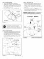
STEP 10: (SEE FIGURE 10)
• Three different length drive belts are included with
your snow thrower. Tractors with manual attachment
clutches and single front deck suspension brackets use
the 56" drive belt with #48138 printed on the outside of
the belt. DO NOT USE the other drive belts.
• Slightly loosen the hex bolt next to the fiat idler pulley.
install the drive belt down between the hex bolt and the
fiat idler pulley with the fiat side of the belt against the
pulley. Retighten the hex bolt.
• Loop the belt around the large v-pulley, placing it
between the v-pulley and the hex bolt next to the pulley.
Place the belt to the inside of the other fiat idler pulley.
FIGURE 7
STEP 8: (SEE FIGURE 8)
Attach the pulley (long end of hub facing down) and
the 3/8" spacer to the clutch/idler assembly. Use
a 3/8" x 3-1/4" hex bolt, a 3/8" washer, a 3/8" lock
washer and a 3/8" hex lock nut.
insert a tensioning chain through the hole shown and
attach the end link to the spring on the lower idler arm.
HEX BOLTS
iDLER
PULLEYS
(#46136) 7
DRIVE BELT
FIGURE 10
TENSiONiNG
Did you select the correct drive belt for your
tractor? Using the wrong length belt may
cause premature bearing or belt failure.
CHAIN
FIGURE 8
10
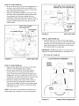
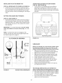
STEP11: (SEEFIGURE11)
*
*
*
*
*
*
PIVOT LOCK PiN
(use this hole)
Find the cable clip that is attached to the left side
of the tractor frame underneath the footrest. Open
the clip and remove the mower clutch cable. Do not
remove the clip from the tractor frame. The cable
reattaches to the clip when using the mower deck.
Move the attachment clutch lever on the dash panel to
the disengaged position.
Place the clutch/idler assembly on the floor on the left
side of the tractor.
Attach the tractor's mower clutch cable to the cable
bracket on the clutch/idler assembly. Secure the cable
housing guide (groove down) to the cable bracket
using the original collar and a 5/64" hair cotter pin.
Place a 1/4" spacer on the welded pin on the idler
arm. Hook the end of the clutch cable spring over the
pin and secure it with a 1/4" washer and a 5/64" hair
cotter pin.
Align cable bracket with welded pin and tighten the
nut assembled in step 9.
1/8" HAiRPiN
COTTER
L.H. HANGER
FIGURE 12
NYLON TiE
SHOULDER
BOLT
J
VIEWED FROM LEFT SiDE
STEP 13: (SEE FIGURE 13)
Assemble the drive belt onto the engine pulley first
and then onto the large pulley on top of the clutch/
idler assembly. The belt must be placed inside the
engine pulley belt keeper(s) and between the large
pulley and the keeper bolt next to it.
iMPORTANT:
1/4" SPACER
Do Not assemble the "V" belt outside of
the engine pulley keepers or outside of the keeper bolt
next to the large pulley.
5/64" HAiR
COTTER PiN
*
TRACTOR'S
CLUTCH CABLE
Go to step 48 on page 22.
ENGINE
PULLEY
KEEPER
CABLE
BRACKET
\
FIGURE 11
ATTACH CLUTCH
ENGINE
PULLEY
KEEPER
/
iDLER ASSEMBLY TO TRACTOR
Left Side
of Tractor
STEP 12: (SEE FIGURE 12)
• Attach the clutch/idler assembly to the tractor frame.
Hook the notched rear pulley frame brackets onto the
two shoulder bolts assembled to the outside of the
tractor frame. Lift the front of the assembly and attach
it to the R.H. and L.H. hanger brackets using two pivot
lock pins and 1/8" hairpin cotters.
Loosely attach the mower clutch cable to the left side
of the tractor frame with a nylon tie. Do not pull the
nylon tie completely tight. The cable may need to be
removed from the nylon tie when using the mower
deck.
PULLEY
FIGURE 13
11
KE!PEI
BOLT
VIEWED FROM UNDERNEATH
THIS SECTION IS FOR TRACTORS
ELECTRIC ATTACHMENT
CLUTCH
WITH AN
STEP 14: (SEE FIGURE 14)
• Turn the clutch idler assembly upside down.
• Hook the spring onto the end of the bolt that extends
through the nut on the bottom of the upper idler
arm. Install a 3/8" hex lock nut onto the bolt, leaving
enough space for the spring to pivot.
STEP 18: (SEE FIGURE 16)
Attach each rear pulley frame bracket to the inside of
the clutch/idler assembly using two 5/16" x 3/4" hex
bolts, 5/16" washers and 5/16" nylock nuts.
Attach each front pulley frame bracket to the inside
of the clutch/idler assembly using two 5/16" x 1" hex
bolts, four 5/16" washers and two 5/16" nylock nuts.
SPRING
3/8" HEX
5116" x 1" HEX BOLT
F'
LOCK NUT
(2) 5116" WASHERS
©
ATTACH
SPRING
HERE
/
5116"
NYLOCK NUT
5116" x 314"
HEX BOLT
"_
5/16" WASHER
/
5/16" NYLOCK NUT
FIGURE 14
FIGURE 16
STEP15: (SEE FIGURE 15)
Insert tensioning chains through the holes shown and
attach to the springs on the upper and lower idler arms.
Install a 3/32" hairpin cotter in the chain attached to
the upper idler arm, placing it in the fifth link from the
spring.
TENSIONING
SELECTTHE
CORRECT
(Electric clutch tractors
suspension
bracket)
STEP 17: (SEETABLE
CHAIN (upper idler arm)
3132" HAIRPIN
//COTTER
IN
5th LINK
•
DRIVE
BELT
with a single
front
deck
1)
Three different length drive belts are included with
your snow thrower. Select one of the two belts listed
below that is correct for your tractor. The part number
is printed on the outside of the belt.
Set aside the belts that are not for your tractor, to
avoid accidentally using them.
55" BELT (PART #46989)
TRACTOR TYPE
DECK SIZE
CLUTCH TYPE
(LT) Lawn Tractor
38", 42"
Electric
56" BELT (PART #48138)
TRACTOR TYPE
DECK SIZE
CLUTCH TYPE
TENSIONING
FIGURE
CHAIN (lower idler arm)
(LT) Lawn Tractor
48"
Electric
(GT) Garden Tractor
48", 54"
Electric
TABLE 1
15
12
STEP 18: (SEE FIGURE 17)
e
Turn the clutch/idler assembly right side up.
e
Slightly loosen the hex bolt next to the flat idler pulley.
Install the drive belt down between the hex bolt and the
flat idler pulley with the flat side of the belt against the
pulley. Retighten the hex bolt.
Loop the belt around the large v-pulley, placing it
between the v-pulley and the hex bolt next to the pulley.
HEX BOLTS
STEP 20: (SEE FIGURE 19)
• Assemble the drive belt onto the engine pulley first
and then onto the large pulley on top of the clutch/
idler assembly. Place the belt to the inside of the idler
pulley and the belt keeper bolt located beside the
large pulley.
Place tension on the belt by pulling the left side
tensioning chain out as far as the 3/32" hairpin cotter
in the chain will allow. Secure the chain in this position
by inserting a 1/8" hairpin cotter through the chain.
FLAT iDLER
PULLEY
IMPORTANT: Do Not assemble the drive belt around the
outside of the keeper bolt beside the large pulley.
Go to step 48 on page 22.
CLUTCH/IDLER
ASSEMBLY
DRIVE BELT
FIGURE
17
1/8" HAiRPiN
COTTER
/
Did you choose the correct drive belt for
your tractor? Using the wrong length belt
may cause premature bearing or belt failure.
iDLER
STEP 19: (SEE FIGURE 18)
Attach the clutch/idler assembly to the tractor frame.
Hook the notched rear pulley frame brackets onto the
two shoulder bolts assembled to the outside of the
tractor frame. Lift the front of the assembly and attach
it to the R.H. and L.H. hanger brackets using two pivot
lock pins and 1/8" hairpin cotters.
CHAIN
(L.H. SIDE)
KEEPER
BOLT
)
PIVOT LOCK PiN (MM)
(use second hole)
FIGURE 18
LH. HANGER
BRACKET
SHOULDER I
BOLT
FIGURE 19
VIEWED FROM LEFT SIDE
13
VIEWED FROM UNDERNEATH
iNSTRUCTiONS
FOR TRACTORS WITH DUAL
FRONT DECK SUSPENSION BRACKETS
FASTEN
SIDE PLATES
STEP 23: (SEE FIGURE 22)
*
Remove any bolts found in the holes shown.
REMOVE BOLTS
IF PRESENT
TO TRACTOR
if your tractor resembles figure 20, go to step 21.
If your tractor resembles figure 22, go to step 23.
STEP 21: (SEE FIGURE 20)
*
Remove bolts from front three holes shown.
*
If a bolt is present in the fourth hole, replace it with
a 5/16" x 1" carriage bolt without a nut. The bracket
fastened to inside of frame must remain in place.
SUSPENSION
BRACKET
REPLACE BOLT
(IF PRESENT)
FIGURE 22
REMOVE BOLTS
(IF PRESENT)
RIGHT SiDE ViEW
STEP 24: (SEE FIGURE 23)
*
Fasten the R.H. Side Plate (bend facing out) to the
three holes shown in the tractor frame. Use three 3/8"
x 1" thread forming bolts, 1/2" washers and 3/8" lock
washers. Tighten all bolts and repeat for the L.H. side.
NOTE: If the bolt inserts freely into the front hole, assemble
a 3/8" flanged nut onto the bolt.
(3) 1/2"WASHERS
FRONT
SUSPENSION
BRACKET
FIGURE 20
RIGHT SiDE ViEW
STEP 22: (SEE FIGURE 21)
*
Fasten the R.H. Side Plate (bend facing out) to the
front three holes shown in the tractor frame using
three 3/8" x 1" thread forming bolts, three 3/8" lock
washers and one 1/2" washer placed on the third
bolt as a shim between the side plate and the frame.
Tighten all bolts. Repeat for the L.H. side.
NOTE: If you installed a bolt in the fourth hole in step 21,
assemble a 5/16" flange nut onto the bolt after the side
plate is installed.
*
Go to step 25 on this page.
5/16" x 1"
CARRIAGE
(3) 3/8"LOCK
WASHERS
(3) 3/8" x 1"
THREAD FORMING
BOLTS
FIGURE
RIGHT SiDE ViEW
23
1/2"WASHER
outside of each side plate, securing them with a 3/8"
flanged nut.
BOLT
FLANGED
SHOULDER
BOLT
NUT
(SEE
NUT
(SEE NOTE)
STEP 25: (SEE FIGURE 24)
*
Assemble a shoulder bolt and a 3/8" washer to the
(SEE NOTE)
5/16"
318" FLANGED
NOTE)
(3) 3/8" x 1"
THREAD
FORMING
BOLTS
FIGURE 21
(3) 3/8" LOCK
WASHERS
3/8" WASHER
RIGHT SiDE ViEW
FIGURE 24
14
3/8" FLANGED
NUT
RIGHT SiDE ViEW
INSTALLING
iNSTALLiNG
HANGER BRACKETS
For better clearance, lower the tractor's suspension arms
using the attachment lift lever.
*
BOLTS
STEP 27: (SEE FIGURE 27)
Remove the bolt, washer and nut which fasten the
sway bar bracket to the L.H. side of the tractor frame.
Replace with a shoulder bolt and a 3/8" flanged nut.
Bolt goes on inside of frame.
STEP 26: (SEE FIGURE 25 or 26)
On Tractors With Foot Rest Brackets
*
SHOULDER
Remove the bolt and nut that fasten the L.H. and R.H.
foot rest brackets to the frame.
Attach the L.H. Hanger Bracket (marked "L") to the
inside of the tractor frame using two 3/8" x 1" carriage
bolts and 3/8" flanged nuts. Bolt heads go on inside of
tractor frame. Repeat for the R.H. side.
@
BOLT
REMC,VED
FROM THIS HOLE
3/8" FLANGED
NUT
SHOULDER BOLT
BOLT REMOVED
FROMTHiS HOLE
_\'\
SWAY BAR
\\
\'\. BRACKET
FIGURE 27
!
3/8" x 1"
CARRIAGE
BOLT
*
Y
/ NUT
LEFT SIDE VIEW
SUSPENSION ARM
\
\
L.H. HANGER
BRACKET
_.
--
FIGURE 25
On Tractors Without
3/8"
FLANGED
STEP 28: (SEE FIGURE 28)
Assemble a shoulder bolt and 3/8" flanged nut to the
R.H. side of the tractor frame, using the first empty
hole to the rear of the R.H. hanger bracket. Bolt goes
on inside of frame.
LEFT SIDE VIEW
Foot Rest Brackets
Find the empty hole beneath the foot rest. Attach the
L.H. Hanger Bracket (marked "L") to the inside of
the frame using a 3/8" x 1" carriage bolt and a 3/8"
flanged nut. Bolt head goes on inside of tractor frame.
Repeat for the R.H. side.
3/8" FLANGED
SHOULDER
BOLT
R.H. HANGER BRACKET
SUSPENSION
ARM
\
\
L.H. HANGER
BRACKET
FIGURE
26
FIGURE 28
\\\
_.
LEFT SIDE VIEW
15
RIGHT SIDE VIEW
iNSTALLiNG
CLUTCH/IDLER
ASSEMBLY
This section covers the installation of the Clutch/Idler
Attach the two front pulley frame brackets to the inside
of the clutch/idler assembly using two 5/16" x 3/4" hex
bolts, 5/16" washers and 5/16" nylock nuts for each
bracket. Add extra washers if needed.
Insert a tensioning chain through the hole shown and
attach the end link to the spring on the lower idler arm.
assembly to tractors with attachment clutches that are
either rod operated (p. 16), cable operated (p. 18) or
electric (p. 20). Use the appropriate instructions for your
tractor.
5116"x 3/4" HEX BOLT
ROD OPERATED MANUAL ATTACHMENT CLUTCH
5/16"
WASHER
/
STEP 29: (SEE FIGURE 29)
• Move the attachment clutch lever on the dash panel to
the disengaged (down) position.
Screw the trunnion onto the end of the snow thrower
engagement rod.
Locate the clutch arm (where the mower clutch rod
was connected) underneath the right hand side the
tractor, just to the inside of the suspension arm. If
there is an extension attached to the clutch lever, the
extension, bolt and nut must be removed and stored
with the mower deck.
IMPORTANT: Re=attach the extension to the clutch
5/16" x 1"
HEX BOLT
(4) 5/16" WASHERS
lever before reinstalling the mower deck.
Position the engagement rod to the inside of the
clutch arm and insert the drilled end of the rod
through the arm. Secure with a 5/64" hairpin cotter.
TRACTOR'S
5/16" NYLOCK NUT
FIGURE
/
/
TENSIONING CHAIN
(lower idler arm)
30
STEP 31: (SEE FIGURE 31)
Three different length drive belts are included with
your snow thrower. Tractors with manual attachment
clutches and dual front deck suspension brackets use
the 55" drive belt with #46989 printed on the outside
of the belt. DO NOT USE the other belts.
Slightly loosen the hex bolt next to the flat idler pulley.
Install the drive belt down between the hex bolt and the
flat idler pulley with the flat side of the belt against the
pulley. Retighten the hex bolt.
Loop the belt around the large v-pulley, placing it
between the v-pulley and the hex bolt next to the pulley.
CLUTCH ARM
ENGAGEMENT ROD
/
\
SUSPENSION ARM
5/64" HAIRPIN
COTTER
HEX BOLTS
FLAT IDLER
PULLEY
REMOVE EXTENSION,
BOLT AND NUT
(IF PRESENT)
FIGURE
29
RIGHT SIDE VIEW
#46989
DRIVE
FIGURE
STEP 30: (SEE FIGURE 30)
Attach the two rear pulley frame brackets to the inside
of the clutch/idler assembly using two 5/16" x 1" hex
bolts, eight 5/16" washers and two 5/16" nylock nuts
for each bracket.
,/_
BELT
31
Did you choose the correct drive belt for
your tractor? Using the wrong length belt
may cause premature bearing or belt failure.
16
STEP32: (SEEFIGURE32)
• Besuretoliftupthefrontendoftheengagement
rod
asshownwhenperforming
thenextoperation.
You
cantemporarily
supporttherodusinga rubberband
tiedtotheenginepulleykeeper.
Attachtheclutch/idler
assemblytothetractorframe
asfollows.Hooktheassembly's
notchedrearpulley
framebracketsontothetwoshoulderboltsyou
assembled
to theinsideofthetractorframe.Liftthe
frontoftheassemblyandattachittothe R.H.andL.H.
hangerbracketsusingtwopivotlockpinsand1/8"
hairpincotters.
PIVOT
__
.......
LOCK
HAiRPiN
TRUNNION
[]
J
STOP BOLT
iDLER ARM
3/8" THiN
PIN (MM)
WASHER
5/64" HAiRPiN
COTTER
(use second hole)
.............................
1/8"
NEW ENGINE PULLEY KEEPER WiTH
ORiGiNAL BOLT, NUT AND WASHER
ENGAGEMENT
COTTER
FIGURE
RIGHT SiDE VIEW
33
STEP 34: (SEE FIGURE 34)
Assemble the short "V" belt onto the engine pulley
and then onto the large pulley on top of the clutch/idler
assembly. The belt must be placed to the inside of the
engine pulley keeper, the idler pulley and the keeper
bolt located beside the large pulley.
f
iMPORTANT:
Do Not assemble the "V" belt around the
outside of the engine pulley keeper or the keeper bolt.
Go to step 48 on page 22.
FIGURE 32
CLUTCH/IDLER
RIGHT SiDE VIEW
ENGINE
PULLEY
KEEPER
STEP 33: (SEE FIGURE 33)
Make sure the attachment clutch lever on the dash
panel is in the disengaged (down) position.
Pivot the upper idler arm so that it rests against
the stop bolt and is pointing toward the front as
shown. Screw the trunnion along the threads of the
engagement rod until it is aligned at the front end of
the idler arm slot. Attach the trunnion to the slot using
the 3/8" thin washer and a 5/64" hairpin cotter.
Remove the engine pulley keeper from the side of
the tractor frame by removing the washer and nut
that secure the keeper. Attach the new pulley keeper
supplied with the snow thrower, reusing the original
bolt, washer and nut.
ASSEMBLY
Left Side
of Tractor
ENGINE
PULLEY
NOTE: Some tractors may already be equipped with a
pulley keeper that is identical to the new one supplied.
BOLT
FIGURE 34
17
VIEWED FROM UNDERNEATH
CABLEOPERATED
MANUAL
ATTACHMENT CLUTCH
STEP 37: (SEE FIGURE 37)
Three different length drive belts are included with
your snow thrower. Tractors with manual attachment
clutches and dual front deck suspension brackets use
the 55" drive belt with #46989 printed on the outside
of the belt. DO NOT USE the other belts.
Slightly loosen the hex bolt next to the fiat idler pulley.
Install the drive belt down between the hex bolt and the
fiat idler pulley with the fiat side of the belt against the
pulley. Retighten the hex bolt.
Loop the belt around the large v-pulley, placing it
between the v-pulley and the hex bolt next to the pulley.
STEP 35: (SEE FIGURE 35)
* Assemble the cable bracket to the inner half of the
double holes in the bottom of the clutch/idler assembly
using two 5/16" × 3/4" carriage bolts and 5/16" nylock
nuts. Use the front holes in the cable bracket if your
tractor has a 42" mower deck. Use the rear holes if
your tractor has a 46" mower deck.
5/16" x 3/4"
CARRIAGE BOLT
CABLE
BRACKET
46"
DECKS
42"
DECKS
_@ _
HEX BOLTS
5/16" NYLOCK
NUT
#46989
DRIVE
FLAT iDLER
PULLEY
,_
BELT
FIGURE 37
FIGURE
35
Did you choose the correct drive belt for
your tractor? Using the wrong length belt
may cause premature bearing or belt failure.
STEP 36: (SEE FIGURE 36)
• Attach the two rear pulley frame brackets to the inside
of the clutch/idler assembly using two 5/16" x 1" hex
bolts, eight 5/16" washers and two 5/16" nylock nuts for
each bracket.
Attach the two front pulley frame brackets to the inside
of the clutch/idler assembly using two 5/16" x 3/4" hex
bolts, 5/16" washers and 5/16" nylock nuts for each
bracket. Add extra washers if needed in step 39.
Insert a tensioning chain through the hole shown and
attach the end link to the spring on the lower idler arm.
5/16" x 3/4" HEX BOLT
5/16"
WASHER
/
5/16" x 1"
HEX BOLT
(4) 5/16" WASHERS
5/16" NYLOCK NUT
FIGURE
O
/
/
TENSIONING CHAIN
(lower idler arm)
36
18
STEP38: (SEEFIGURE38)
• Movetheattachment
clutchleveronthedashpanelto
thedisengaged
(down)position.
Placetheclutch/idler
assembly
onthefloorontheright
sideofthetractor.
Attachthetractor'sclutchcabletothecablebracket.
Securethecablehousingguide(groovedown)tothe
cablebracketusingtheoriginalcollaranda 5/64"hair
cotterpin.
Placea spacerontheweldedpinontheidlerarm.
Hooktheendoftheclutchspringoverthepinand
secureitwitha 1/4"washeranda 5/64"haircotterpin.
NEW ENGINE PULLEY KEEPER WiTH
ORiGiNAL BOLT, NUT AND WASHER
PIVOT LOCK PiN
use second hole)
1/8" HAIRPIN COTTER
5164"HAIR
COTTER PiN
FIGURE
SPACER
STEP 40: (SEE FIGURE 40)
Assemble the short "V" belt onto the engine pulley
and then onto the large pulley on top of the clutch/idler
assembly. The belt must be placed to the inside of the
engine pulley keeper, the idler pulley and the keeper
bolt located beside the large pulley.
iMPORTANT: Do Not assemble the "V" belt around the
/
TRACTOR'S
CLUTCH CABLE
5/64" HAIR
COTTER PIN
FIGURE
39
outside of the engine pulley keeper or the keeper bolt.
Go to step 48 on page 22.
38
ENGINE
PULLEY
KEEPER
Left Side
of Tractor
ENGINE
PULLEY
STEP 39: (SEE FIGURE 39)
Remove the engine pulley keeper from the side of
the tractor frame by removing the washer and nut
that secure the keeper. Attach the new pulley keeper
supplied with the snow thrower, reusing the original
bolt, washer and nut.
NOTE: Some tractors may already be equipped with a
pulley keeper that is identical to the new one supplied.
BOLT
Attach the clutch/idler assembly to the tractor frame
as follows. Hook the assembly's notched pulley frame
brackets onto the two shoulder bolts you assembled
to the inside of the tractor frame. Lift the front of the
assembly and attach it to the R.H. and L.H. hanger
brackets using two pivot lock pins and 1/8" hairpin
cotters.
FIGURE 40
19
VIEWED FROM UNDERNEATH
ELECTRIC
ATTACHMENT
CLUTCHES
STEP41: (SEEFIGURE41)
• Turntheclutchidlerassemblyupsidedown.
Hookthespring(ontotheendoftheboltthatextends
throughthenutonthebottomoftheupperidler
arm.Installa 3/8"hexlocknutontothebolt,leaving
enoughspaceforthespringto pivot.
STEP 43: (SEE FIGURE 43)
Attach the two rear pulley frame brackets to the inside
of the clutch/idler assembly using two 5/16" x 1" hex
bolts, eight 5/16" washers and two 5/16" nylock nuts
for each bracket.
Attach the two front pulley frame brackets to the inside
of the clutch/idler assembly using two 5/16" x 3/4" hex
bolts, 5/16" washers and 5/16" nylock nuts for each
bracket.
SPRING
3/8" HEX F'
LOCK NUT
5116" x 3/4" HEX BOLT
5116"
WASHER
©
/
ATTACH
SPRING
HERE
5116" x 1"
HEX BOLT
FIGURE 41
B OTTO M Vl EW
(4) 5116" WASHERS
/
/
5116" NYLOCK NUT
FIGURE 43
STEP 42: (SEE FIGURE 42)
Insert tensioning chains through the holes shown and
attach to the springs on the upper and lower idler arms.
Attach a 3/32" hairpin cotter to the chain attached to
the upper idler arm, placing it in the fifth link from the
spring.
TENSIONING
STEP 44: (SEE TABLE 2)
Three different length drive belts are included with
your snow thrower. Select one of the two belts listed
below that is correct for your tractor. The part number
is printed on the outside of the belt.
Set aside the belts that are not for your tractor, to
avoid accidentally using them.
CHAIN (upper idler arm)
111
3/32" HAIRPIN
COTTER IN
5th LINK
55" BELT (PART #46989)
TRACTOR TYPE
DECK SiZE
CLUTCH TYPE
(LT) Lawn Tractor
38", 42", 46"
Electric
56" BELT (PART #48138)
TRACTOR TYPE
DECK SiZE
CLUTCH TYPE
(LT) Lawn Tractor
TABLE 2
TENSIONING
CHAIN (lower idler arm)
FIGURE 42
20
48"
Electric
STEP 45: (SEE FIGURE 44)
e
Turn the clutch/idler assembly right side up.
e
Slightly loosen the hex bolt next to the flat idler pulley.
Install the drive belt down between the hex bolt and the
flat idler pulley with the flat side of the belt against the
pulley. Retighten the hex bolt.
Loop the belt around the large v-pulley, placing it
between the v-pulley and the hex bolt next to the pulley.
HEX BOLTS
STEP 47: (SEE FIGURE 46)
• Assemble the drive belt onto the engine pulley and
then onto the large pulley on top of the clutch/idler
assembly. The belt must be placed to the inside of
the idler pulley and the keeper bolt located beside the
large pulley.
Place tension on the belt by pulling the left side
tensioning chain out as far as the 3/32" hairpin cotter
will allow. Secure the chain in this position by inserting
a 1/8" hairpin cotter through the chain.
FLAT IDLER
PULLEY
iMPORTANT:
Do Not assemble the "V" belt around the
outside of the engine pulley keeper or the keeper bolt.
CLUTCH/IDLER
DRIVE BELT
ASSEMBLY
/
1/8" HAIRPIN
COTTER
/
FIGURE 44
Did you choose the correct drive belt for
your tractor? Using the wrong length belt
may cause premature bearing or belt failure.
IDLER
CHAIN
(L.H. SIDE)
STEP 46: (SEE FIGURE 45)
Attach the clutch/idler assembly to the tractor frame
as follows. Hook the assembly's notched rear pulley
frame brackets onto the two shoulder bolts you
assembled to the inside of the tractor frame. Lift the
KEEPER
BOLT
front of the assembly and attach it to the R.H. and L.H.
hanger brackets using two pivot lock pins and 1/8"
hairpin cotters.
FIGURE 46
1/8" HAIRPIN COTTER
_--_
PIVOT LOCK PiN
(use second hole)
FIGURE 45
RIGHT SIDE VIEW
21
VIEWED FROM UNDERNEATH
ASSEMBLY
OF THE SNOW THROWER
STEP 50: (SEE FIGURE 49)
Tilt the snow thrower back down to the ground.
Remove the nylon tie which fastens the auger
drive belt to the discharge housing, leaving the belt
assembled around the pulleys.
Remove the nylon tie which fastens the chute crank
rod to the crank rod support tube.
Assemble the crank rod support tube to the bracket
on the left side of the discharge housing using two
5/16" x 1-1/4" carriage bolts, and 5/16" Nylock nuts.
STEP 48: (SEE FIGURE 47)
• Place the lift handle into the lift bracket on the right side
of the snow thrower. Fasten the handle to the bracket
using two 5/16" x 1-3/4" hex bolts and 5/16" Nylock
nuts.
LIFT HANDLE
\
\
DISCHARGE
HOUSING
\
_\
\\
\\
\
HEX BOLT
5/16" x 1=3/4"
5/16" NYLOCK
FIGURE 47
NUT
LIFT BRACKET
RIGHT SIDE VIEW
NOTE: Be sure the lift release cable's plastic covering
stays inserted into the trigger assembly for the next step.
5/16" NYLOCK NUT
STEP 49" (SEE FIGURE 48)
Push the lift handle down into the locked position.
Insert the end of the cable wire into the hole in the
lift rod. Place the threaded fitting into the slot in the
lift bracket, with one hex nut above and one hex nut
and the lock washer below the slot. Tighten the nuts,
adjusting them to eliminate slack in the cable wire.
Refer also to the Service and Adjustments section on
page 28 in this manual.
FIGURE 49
LEFT SIDE VIEW
STEP 51 : (SEE FIGURE 50)
Attach the chute tilt control assembly to the top side
of the crank support tube using two 5/16" x 1-3/4"
carriage bolts, bowed washers and 5/16" Nylock nuts.
HINT: For easier assembly of the lift release cable, tilt the
,now thrower forward onto the spiral auger.
CHUTE CRANK ROD
LIFT RELEASE
CABLE
CRANK SUPPORTTUBE
TiLT CONTROL HANDLE
HEX NUT
5/16" x 1=3/4"
CARRIAGE BOLT
TRIGGER
ASSEMBLY
TiLT
CONTROL
ASSEMBLY
BOWED WASHER
LOCK
WASHER
5/16" NYLOCK NUT
HEX NUT
CABLE
WIRE
FIGURE 50
LIFT
ROD
FIGURE 48
_(
RIGHT SiDE ViEW
22
LEFT SiDE ViEW
STEP52: (SEEFIGURE51)
• Attachthechutecrankrodassemblybracketsto
theplasticbracketonthe leftsideofthedischarge
housing.
Alignthechutecrankbracketbeneaththe
rodsupportbracketandassemble
bothtotheplastic
bracketusingtwo5/16"x 1"carriagebolts,5/16"
washersand5/16"Nylocknuts.Do nottightenyet.
STEP 53: (SEE FIGURE 52)
Coat the top of the ring around the discharge opening
with general purpose grease.
Place the discharge chute (facing forward) onto the
ring. Place the anti-rotation bracket on top of the chute
flange, aligning it with the holes on the right hand side
of the flange. Attach the three chute keepers (right
side up as shown) to the bottom of the flange using
six 1/4" x 1" hex bolts, 1/4" flat washers and 1/4"
flanged lock nuts. Tighten carefully so that the nuts
are snug but do not dig into the plastic chute keepers.
Place the plastic cap onto the short end of the antirotation bracket.
Position the crank rod spiral (see figure 51) so that it
does not rub against the bottoms of the notches in the
chute flange. Tighten the nuts.
Check if the crank rod rotates the chute freely. If not,
loosen by 1/4 turn each of the six hex bolts holding
the chute keepers to the chute flange.
Secure the control cables to the crank rod support
tube using a nylon tie.
\\
CHUTE CRANK
BRACKET
5/16" x 1 "
BOLT
'_
\
CHUTE
CRANK
ROD
SPIRAL
js
1/4" x 1"
HEX BOLT
/
/
/
/
/
ANTI=ROTATION
BRACKET
FLANGE
FIGURE 51
PLASTIC CAP
LEFT SiDE ViEW
_illiii
GREASED
SURFACE
CHUTE KEEPER ---,._=t
1/4" FLANGED
LOCK NUT
FIGURE 52
RIGHT SIDE VIEW
STEP 54: (SEE FIGURE 53)
Skip this step if you have a lawn tractor.
This step is for garden tractors only.
If you have a (GT) Garden Tractor, remove the stop
bolts from each side of the snow thrower frame.
STOP BOLT
FIGURE 53
23
RIGHT SIDE VIEW
ATTACHING
SNOW THROWER
BEFORE
TO TRACTOR
STEP 55: (SEE FIGURE 54)
• Place the tractor and snow thrower on a flat, level
surface so that the tractor can be rolled forward to
attach the snow thrower.
Remove the Attachment Pin from the snow thrower.
Extend the auger belt out behind the snow thrower,
making sure the belt is still looped over the top of
the large drive pulley and underneath the two idler
pulleys. The "V" side of the belt must be seated in the
grooves of all three pulleys.
Roll the tractor up behind the snow thrower, centering
it between the snow thrower's mounting plates.
Raise the rear of the snow thrower by lifting up on
the lift handle until the notches in the mounting plates
align with the shoulder bolts in the tractor's side
plates. Guide the bolts into the notches.
To ease the assembly of the auger drive belt, delay
the installation of the attachment pin until you have
assembled the belt as instructed in steps 56 and 57.
TWIST
1/4 TURN
IDLER
PULLEY
IDLER
PULLEY
FIGURE 55
PIN
iNSTALLiNG
THE AUGER
X
////_
SHOULDER
BOLT
SiDE PLATE
CLUTCH/IDLER
ASSEMBLY
iDLER
ARM
MOUNTING
PLATE
FIGURE 54
BELT
STEP 57: (SEE FIGURE 56)
Push the lift handle down to increase slack in the belt
(attachment pin must first be removed).
Swing the idler arm over to the left side.
Place the auger belt around the rear pulley and
between the two pulleys on the idler arm. The "V"
side of the belt must be seated in the grooves of the
V-pulleys.
COTTER
\
BELT
AUGER PULLEY
TWIST
1/4 TURN
(After installing auger belt)
1/8" HAIRPIN
THE AUGER
STEP 56: (SEE FIGURE 55)
• The auger belt comes pre-assembled to the pulleys
on the snow thrower housing. Make sure the belt
passes over the top of the auger pulley and then
twists 1/4 turn to pass underneath each side idler
pulley. The "V" side of the belt must mate with the
grooves of the pulleys.
NOTE: An additional person's help may be required to
mount the snow thrower to the front of the tractor.
ATTACHMENT
INSTALLING
RIGHT SiDE ViEW
REAR
PULLEY
FIGURE 56
24
LEFT SIDE
OF
TRACTOR
VIEWED FROM UNDERNEATH
INSTALLING
THE ATTACHMENT
PIN
ATTACH
THE AUGER
TO REAR FENDER
STEP 60: (SEE FIGURE 58)
* if your tractor is not equipped with rear reflectors,
assemble the supplied rear reflectors to the rear
fender. Place the reflectors as close to the bottom of
STEP 58: (REFER BACKTO FIGURE 54 ON PAGE 24)
* Lift the front of the snow blower to align the holes in
the mounting plates and the side plates. From the left
side of the tractor insert the attachment pin through
the holes. Secure it with by reinstalling the 1/8" hairpin
cotter.
SETTING
REFLECTORS
the fender and as far apart as the shape of the fender
will allow.
BELT TENSION
STEP 59: (SEE FIGURE 57)
• Pull the tensioning chain until the end of the spring is
pulled through the hole in the side of the Clutch/Idler
assembly. Install a 1/8" hairpin cotter through the end
of the spring, securing it on the outside of the Clutch/
idler assembly.
iMPORTANT: For correct belt tension, the 1/8" hairpin
cotter must attach to the end of the spring, not to the
chain.
NOTE; To prevent the chain from dragging on the
ground, loop the end of the chain though the pivot lock
pin. Refer to figure 45 on page 21.
REAR REFLECTORS
CLUTCH/IDLER
FIGURE 58
ASSEMBLY
LEFTSIDE
OF
TRACTOR
CHECKLIST
Before you operate your snow thrower, please review
the following checklist to help ensure that you wiil
obtain the best performance from your snow thrower.
Make sure all assembly instructions have been
completed with all bolts and nuts properly tightened.
Make sure the correct drive belt was installed.
FLAT
PULLEY
1/8"
HAiRPiN
COTTER
Make sure the drive belt and auger belt are routed
properly around pulleys and inside all belt keepers.
Check discharge chute for proper rotation.
Check operation of tilt control for upper chute.
Verify that the lift handle will lock into and release
from the raised transport position. (Refer to the
Service and Adjustments section.)
Check skid shoe adjustment. (Refer to the Service
and Adjustments section.)
END OF
SPRING
FIGURE 57
The following additional items are available from
Sears to help enhance the performance of your snow
thrower. See Accessories and Attachments on page 2.
Tire chains which can be installed to improve traction.
Rear wheel weights which can be installed in addition
to the rear weight tray to improve traction.
Snow Cab which can be installed to help protect
against wind and blowing snow.
VIEWED FROM UNDERNEATH
25
KNOW YOU R SNOW TH ROWER
Read this owner's manual and safety rules before operating your snow thrower.
Compare the illustration below with your snow thrower to familiarize yourself with the various controls and their locations.
LIFT RELEASE TRIGGER
CHUTETI_
LIFT HANDLE
//
•
HANDLE
J
/.J
CRANK ROD
UPPER CHUTE
LOWER CHUTE
SCRAPER PLATE
S
SKID SHOE
SPIRAL AUGERS, R.H.& L.H.
CHUTE TiLT HANDLE Pivots the Upper Chute up or
down to control the angle and distance of discharge.
CRANK ROD Rotates the Lower and Upper Chutes to
control the direction of discharge.
LIFT HANDLE Used to lift or lower the snow thrower
to transport or operating position.
LIFT RELEASE TRIGGER Releases the lock which
holds the snow thrower in the transport position
UPPER AND LOWER DISCHARGE CHUTE Controls
direction and height of snow discharge.
SCRAPER PLATE Replaceable plate that absorbs
wear and impact from contact with ground.
SKID SHOE Controls amount of clearance between
the scraper plate and the ground.
SPIRAL AUGER, R.H. & LH. Feed snow to the
impeller fan at the center of the housing.
BEFORE
HOW TO USE YOUR SNOW THROWER
•
STARTING
Use the end of assembly checklist to verify that all
instructions have been properly completed.
Make sure the skid shoes are adjusted to maintain
adequate ground clearance between the snow
thrower and the type of surface to be cleared. (Refer
to the Service and Adjustments section.)
Make sure the tractor engine has the correct oil
for winter operation (SAE 5W-30). Refer to tractor
owner's manual.
CAUTION:
Never direct discharge
towards bystanders or windows. Do not
allow anyone in front of unit.
CONTROLLING
HOW TO STARTYOUR
SNOW DISCHARGE
To control the direction snow is thrown, the discharge
chute has 180 degrees of rotation. Turn the crank rod
to rotate the chute to the right or the left.
SNOW THROWER
The tractor should be sitting with the engine running
at full throttle. Move the attachment clutch to the
engaged position, starting the snow thrower before
To control the distance snow is thrown, the upper
section of the discharge chute pivots up and down.
Push forward on the chute tilt handle to pivot the
chute down, decreasing the distance snow is thrown.
Pull back on the handle to pivot the chute up,
increasing the distance snow is thrown.
the tractor clutch is engaged.
HOW TO STOP YOUR SNOW THROWER
To stop the snow thrower, disengage the tractor's
attachment clutch lever for manual clutches or the
clutch switch for electric clutches. Refer to your tractor
owner's manual.
26
RAISINGANDLOWERING
• Toraise,pushdownonthelifthandleuntilthesnow
throwerlocksintheraisedtransportposition.
Tolower,pushdownslightlyonthelifthandleandpull
thetrigger.Withthetriggerpulled,slowlylowerthe
snowthroweruntilit reachestheground.
Inextremely
deepsnow,raisethesnowthrowerfrom
thegroundto removethetoplayeranddriveforward
onlyuntilthetractorsfronttiresreachtheuncleared
bottomlayerofsnow.Depressthetractor'sclutchbrakepedalandallowthespiralaugertoclearthe
snow.Reversethetractorandlowerthesnowthrower
totheground.Drivethetractorforwarduntilthesnow
againbecomestoodeep.Repeating
thisprocessinto
andoutof driftswilleventually
cleareventhedeepest
ofsnowpiles.
Ifthesnowthrowerbecomescloggedwithsnowor
jammedwitha foreignobject,disengage
thesnow
throwerimmediately
andshutoffthetractorengine.
Unclogthesnowthrowerbeforeresuming
operation.
CAUTION: Donotoperatethesnow
throwerwithoutrearwheelweights
attached
tothetractortoprovideextra
tractionandstability.
REMOVING
SNOW
Snowremovalconditions
varygreatlyfromlightfluffy
snowfalltowetheavysnow.Operatinginstructions
must
beflexibletofit theconditions
encountered.
Theoperator
mustadaptthelawntractorandsnowthrowerto depthof
snow,winddirection,temperature
andsurfaceconditions.
Beforebeginning
operation,
thoroughly
inspectthe
areaofoperation
andremovealldoormats,sleds,
boards,wiresandotherforeignobjects.
Thespiralaugerspeedis directlyrelatedto engine
speed.Formaximumsnowremovalanddischarge,
maintainhighenginer.p.m.(fullthrottle).It is advisable
tooperatethelawntractorata slowgroundspeed
(1stgear)forsafeandefficientsnowremoval.
Indeep,driftedor bankedsnowit willbe necessary
to
usefullthrottleanda slowgroundspeed(1stgear).
Driveforwardintothesnow,depressthetractor's
clutch-brake
pedalandallowthespiralaugertoclear
thesnow.Repeatthismethoduntila pathis cleared.
Onthesecondpass,overlapthefirstenoughtoallow
thesnowthrowerto handlethesnowwithoutrepeated
stoppingandstartingofforwardmotion.
CUSTOMER
DANGER: Shutoffengineand
disengage
snowthrowerbefore
unclogging
discharge
chute.Unclogusing
a woodenstick,notyourhands.
OPERATING
TiPS
Discharge snow down wind whenever possible.
To help prevent snow from sticking to the snow thrower,
allow the snow thrower to reach outdoor temperature
before using it. A light coat of wax may also be applied
to the inside surface of the snow thrower housing and
discharge chute.
Use tire chains to improve traction.
Use rear wheel weights to improve traction.
Before the first snowfall, remove all stones, sticks and
other objects which could become hidden by the snow.
Permanent obstacles should be marked for visibility.
Overlap each pass slightly to assure complete snow
removal.
RESPONSiBiLiTiES
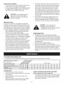
Read and follow the maintenance schedule and the maintenance procedures listed in this section.
MAINTENANCE
SCHEDULE
Fill in dates as you
complete regular service.
Check for loose fasteners
Check scraper and shoes for wear
Cleaning
Lubrication Section
/4 XY
x
x
Service Dates
x
X
X
LUBRICATION
Oil all pivot points on the snow thrower.
• Oil the pivot points of the two idler arms on the clutch/
idler assembly.
• Apply penetrating oil to the control cables of the
discharge chute.
• Apply a good grade of spray lubricant to the trigger
assembly and the chute tilt control assembly.
CHECK
SCRAPER
AND SHOES
FOR WEAR
(Refer to figures 59 and 60 on page 28.)
The scraper plate and skid shoes on the bottom of the
snow thrower are subject to wear. To prevent damage
to the spiral auger housing, replace plate and shoes
before wear is excessive.
27
CAUTION: Beforeservicing
oradjusting
thesnowthrower,
shutofftheengine,remove
thesparkplugwire(s),
settheparking
brake
andremove
thekeyfromthetractorignition.
REPLACING
•
AUGER
LiFT RELEASE
CABLE
ADJUSTMENT
If the lift rod does not lock the snow thrower securely
in the transport position, loosen the upper hex nut on
the lift bracket a few turns and tighten the lower hex
nut. Refer to figure 48 on page 22.
If the lift rod fails to unlock completely to lower the
snow thrower, loosen the lower hex nut on the lift
bracket a few turns and tighten the upper hex nut.
Refer to figure 48 on page 22.
BELT
Disengage the tractor's attachment clutch.
Lower the snow thrower to the ground.
Remove the attachment pin.
Lock the snow thrower's lift handle in the down
position to decrease belt tension.
Release the spring tension from the auger belt idler
arm on the bottom of the clutch/idler assembly.
Remove the auger drive belt from the clutch/idler
assembly and from the spiral auger housing.
Install new belt over top of large auger drive pulley
and under the two side idler pulleys. Twist the belt 1/4
turn to seat the "V" of the belt in the groove of each
idler pulley. Refer to figure 55 on page 24.
Assemble the belt onto the clutch/idler assembly.
CLUTCH
DISENGAGEMENT
ADJUSTMENT
(For tractors with engagement rod clutches only.
Not for electric clutches or cable clutches)
If the spiral auger on the snow thrower does not stop
when the attachment clutch lever on the tractor is
disengaged, then adjustment is necessary. Proceed as
follows. Refer back to figure 33 on page 17.
Place the attachment clutch lever in the disengaged
position.
Remove the hairpin cotter from the engagement rod
trunnion and lift the trunnion out of the hole in the idler
arm.
Screw the trunnion a few turns towards the front end
of the rod.
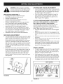
SKiD SHOE ADJUSTMENT
The skid shoes are mounted on each side of the spiral
auger housing. They regulate the distance the scraper
plate is raised above the plowing surface. When
removing snow from a gravel driveway or and uneven
surface, it is advisable to keep the scraper plate as
high above the surface as possible to prevent possible
damage to the spiral auger. On blacktop or concrete
surface, keep the scraper plate as close to the surface
as possible.
Raise the snow thrower off the ground and place a
block under each end of the scraper plate. Loosen the
six hex nuts securing the skid shoes to the housing.
Adjust the skid shoes up or down and retighten the
nuts securely. Adjust both skid shoes to the same
height to keep the housing and the scraper plate level.
See figure 59.
Replace the trunnion into the hole in the idler arm and
secure it with the hairpin cotter.
Check the operation of the snow thrower. If the spiral
augers still do not stop, repeat the above steps until
the augers stop when the attachment clutch lever is
placed in the disengaged position.
SPIRAL
AUGERS
The spiral augers are secured to the auger shaft with
two shear bolts and nylock nuts. If you hit a foreign
object or if ice jams the augers, the snow thrower is
designed so that the bolts will shear.
If the augers will not turn, check to see if the shear
bolts have sheared. See figure 60. Two replacement
shear bolts and nylock nuts have been provided with
the snow thrower. For future use order part number
710-0890A shear bolt and number 47810 nylock nut.
GEAR HOUSING
SKiD
SHOE
t
@
SHEAR BO_ AND
HEXLOCK NUT
FIGURE 59
FIGURE 60
28
SCRAPER
PLATE
SKiD
SHOE
STORAGE
•
REMOVING
*
RECOMMENDATIONS
PARTS TO REMOVE
Lower the snow thrower to the ground.
Remove the snow thrower from the tractor.
Clean the snow thrower thoroughly. Wash off any salt
deposit which may have dried on the thrower and
housing.
Any bare metal that has become exposed should be
painted or coated with a light oil to prevent rust.
Store in a dry place.
THE SPIRAL
AUGER
Remove the clutch/idler assembly. (The two hanger
brackets and the two shoulder bolts may be left
attached to the tractor frame.)
Remove the drive belt from the engine pulley.
If you replaced the engine pulley keeper on a manual
attachment clutch tractor, reinstall the tractor's original
engine pulley keeper. See figure 33 on page 17 or
figure 39 on page 19.
If you have a rod operated attachment clutch, remove
the engagement rod from the tractor's clutch arm. See
figure 29 on page 16.
If a front mounted attachment is to be used, remove
the side plates from the tractor. Be sure to assemble
bolts back into the empty holes in the tractor frame.
HOUSING
Lower the snow thrower to the ground.
Remove the attachment pin. See figure 54 on page
24.
Lock the snow thrower's lift handle in the down
position to decrease belt tension.
Release the spring tension from the auger belt idler
arm on the bottom of the clutch/idler assembly.
Remove the auger drive belt from the clutch/idler
assembly. See figure 56 on page 24.
Pull the spiral auger housing assembly off of the
tractor.
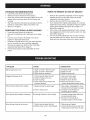
PROBLEM
AT END OF SEASON
CAUSE
CORRECTION
Spiral augers don't turn
1. Upper or lower V belt too loose
2. Upper or lower V belt broken
3. Shear bolts are sheared.
1. Increase tension on V belt
2. Replace V belt
3. Replace shear bolts
Clogged discharge chute
1. Tractor ground speed too fast
2. Tractor throttle set too low
1. Use lower tractor gear
2. Increase to full throttle
3. Raise the snow thrower
4. Allow snow thrower to cool to
outdoor temperature before using
3. Snow too deep
4. Snow melts during contact with
the snow thrower
Snow thrower stalls tractor engine
1. Object jammed in spiral auger
2. Hard or heavy snow
1. Stop engine, disengage the snow
thrower clutch and clear the auger
2. Increase to full throttle and
decrease ground speed
Front wheels slide instead of steering
Not enough traction at front wheels
1. Increase scraper plate clearance
by lowering skid shoes
2. Pull down on lift handle to
increase weight on front wheels
Snow thrower rides up over snow
1. Tractor ground speed too fast
2. Bottom snow is icy or hard packed
1. Reduce ground speed
2. Lower the skid shoes so that front
of skid shoe is lower than the rear
29
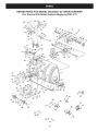
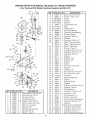
REPAIR PARTS FOR MODEL 486.24837 42" SNOW THROWER
(For Tractors With Model Numbers Beginning With 917)
4 tz,
3O
23
28
64
29
12
23
/
67"
537O
74
34
28
37
16
33
\
33
38
15
22
/
8
36
30
2O
32
9
23
66
X
4.4
23
61
49
27
16
35
\
30
23
23
58
18 41
27
6O
5O
47
65
/
21
5z
42
21
65
56
25
52
7
8
40, 59
40, 59 _¢_
54 _
3O
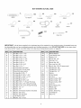
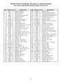
REPAIR PARTS FOR MODEL 486.24837 42" SNOW THROWER
(For Tractors With Model Numbers Beginning With 917)
REF
1
2
3
4
5
6
7
8
9
10
11
12
13
14
15
16
17
18
19
2O
21
22
23
24
25
26
27
28
29
30
31
32
33
34
35
36
37
38
PART NO
05931
65701
71464
63579
63768
24773
25982
703-2735A
24816
705-5226
705-5269
705-5270
43840
44950
44917
44326
43080
46703
710-0890A
43088
43070
47189
478! 0
715-0114
750-0437
731-1379A
43086
736-0188
711-0469
43081
47615
741-0309
741-0475
741-0493A
24279
48015
784-5618
24393
QTY
1
1
1
1
1
1
1
1
1
1
1
1
2
4
1
4
10
8
2
11
2
4
29
2
2
1
4
6
4
24
2
1
2
4
2
4
2
1
DESCRIPTION
REF
39
40
41
42
43
44
45
46
47
48
49
50
51
52
53
54
55
56
57
58
59
60
61
62
63
64
65
66
67
68
69
70
71
72
73
74
75
Housing, Bearing
Housing Assembly
Gear Assembly
Chute Crank Rod Assembly
Impeller Assembly
Scraper Plate
Shaft, Auger Gearbox
Bracket, Chute Crank
Cover, Belt
Chute Reinforcement
Spiral Assembly, L.H. (not shown)
Spiral Assembly, R.H.
Hex Bolt, 5/16-18 x 1-1/4" Lg.
Carriage Bolt, 1/4-20 x 3/4"
Palnut, 3/8"
Carriage Bolt, 5/16-18 x 1" Lg.
Carriage Bolt, 5/16-18 x 3/4" Lg.
Bolt, Self-Tap 5/16"x 3/4"
Bolt, Shear 5/16-18 x 1-1/2"
Washer, 1/4"
Washer, 3/8"
Hex Nut, 1/4-20 Nylock
Hex Nut, 5/16-18 Nylock
Spiral Pin, 1/4" x 1-1/2" Lg.
Bushing
Chute Adapter
Lock Washer, 5/16"
Washer, .76"x 1.49" x .06"
Spacer, .75 ID x 1.25 OD x .5 L
Washer, 5/16" Std. Wrt.
Bearing, Flange
Bearing, Ball
Bushing, Plastic 3/8"
Bearing, Split, 3/4"
Skid Shoe
Washer, Nylon
Housing, Bearing
Bracket, Chute Crank
31
PART NO
24281
49933
65367
65450
41576
44377
784-5594
746-0929
711-0242
746-0928
HA21362
43038
43343
43350
24394
47572
1643-60
64452
64451
47043
48106
24466
736-0247
47598
731-0921
731-1313C
47044
47026
43085
710-0896
731-0851A
43661
731-1300C
25937
HA20185
43182
40504
41361
QTY
1
2
1
1
2
1
1
1
1
1
4
2
2
4
1
6
1
1
1
1
4
2
1
6
1
1
2
1
1
1
3
6
1
1
1
3
1
1
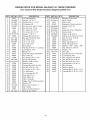
DESCRIPTION
Bracket, Idler
Shoulder Bolt, Round Head
Hanger Bracket Assembly, L.H.
Hanger Bracket Assembly, R.H.
Hex Bolt, 3/8-16 x 1-3/4"
Hex Bolt, 3/8-24 x 1"
Bracket, Cable
Cable, Chute Control With Clip
Spacer
Cable, Chute Control
Hex Nut, 3/8-16 Nylock
Pin, Pivot Lock
Pin, Hair Cotter #4 (1/8")
Carriage Bolt, 3/8-16 x 1"
Bracket, Chute Anti-rotation
Hex Lock Nut, 3/8-16 Flanged
Plastic Cap
Hanger Bracket Assembly', R.H.
Hanger Bracket Assembly, L.H.
Keeper, Engine Pulley
Bolt, Shoulder
Bracket, Down Stop
Washer,
Hex Lock Nut, 1/4" Flanged
Chute, Upper
Guide, Cable
Pulley, V Type 4"
Pulley, V Type
Hex Bolt, 5/16-18 x 1-1/2"
Screw, 1/4-14 x 5/8"
Chute Keeper
Hex Bolt, 1/4-20 x 1"
Chute, Lower
Center Brace, Gearbox
#61 Woodruff Key
Hex Bolt, 5/16-18 x 3/4"
Elevator Bolt, 1/4-20 x 1"
Owner's Manual
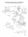
REPAIR PARTS FOR MODEL 486.24837 42" SNOW THROWER
(For Tractors With Model Numbers Beginning With 917)
41
40
45
\
52
47
51
5O
53
52
43
42
\
C
39
/
40
59
63
25
14
13
54
56
6
\
55
62
23
33
64
/
58
11
16
5
31
62
24
/
32
5
63
18
2O
65
65 58
57
60 !6 !6
35._.
3_
59--_
C
35
32
A
REPAIR PARTS FOR MODEL 486.24837 42" SNOW THROWER
(For Tractors With Model Numbers Beginning With 917)
REF
1
2
3
4
5
6
8
9
10
11
12
13
14
15
16
17
18
19
2O
21
22
23
24
25
26
27
29
30
31
32
33
34
35
36
37
38
39
4O
PART NO
64637
710-0865
710-0367
711-0332
712-0261
43262
142
43093
R19171616
43350
741-0192
783-0380
783-0381
24476
24311
47599
43086
24820
63773
48049
47369
732-0306
R19131316
47788
43080
43182
47368
46954
43343
25678
25679
49916
49912
43070
710-1233
46446
47027
741-0475
QTY
DESCRIPTION
1
2
2
2
2
6
5
1
4
6
2
2
2
2
1
2
4
1
1
1
1
1
2
2
1
2
1
1
1
1
1
1
Lift Shaft Assembly
Hex Bolt, 1/2-13 x 1"
Hex Bolt, 5/8-11 x 1-1/2"
Pin, Bracket Lift
Nut, Hex Lock 5/8-11 Thread
Nut, Hex Lock 1/2-13
Pin, Cotter 1/8"x 3/4"
Pin, Cotter 1/8"x 1-1/2"
Washer, 17/32"x 1"
Carriage Bolt, 3/8-16 x 1"
Bearing, Flange With Flats
Link, 15.80" Long
Link, 11.75" Long
Link, 4.88" Long
Rod, Spacer
Hex Bolt, 5/16-18 x 1" (Locking)
Lock Washer, 5/16"
Bracket, Lift
Assembly, Handle Lift Bracket
Rod, Index Lift
Pin, Spring 3/16" x 1-3/4"
Spring, Compression
Washer, 13/32" x 13/16"
Reflector, Rear
Carriage Bolt, 5/16-18 x 3/4"
Hex Bolt, 5/16-18 x 3/4"
Pin, Spring 5/16" x 1-3/4"
Pin, Attachment
Pin, Haircotter #4 (1/8")
Plate, Side (R.H.)
Plate, Side (L.H.)
Tube, Lift Handle
1
2
1
1
1
Trigger and Lift Cable Assembly
Washer, 3/8"
Screw, Oval #10-24 x 1"
Grip, Handle
Tube, Crank Rod Support
2
Bushing, 3/8" Plastic
33
REF
PART NO
QTY
41
42
43
45
46
47
48
49
50
51
52
53
54
55
56
57
58
59
60
61
62
63
64
65
66
67
68
69
703-2735A
720-0201A
44917
63579
784-5604A
720-04039
603-0302
731-1313C
746-0928
746-0929
43064
43081
24285
24284
43601
46584
R19172410
726-0178
47631
43003
47572
47810
43084
44326
48106
44695
43682
44215
1
1
1
1
1
1
1
1
1
1
5
2
1
1
1
1
8
3
6
6
6
8
2
2
2
2
2
2
DESCRIPTION
Bracket, Chute Crank
Knob, Crank
Palnut, 3/8"
Assembly, Chute Crank Rod
Handle, Chute Tilt
Knob
Assembly, Chute Tilt Bracket
Guide, Cable
Cable, Chute Control
Cable, Chute Control with Clip
Nut, Hex Lock 5/16-18
Washer, 5/16"
Plate, Mounting (L.H.)
Plate, Mounting (R.H.)
Washer, 1.59" x 1.032" x .060"
Nut, Whizlock, 5/16-18
Washer, 1/2"
Tie, Nylon
Hex Bolt, 3/8-16 x 1" Self Tap
Lock Washer, 3/8"
Nut, Flanged Lock 3/8-16
Nut, Nylock Hex 5/16-18
Hex Bolt, 5/16-18 x 1-3/4"
Carriage Bolt, 5/16-18 x 1"
Bolt, Shoulder
Washer, Bowed
Carriage Bolt, 5/16-18 x 1-1/4"
Carriage Bolt, 5/16-18 x 1-3/4"
REPAIR PARTS FOR MODEL 486.24837 42" SNOW THROWER
(For Tractors With Model Numbers Beginning With 917)
26
23
46
45--..._
41
39
38
.48
36
40 37
,14
12
17
12
17
57
3_
12
12
44
33
23
53
REF
1
2
3
4
5
6
7
8
9
10
11
PART NO
43080
43064
43083
43086
43081
26943
63904
24286
63762
43015
46981
QTY
2
3
2
4
20
1
1
1
1
1
1
DESCRiPTiON
Carriage Bolt, 5/16-18 x 3/4"
Hex Lock Nut, 5/16-18
Hex Nut, 5/16-18
Lock Washer, 5/16"
Washer, 5/16" Std. Wrt.
Frame, Clutch and Pulley
Idler Arm Assembly
Spacer, Pivot
Idler Bracket Assembly
Hex Nut, 3/8-16
Pulley, V Type 9"
34
REF
PART NO
QTY
DESCRiPTiON
12
43082
8
Nut, Hex Lock, 3/8-16
13
14
46982
738-0680
1
1
Pulley, VType
Shaft
15
16
17
18
19
20
21
22
23
24
25
750-0456
750-0660
43003
714-0161
741-0919
08253B
15296A
14088B
44377
736-0247
43063
1
1
6
2
2
1
1
1
2
2
3
Spacer
Spacer
Lock Washer, 3/8"
Key
Bearing, Ball
Housing, Bearing
Housing, Open Bearing
Spacer, Spindle
Hex Bolt, 3/8-24 x 1"
Washer
Hex Bolt, 5/16-18 x 1"
26
27
28
29
30
31
32
33
34
35
36
46989
48138
47846
47044
47025
43432
43054
24571
24472
43070
46959
46963
1
1
1
1
1
1
2
1
1
8
1
2
Belt, V Type Drive (55")
Belt, V Type Drive (56")
Belt, V Type Auger
Pulley, V Type 4"
Hex Bolt, 5/16-18 x 3-1/2"
Hex Bolt, 3/8-16 x 2-1/2"
Hex Bolt, 3/8-16 x 2"
Spacer
Spacer, Pivot
Washer, 3/8"
Spring
Chain
37
38
39
43055
23727
43088
1
1
1
Pin, Hair Cotter, 3/32"
Spacer
Washer, 1/4"
40
41
42
43343
47134
711-0198
2
2
1
Pin, Hair Cotter #4 (1/8")
Pin, Hair Cotter 5/64"
Trunnion
43
44
45
46
46948
47620
47607
23625
1
1
1
1
Rod, Engagement
Spring
Spring, Torsion
Spacer
47
48
49
43509
47605
24558
1
1
1
Hex Bolt, 3/8-16 x 2-3/4" Lg.
Washer, Flat 3/8"
Cable Bracket
50
51
52
49870
43178
43177
1
2
1
Hex Bolt, 1/4-20 x 2-1/2"
Hex Nut, 1/4-20
Lock Washer, 1/4"
53
54
55
48883
25728
46938
3
2
1
Pulley, Flat 3-5/8"
Rear Pulley Frame Bracket
Hex Bolt, 3/8-16 x 3-1/4"
56
57
58
59
60
25780
47810
43182
HA180132
43063
1
10
4
1
4
Spacer
Hex Nut,
Hex Bolt,
Hex Bolt,
Hex Bolt,
61
27016
2
Front Pulley Frame Bracket
5-1/2"
5/16-18 Nylock
5/16-18 x 3/4"
3/8-16 x 2-1/4"
5/16-18 x 1"
SUGGESTED GUIDE FOR SIGHTING
OF TRACTOR WITH ATTACHMENT
SLOPES FOR SAFE OPERATION
_FOLD ALONG D
THISISA _10 - OTTED LINE
SLo
ONLY RIDE UP AND DOWN
NOT ACROSS HILL
HILL,
LO
03
10 DEGREES
&
MAX.
WARNING: To avoid serious injury, operate your tractor up and
down the face of slopes, never across the face. Do not operate
on slopes greater than 10 degrees. Make turns gradually to
prevent tipping or loss of control. Exercise extreme caution
when changing direction on slopes. Braking may be affected by
tractor attachment. Reduce speed on slopes.
1. Fold this page along dotted line indicated above.
2. Hold page before you so that its left edge is vertically parallel to a tree
trunk or other upright structure.
3. Sight across the fold in the direction of hill slope you want to measure.
4. Compare the angle of the fold with the slope of the hill.
Your Home
For expert troubleshooting
and home solutions advice:
www.managemyhome.com
For repair - in your home - of all major brand appliances,
lawn and garden equipment, or heating and cooling systems,
no matter who made it, no matter who sold it!
For the replacement parts, accessories and
owner's manuals that you need to do-it-yourself.
For Sears professional installation of home appliances
and items like garage door openers and water heaters.
1-800-4-MY-HOME
Call anytime,
®
(1-800-469-4663)
day or night (U.S.A. and Canada)
Our Home
For repair of carry-in items like vacuums, lawn equipment,
and electronics, call anytime for the location of your nearest
Sears Parts & Repair Service
1-800-488-1222
(U.S.A.)
1-800-469-4663
www.sears.com
To purchase a protection
1-800-827-6655
agreement
on a product serviced by Sears:
1-800-361-6665
Para pedir servicio de reparaci6n
a domicilio, y para ordenar piezas:
® Marca
Trademark
Registrada
MC Marque
/ TMTrademark
/ TM Marca
1-800-LE-FOYER
®
de commerce
/ SMService
de F&brica
/ MD Marque
/ SM Marca
d6posee
(Canada)
Au Canada pour service en fran(_ais:
M°
(1-800-533-6937)
www.sears.ca
(1-888-784-6427)
® Registered
(Canada)
www.sears.ca
(U.S.A.)
1-888-SU-HOGAR
Center
Mark of Sears
de Servicio
de Sears
Brands,
Brands,
de Sears
LLC
LLC
Brands,
LLC
© Sears
Brands,
LLC
1