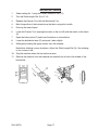
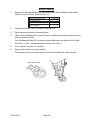
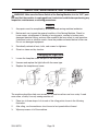
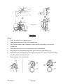
1
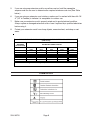
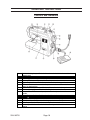
SEWING MACHINE
45 / 21 STITCH
90715
ASSEMBLY AND OPERATING INSTRUCTIONS
®
3491 MISSION OAKS BLVD., CAMARILLO, CA 93011
VISIT OUR WEB SITE AT HTTP://WWW.HARBORFREIGHT.COM
Copyright © 2003 by Harbor Freight Tools®. All rights reserved. No portion of
this manual or any artwork contained herein may be reproduced in any shape
or form without the express written consent of Harbor Freight Tools.
For technical questions and replacement parts, please call 1-800-444-3353
SPECIFICATIONS
Item
Pow er C onsum ption
Pow er C ord
Sew ing F unctions
Needle Positions
Fea tures
Acc essories
W eight
O verall D im ensions
D escrip tion
120 VA C, 60 Hz
T wo prong, polarized, 6 feet, UL lis ted, double
ins ulated
45 selec table stitch functions and 21 built-in
stitches, forward and revers e by select lever;
button func tion with built-in, one s tep button
holer
Left to extrem e rig ht
- B obbin w inder
- S titch length and width control
- A djustable thread and tension control
- B uilt-in acce ssory com partm ent
- E lectronic, variable sp eed foot con trol
- C an sew through multi-layered, light to
m edium heavy fa brics
- B uilt-in carrying handle
O iler, 3 needles, quilting guide, snap-on zigzag
foot; 3 bobbins, two screw drivers
18.7 lbs
8-5/8 x 13-1/2 x 17-1/4 inches
Note: This Sewing Machine is intended for household use.
SAVE THIS MANUAL
You will need the manual for the safety warnings and precautions, assembly instructions,
operating and maintenance procedures, parts list and diagram. Keep your invoice with this
manual. Write the invoice number on the inside of the front cover. Keep the manual and
invoice in a safe and dry place for future reference.
GENERAL SAFETY RULES
WARNING!
READ AND UNDERSTAND ALL INSTRUCTIONS. Failure to follow all instructions listed below may result in electric shock, fire, and/or serious injury.
SAVE THESE INSTRUCTIONS
Work Area
1.
Keep your work area clean and well lit. Cluttered benches and dark areas invite
accidents.
2.
Do not operate power machines in explosive atmospheres, such as in the presence of
flammable liquids, gases, or dust. Power machines create sparks which may ignite
the dust or fumes.
3.
Keep bystanders, children, and visitors away while operating a power machine.
Distractions can cause you to lose control. Protect others in the work area from
machine operation. Provide barriers or shields as needed.
SKU 90715
Page 2
Electrical Safety
4.
Avoid body contact with grounded surfaces such as pipes, radiators, ranges, and
refrigerators. There is an increased risk of electric shock if your body is grounded.
5.
Do not expose power machines to rain or wet conditions. Water entering a power
machine will increase the risk of electric shock.
6.
Grounded machines must be plugged into an outlet properly installed and grounded in
accordance with all codes and ordinances. Never remove the grounding prong or
modify the plug in any way. Do not use any adapter plugs. Check with a qualified
electrician if you are in doubt as to whether the outlet is properly grounded. If the
machines should electrically malfunction or break down, grounding provides a low
resistance path to carry electricity away from the user.
7.
This double insulated machine is equipped with a polarized plug (one blade is wider
than the other). This plug will fit in a polarized outlet only one way. If the plug does not
fit fully in the outlet, reverse the plug. If it still does not fit, contact a qualified electrician
to install a polarized outlet. Do not change the plug in any way. Double insulation
eliminates the need for the three wire grounded power cord and grounded power
supply system.
8.
Do not abuse the Power Cord. Never use the Power Cord to carry the machines or
pull the Plug from an outlet. Keep the Power Cord away from heat, oil, sharp edges, or
moving parts. Replace damaged Power Cords immediately. Damaged Power Cords
increase the risk of electric shock.
9.
When operating a power machine outside, use an outdoor extension cord marked “WA” or “W”. These extension cords are rated for outdoor use, and reduce the risk of
electric shock.
10.
Always connect the Line Cord to a Ground Fault Circuit Interrupter (GFCI) protected
electrical outlet.
Personal Safety
11.
Stay alert. Watch what you are doing, and use common sense when operating a
power tool. Do not use a power tool while tired or under the influence of drugs,
alcohol, or medication. A moment of inattention while operating power machines may
result in serious personal injury.
12.
Dress properly. Do not wear loose clothing or jewelry. Contain long hair. Keep your
hair, clothing, and gloves away from moving parts. Loose clothes, jewelry, or long hair
can be caught in moving parts.
13.
Avoid accidental starting. Be sure the Power Switch is off before plugging in.
Plugging in power tools with the Power Switch on, invites accidents.
14.
Remove adjusting keys or wrenches before turning the power machine on. A wrench
or a key that is left attached to a rotating part of the power machine may result in
personal injury.
SKU 90715
Page 3
15.
Do not overreach. Keep proper footing and balance at all times. Proper footing and
balance enables better control of the power tool in unexpected situations.
16.
Use safety equipment. Always wear eye protection.
Machine Use and Care
17.
Do not force the machine. Use the correct machine for your application. The correct
machine will do the job better and safer at the rate for which it is designed.
18.
Do not use the power machine if the Power Switch does not turn it on or off. Any
machine that cannot be controlled with the Power Switch is dangerous and must be
replaced.
19.
Disconnect the Power Cord Plug from the power source before making any
adjustments, changing accessories, or storing the machine. Such preventive safety
measures reduce the risk of starting the machine accidentally.
20.
Store idle machines out of reach of children and other untrained persons. Machines
are dangerous in the hands of untrained users.
21.
Maintain machines with care. Keep cutting tools sharp and clean. Properly
maintained tools with a sharp cutting edge are less likely to bind and are easier to
control. Do not use a damaged machine. Tag damaged machines “Do not use” until
repaired.
22.
Check for misalignment or binding of moving parts, breakage of parts, and any other
condition that may affect the machine’s operation. If damaged, have the machine
serviced before using. Many accidents are caused by poorly maintained machines.
23.
Use only accessories that are recommended by the manufacturer for your model.
Accessories that may be suitable for one tool may become hazardous when used on
another tool.
Service
24.
Machine service must be performed only by qualified repair personnel. Service or
maintenance performed by unqualified personnel could result in a risk of injury.
25.
When servicing a machine, use only identical replacement parts. Follow instructions
in the “Inspection, Maintenance, And Cleaning” section of this manual. Use of
unauthorized parts or failure to follow maintenance instructions may create a risk of
electric shock or injury.
SPECIFIC SAFETY RULES FOR THIS SEWING MACHINE
1.
Maintain labels and nameplates on the Sewing Machine. These carry important
information. If unreadable or missing, contact Harbor Freight Tools for a replacement.
2.
Always wear safety impact eye glasses. Using personal safety devices reduce the risk
for injury. Safety impact eye glasses are available from Harbor Freight Tools.
SKU 90715
Page 4
3.
Avoid unintentional starting. Make sure you are prepared to begin work before turning
on the Sewing Machine.
4.
Maintain a safe working environment. Keep the work area well lit. Make sure there is
adequate surrounding workspace. Always keep the work area free of obstructions,
grease, oil, trash, and other debris. Do not use a power machine in areas near
flammable chemicals, dusts, and vapors. Do not use this product in a damp or wet
location.
5.
Do not force the Sewing Machine. This machine will do the work better and safer at the
speed and capacity for which it was designed.
6.
Always unplug the Sewing Machine from its electrical outlet before changing needles
or settings, or performing inspection, maintenance, or cleaning procedures.
7.
Danger ! To reduce the risk of electric shock, never leave the Sewing Machine
unattended while turned on. Unplug this appliance from the electrical outlet
immediately after using and before cleaning.
8.
Before each use, check all nuts, bolts, and screws for tightness. Vibration during
mixing may cause these to loosen.
9.
Keep extension cord off the ground and away from water.
10.
Keep hands away from the needle when you turn the power switch on, or while the
machine is operating.
11.
Do not place your fingers into the thread take-up cover while the machine is
operating.
12.
Always turn the machine off and unplug the power cord to the electrical outlet before
tilting the machine head or removing the V-belt.
13.
Never leave the machine running and unattended.
14.
During operation, never place your head, hair, or hands in the proximity of the hand
wheel, V-belt, bobbin winder, or motor.
15.
Do not operate the machine with any safety guards removed.
16.
Always use the correct needle plate. The wrong plate can damage the needle.
17.
Never operate using a bent or broken needle.
18.
Never force the material in or out of the area being sewn. This can damage the needle.
19.
Warning: To reduce the risk of burns, fire, electric shock, or injury to persons:
A. Do not allow to be used as a toy. Close attention is necessary when this appliance
is used by or near children.
B. Use this appliance only for its intended use as described in this manual. Use only
attachments recommended by the manufacturer as contained in this manual.
SKU 90715
Page 5
C. Never operate this appliance if it has a damaged cord or plug, if it is not working
properly, if it has been dropped or damaged, or dropped into water. Take the product to
a certified service technician for examination, repair, electrical or mechanical
adjustment.
D. Never operate this appliance with any air openings blocked. Keep ventilation
openings free from the accumulation of lint, hair, loose clothes and dust.
E. Never drop or insert any object into any opening.
F. Do not use outdoors.
G. Do not operate where aerosol (spray) products are being used or where oxygen is
being administered.
H. Keep fingers away from all moving parts. Special care is required around the
sewing machine needle.
I. Always use the proper needle plate. The wrong plate can cause the needle to break.
J. Do not use bent needles.
K. Do not pull or push fabric while stitching. It may deflect the needle causing it to
break.
L. Switch the sewing machine off (O) when making any adjustments in the needle
area, such as threading needle, changing needle, threading bobbin, or changing
presser foot, etc.
M. Always unplug sewing machine from the electrical outlet when removing cover,
lubricating, or when making any other user servicing adjustments mentioned in the
instruction manual.
N.
Danger! Do not reach for an appliance that has fallen into water. Unplug
immediately.
O.
Danger! Do not place or store appliance where it can fall or be pulled into a tub
or sink. Do not place in or drop into water or other liquid.
P.
Warning! Never operate on a soft surface such as a bed or couch where the air
openings may be blocked.
WARNING! People with pacemakers should consult their physician(s) before using
this product. Operation of electrical equipment in close proximity to a heart pacemaker
could cause interference or failure of the pacemaker.
SKU 90715
Page 6
GROUNDING
WARNING!
Improperly connecting the grounding wire can result in the risk of electric
shock. Check with a qualfified electrician if you are in doubt as to whether the
outlet is properly grounded. Do not modify the power cord plug provided with
the tool. Never remove the grounding prong from the plug. Do not use the tool if
the power cord or plug is damaged. If damaged, have it repaired by a service
facility before use. If the plug will not fit the outlet, have a proper outlet installed
by a qualified electrician.
Double Insulated Tools: Tools with Two Prong Plugs
This Sewing Machine comes with a two-prong plug, and the electrical components inside
are double insulated for safety.
1.
Tools marked “Double Insulated” do not require grounding. They have a special double
insulation system which satisfies OSHA requirements and complies with the
applicable standards of Underwriters Laboratories, Inc., the Canadian Standard
Association, and the National Electrical Code.
5.
Double insulated tools may be used in either of the 120 volt outlets shown below.
EXTENSION CORDS
1.
Grounded tools with a three-prong plug require a three wire extension cord. Double
Insulated tools can use either a two or three wire extension cord.
2.
As the distance from the supply outlet increases, you must use a heavier gauge
extension cord. Using extension cords with inadequately sized wire causes a serious
drop in voltage, resulting in loss of power and possible tool damage. (See Table on
page 7.)
3.
The smaller the gauge number of the wire, the greater the capacity of the cord. For
example, a 14 gauge cord can carry a higher current than a 16 gauge cord.
4.
When using more than one extension cord to make up the total length, make sure
each cord contains at least the minimum wire size required.
SKU 90715
Page 7
5.
If you are using one extension cord for more than one tool, add the nameplate
amperes and use the sum to determine the required minimum cord size. (See Table
below.)
6.
If you are using an extension cord outdoors, make sure it is marked with the suffix “WA” (“W” in Canada) to indicate it is acceptable for outdoor use.
7.
Make sure your extension cord is properly wired and in good electrical condition.
Always replace a damaged extension cord or have it repaired by a qualified electrician
before using it.
8.
Protect your extension cords from sharp objects, excessive heat, and damp or wet
areas.
RECOM MENDED MINIM UM W IRE G AUG E FOR EXTENSION CORDS*
(120 VO LT )
NAM EPL ATE
AM PERE S
(At Full Load)
EX TENS IO N CO RD LE NG TH
25
50
75
100
150
Feet
Feet
F eet
Feet
F eet
0 – 2.0
18
18
18
18
16
2.1 – 3.4
18
18
18
16
14
3.5 – 5.0
18
18
16
14
12
5.1 – 7.0
18
16
14
12
12
7.1 – 12.0
18
14
12
10
12.1 – 16.0
14
12
10
16.1 – 20.0
12
10
* Based on lim iting th e line voltage d ro p to five volts at 150% of the ra ted am peres.
SYMBOLOGY
SKU 90715
Page 8
UNPACKING
When unpacking, check to make sure that all the parts are included. Refer to the Accessories listed below and the Controls and Indicators section.
If any parts are missing or broken, please call Harbor Freight Tools at the number on the
cover of this manual as soon as possible.
Accessories
1.
2.
3.
4.
5.
6.
7.
8.
9.
SKU 90715
Buttonhole Foot
Zipper Foot
Button Sewing Foot
Needle Pack (3 pcs.)
Bobbins (3 pcs.)
Darning Plate
Two screwdrivers (not shown)
Extra Spool Pin
Spool Holder (Large and Small)
Page 9
OPERATING INSTRUCTIONS
Controls and Indicators
1.
2.
3.
4.
5.
6.
7.
8.
9.
10.
11.
12.
13.
14.
15.
SKU 90715
Bobbin Winding Assy. – Winds the thread onto the bobbin to be used for the
lower thread
Spool Holder – Holds the sewing thread
Stitch Length Dial – Controls the length of the stitches
Presser Foot Lever – Raises and lowers the presser foot
Upper Tension Control Dial – Controls the tension of the upper thread
Extension Table and Accessories Compartment – Converts from the free-arm
into a flat bed machine
Mechanical Pattern Indication Window – Shows the stitch to be performed
Reverse Sewing Button – Push for stitching in the reverse direction
Balance Wheel – Turn toward you (counterclockwise) to raise and lower the
needle
Clutch Release Switch – Switches from bobbin winding mode to sewing mode
Pattern Selection Dial – Turn in either direction to select the desired stitch
(1)
Foot Controller Receptacle – Receives the foot controller plug
Foot Controller – Used to control sewing speed, start and stop
Main Power Switch – Turns the machine power on and off
Vertical Spool Holder – Used to hold a second spool of thread for twin needle
sewing
Page 10
Sewing Steps
Follow these basic steps to setup the sewing machine. Refer to the illustration on the previous page to locate the components referred to below.
1.
Set the Sewing Machine on a table with a smooth surface.
2.
Select and install the desired needle for the material to be sewn (See below).
3.
Place the spool of thread onto the Spool Holder (2) and route the thread from the spool
holder down to, and through the needle (See page 11).
4.
Wind the bobbin with thread (See page 13), place bobbin into the bobbin case, and
route the thread (page 12).
5.
Select the desired stitch pattern and length (See page 15).
6.
Replace the Presser Foot if necessary for sewing special items (See page 14).
7.
Insert the Foot Controller connector into the machine receptacle, then the line cord
plug into an electrical outlet (See page 9 ). Place the Foot Controller on the floor.
8.
Press the Main Power Switch (14) to the On (I) position.
9.
Press down slowly on the Foot Controller and sew a scrap piece of cloth for a few
minutes to test the machine.
10.
Periodically clean machine parts (See page 19).
11.
Periodically oil the machine (See page 18).
Replacing the Needle
1.
Unplug the line cord from the electrical outlet.
2.
Turn the Balance Wheel (9) to raise the needle to its
highest position.
3.
Lower the Presser Foot by pressing down on the Presser
Foot Lever (4).
4.
Loosen the Needle Clamp and pull the needle down and
out.
5.
Insert a new needle as far up as possible and against the
needle stopper. The needle’s flat side must face toward the back.
The needle must not be bent or broken. For general sewing, use needle sizes 11 or
14. A fine thread and needle should be used for sewing lightweight fabrics, so the
fabric will not be marred. Heavy fabrics require a needle large enough to pierce the
fabric without fraying the needle thread.
6.
Tighten the Needle Clamp.
SKU 90715
Page 11
Spool Threading
1.
Raise the Presser Foot with the Presser Foot Lever (4).
2.
Turn the Balance Wheel (9) counterclockwise to raise the needle to its highest
position.
3.
Place a spool of thread on the horizontal spool pin and press a spool holder onto the
spool pin to hold the thread spool firmly in place.
4.
Route the thread through the thread take-up lever from left to right, and down to the
needle.
Horizontal Spool Pin
Thread Take-up Lever
Spool Holder
(4)
Using the Needle Threader
1.
Lower the Presser Foot using Lever (4).
2.
Lower the Needle Threader (A) slightly and place the thread under the Guide (B).
3.
Move the Needle Threader down to its lowest position, then guide the thread under the
Hook (C) which passes through the eye of the needle.
4.
Release the Needle Threader and the thread at the same time. This will move the
thread through the needle eye. Pull two inches of thread through the needle.
SKU 90715
Page 12
Bobbin Placement and Threading
1.
Turn the Balance Wheel (9) counterclockwise to raise the needle to its highest
position.
2.
Raise the Presser Foot with its Lever (4).
3.
Remove the Extension Table (6), and then the shuttle cover (located on front of the free
arm).
4.
Remove the Bobbin Case by grasping the Bobbin Case Latch (A) and pulling it out.
See illustration below.
5.
Unwind about four inches of thread from the full Bobbin and insert the Bobbin into the
Bobbin Case.
6.
Pull the trailing thread into the slot, down and to the left, until it enters the delivery eye
under the tension spring (C).
7.
Holding the Bobbin Case by the Latch (A), insert the Bobbin Case into the shuttle
race and release the Latch. The Bobbin Case Finger (B) must fit into the Notch (E) at
the top of the race.
Bobbin Case
8.
Raise the Presser Foot and needle to their highest positions.
9.
With your left hand, hold the end of the upper thread (F). With
your right hand, turn the Balance Wheel (9) counterclockwise
until the needle moves down and back up again to its highest
position. The upper thread should have caught the lower
thread in a loop.
10.
Pull the upper thread toward you and the lower thread (G) will
come up from the bobbin in a large loop.
11.
Pull out about six inches of both threads and place them
between the toes of the Presser Foot and to the right and back of the Presser Foot.
SKU 90715
Page 13
Bobbin Winding
1.
Change the Clutch Release Switch (10) from the needle mark to the bobbin mark.
2.
With a spool of thread already on the horizontal spool pin, route the thread through the
guide to the bobbin as shown below.
3.
Place the bobbin onto the bobbin winder shaft (B) and slide the shaft to the right. Turn
the bobbin clockwise until the spring (C) on the shaft slides into the slit on the bobbin.
4.
Hold the end of the thread from the bobbin and gently press the Foot Controller (13) to
begin winding thread around the bobbin a few times as shown below. Release the
Foot Controller.
5.
Trim the excess thread above the bobbin and continue winding the thread onto the
bobbin. The machine will automatically stop when the bobbin is full.
6.
Cut the thread, push the bobbin winder shaft to the left, and remove the full bobbin
from the shaft.
7.
Return the Clutch Release Switch (10) back to the needle mark.
Slide to right
SKU 90715
Page 14
Changing the Presser Foot
1.
Turn the Balance Wheel (9) counterclockwise to raise the needle to its highest
position.
2.
Raise the Presser Foot with its Lever (4).
3.
Release the Foot by raising its lever (A) located at the back of the holder.
4.
Place a different Presser Foot on the needle plate so that the bar on the Presser Foot
is in line with the slot on the shank (B).
5.
Lower the Presser Foot lever to fix the Presser Foot onto the shank.
If the Presser Foot is in the correct location, the bar should snap in place.
(B)
(A)
Converting to Free-arm Style
Free-arm sewing is convenient for sewing tubular and hard-to-reach areas on a garment.
To change the machine to free-arm operation, remove the Extension Table (6).
1.
Lift up on the Extension Table (6).
2.
Slide the Extension Table to the left.
SKU 90715
Page 15
Selecting a Stitch Pattern and Stitch Length
To select a stitch, turn the Pattern Selection Knob (11). The selection knob may be turned in
either direction. All stitches are preset in width, therefore, the stitch length is the only other
necessary adjustment.
1.
Turn the Balance Wheel (9) counterclockwise to raise the needle to its highest
position.
2.
Turn the Pattern Selection Knob to select the desired stitch pattern. The selection will
appear in the Mechanical Pattern Indication Window Version (7) on the front of the
machine.
3.
To set the stitch length, turn the Stitch Length Dial (3),
counterclockwise for a shorter stitch (lower number), clockwise for a
longer stitch (higher number). See Table below.
Depending on the selected stitch, it may be necessary to adjust the
stitch length for best results. The dial also adjusts upper thread
tension. The “O” setting does not feed the material. This is used for
sewing on a button. The “F” area is used for making a Satin Stitch (a
close zigzag stitch).
Pattern
1
2
3
4
5
6
7
8
9
10
11
12
13
14
15
16
17
18
19
20
21
SKU 90715
Stitch Name
1-Step Automatic Buttonhole
Straight Stitch (left needle position)
Straight Stitch (center needle position)
Zigzag Stitch
Zigzag Stitch
Zigzag Stitch
Blind Hem Stitch
Shell Tuck Stitch
Elastic Stitch
Stretch Blind Stitch
Double Action Stitch
Scallop Stitch
Lightning Stitch
Bead Stitch
Fagoting Stitch
Arrowhead Stitch
Feather Stitch
Slant Overlock Stitch
Elastic Overlock Stitch
Triple Zigzag Stretch Stitch
Triple Stretch Stitch
Page 16
Preset Width
5 mm; 13/64"
0
0
1.5 mm; 1/16"
3.5 mm; 9/64"
5 mm; 31/64"
3 mm; 1/8"
5 mm; 13/64"
5 mm; 13/64"
3 mm; 1/8"
5 mm; 13/64"
5 mm; 13/64"
5 mm; 13/64"
5 mm; 13/64"
5 mm; 13/64"
5 mm; 13/64"
5 mm; 13/64"
5 mm; 13/64"
5 mm; 13/64"
5 mm: 13/64"
0
Recommended Length
F-1/5 mm; 1/64-1/16"
1-4 mm; 3/64-5/32"
1-4 mm; 3/64-5/32"
F-4 mm; 1/64-5/32"
F-4 mm; 1/64-5/32"
F-4 mm; 1/64-5/32"
F-2 mm; 1/64-5/64"
F-3 mm; 1/64-1/8"
F-2.5 mm; 1/64-3/32"
F-1.5 mm; 1/64-1/16"
F-3 mm; 1/64-1/8"
F-1.5 mm; 1/64-1/16"
F-1 mm; 1/64-3/64"
F-1 mm; 1/64-3/64"
Fixed 2.5 mm; 3/32"
Fixed 2.5 mm: 3/32"
Fixed 2.5 mm: 3/32"
Fixed 2.5 mm; 3/32"
Fixed 2.5 mm: 3/32"
Fixed 2.5 mm; 3/32"
Fixed 2.5 mm: 2/32"
Buttonhole Sewing
1.
Select setting No. 1 using the Pattern Selection Dial (11).
2.
Turn the Stitch Length Dial (3) to F-1.5.
3.
Replace the Presser Foot with the Buttonhole Foot.
4.
Mark the position of the buttonhole on the fabric using tailor’s chalk.
5.
Draw up the lower thread.
6.
Lower the Presser Foot, aligning the marks on the foot (B) with the marks on the fabric
(A).
7.
Open the button plate (C) and insert the button as shown below.
8.
Lower the buttonhole lever (D) and push it back slightly.
9.
While gently holding the upper thread, start the machine.
Buttonhole stitching is sewn clockwise. Adjust the Stitch Length Dial (3) if the stitching
is too course or fine.
10.
Stop the machine when the bar tacks are sewn.
11.
Remove the material from the machine and carefully cut a hole in the middle of the
buttonhole.
SKU 90715
Page 17
Button Sewing
1.
Measure the distance between the button holes and select the appropriate pattern
number using the Pattern Selection Dial (11).
Distance between holes
1.5 mm (1/16”)
Pattern No.
4
3.5 mm (9/16”)
5
5 mm (13/64”)
6
2.
Change the Presser Foot to the Button Sewing Foot.
3.
Place the darning plate on the needle plate.
4.
Place a button between the foot and the fabric, aligning the thread holes in the button
with the machine needle.
Turn the Balance Wheel (9) to make sure the needle enters the holes without hitting
the button. If it hits, change the pattern number (see step 1).
5.
At slow speed, sew about 10 stitches.
6.
Remove the material from the machine.
Cut the upper and lower threads and tie both threads at the back of the material.
Button Sewing Foot
SKU 90715
Page 18
INSPECTION, MAINTENANCE, AND CLEANING
WARNING! Make sure the Power Switch of the Sewing Machine is in its “OFF” position and that the machine is unplugged from its electrical outlet before performing any
inspection, maintenance, or cleaning procedures.
General
1.
Any repairs must be completed by an experienced sewing machine technician.
2.
Before each use, inspect the general condition of the Sewing Machine. Check for
loose screws, misalignment or binding of moving parts, cracked or broken parts,
damaged electrical wiring, and any other condition that may affect its safe operation.
If abnormal noise or vibration occurs, have the problem corrected before further use.
Do not use damaged equipment.
3.
Periodically recheck all nuts, bolts, and screws for tightness.
4.
Store in a clean and dry location.
Changing the Light Bulb
1.
Loosen the faceplate screw and pull off the face plate.
2.
Unscrew and replace the light bulb with the same type.
3.
Replace the faceplate and screw.
Oiling
The machine should be oiled once a week if it is used more than one hour a day. If used
more often, oil daily. Use only sewing machine oil.
1.
Place two to three drops of oil at each of the oiling points shown in the following
illustration.
2.
After oiling, run the machine a short time at a fast speed without thread.
3.
Wipe any excess oil off the machine.
SKU 90715
Page 19
Oiling Points
Cleaning
Shuttle
1.
Raise the needle to its highest position.
2.
Open the shuttle cover on the front of the free arm.
3.
Take out the bobbin case by opening its latch lever (B) and pulling it out from the
shuttle race.
4.
Slide the latch levers out from the retaining ring (A) and remove.
5.
Remove the hook by grasping the center post of the hook and pulling it out.
6.
Remove any lint and thread from the retaining ring, hook (C), driver (D) and race body
(E) with a brush and small vacuum.
7.
Reverse steps 1-6 to reassemble.
SKU 90715
Page 20
Feed Dogs
1.
Remove the needle plate using a coin to unscrew the screws.
2.
Clean the upper part of the feed dogs and shuttle race body with a brush.
PLEASE READ THE FOLLOWING CAREFULLY
THE MANUFACTURER AND/OR DISTRIBUTOR HAS PROVIDED THE PARTS DIAGRAM IN THIS
MANUAL AS A REFERENCE TOOL ONLY. NEITHER THE MANUFACTURER NOR DISTRIBUTOR MAKES ANY REPRESENTATION OR WARRANTY OF ANY KIND TO THE BUYER THAT HE
OR SHE IS QUALIFIED TO MAKE ANY REPAIRS TO THE PRODUCT OR THAT HE OR SHE IS
QUALIFIED TO REPLACE ANY PARTS OF THE PRODUCT. IN FACT, THE MANUFACTURER
AND/OR DISTRIBUTOR EXPRESSLY STATES THAT ALL REPAIRS AND PARTS REPLACEMENTS
SHOULD BE UNDERTAKEN BY CERTIFIED AND LICENSED TECHNICIANS AND NOT BY THE
BUYER. THE BUYER ASSUMES ALL RISK AND LIABILITY ARISING OUT OF HIS OR HER
REPAIRS TO THE ORIGINAL PRODUCT OR REPLACEMENT PARTS THERETO, OR ARISING
OUT OF HIS OR HER INSTALLATION OF REPLACEMENT PARTS THERETO.
SKU 90715
Page 21
PART LISTS AND ASSEMBLY DRAWINGS
NOTE: Some par ts are listed and shown for illustration purposes only and are not available
individually as replacement parts.
1 - Machine Frame Mechanism
SKU 90715
Page 22
SKU 90715
Page 23
2 - Cover
SKU 90715
Page 24
SKU 90715
Page 25
3 - Needle Bar Mechanism
SKU 90715
Page 26
4 - Cloth Presser Mechanism
SKU 90715
Page 27
5 - Buttonhole Regulator Mechanism
SKU 90715
Page 28
6 - Driving Mechanism
SKU 90715
Page 29
SKU 90715
Page 30
7 - Thread Adjusting Mechanism
SKU 90715
Page 31
SKU 90715
Page 32
8 - Stitch Length Adjusting Mechanism
SKU 90715
Page 33
SKU 90715
Page 34
9 - Pattern Selection Mechanism
SKU 90715
Page 35
SKU 90715
Page 36
10 - Feed Mechanism
SKU 90715
Page 37
SKU 90715
Page 38
11 - Reverse Feed Mechanism
SKU 90715
Page 39
12 - Shuttle Lower Shaft Mechanism
SKU 90715
Page 40
SKU 90715
Page 41
13 - Accessories
13-16
PARTS LIST
ITEM # DESCRIPTION
12-15 Bobbins (3)
13-1.0 Seam Pressure Foot
13-2.0 Cloth Guard Adjusting Plate
13-3.0 Buttonhole Pressure Foot
13-4.0 Straight Serving Pressure Foot
13-5.0 Zipper Pressure Foot
13-6.0 Button Pressure Foot
13-7.0 Thread Bushing
13-8.0 Thread Dial
ITEM # DESCRIPTION
13-9.0 Sewing Dial
13-10 Thread Dial Holder
13-11 Big Screwdriver
13-12 Small Screwdriver
13-13 Bottle
13-14 Knife
13-15 Top Thread Winder
13-16 Foot Controller
WIRING DIAGRAM
Pedal Controller
o
o
Light Switch
M
X
SKU 90715
Lamp
Page 42
Motor