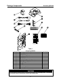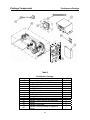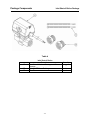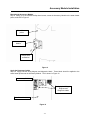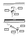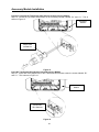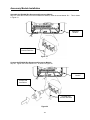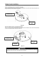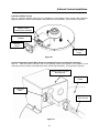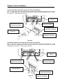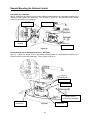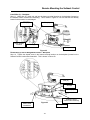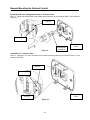
1
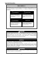
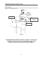
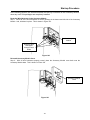
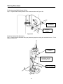
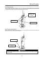
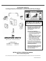
ACCESSORY MODULE Including Protection, Performance, and Inlet Shut-off Valve Packages This manual must be used in conjunction with the Installation and Operation Manual for the water heater. Ambler, PA 19002 www.bradfordwhite.com Tech. Service ..........................(800) 334-3393 Service Parts ..........................(800) 538-2020 Warranty Department .............(800) 531-2111 - Do not store or use gasoline or other flammable vapors and liquids in the vicinity of the water heater or any other appliance - What to do if you smell gas: • Do not try to light any appliance. • Do not touch any electrical switch; do not use any phone in your building. • Immediately call your gas supplier from a neighbor phone. Follow the gas supplier instructions. • If you cannot reach your gas supplier, call the fire department. - For your family comfort, safety and convenience, it is recommended these packages be installed and serviced by a plumbing professional. - Read and understand the water heater manual before installing or operating the Accessory Module and its associated packages. INSTALLATION & OPERATION MANUAL With Troubleshooting Guide PLACE THESE INSTRUCTIONS ADJACENT TO WATER HEATER AND NOTIFY OWNER TO KEEP FOR FUTURE REFERENCE 238-47878-00B 04/10 Important Information CONGRATULATIONS! You have just purchased one of the finest water heater accessories on the market today! This Installation and Operation Manual will explain in detail how to install and operate your new Accessory Module, as well as the packages that can be connected to the Accessory Module. We strongly recommend you contact a plumbing professional for the installation of this new control. We require that you carefully read this manual and your water heater manual and refer to them when questions arise. If you have any specific questions concerning your warranty, please consult the plumbing professional from whom your Accessory Module was purchased. For your records, we recommend that you write the installation date for these accessories in the back of this manual. This manual should be kept with the Accessory Module. NOTICE The Accessory Module and its associated packages are for use only with Bradford White water heaters equipped with compatible Honeywell gas controls. The Accessory Module is always required in order to use the Protection, Performance, and/or the Inlet Shut-off Valve Packages. The Protection Package is required in order to use the Inlet Shut-off Valve Package. For easier installation, the Integrated Mixing Device and Inlet Shut-off Valve should be installed first. Accessory Module: The Accessory Module is an electronic component that allows the water heater gas control to be connected to the Protection, Performance, and Inlet Shut-off Valve Packages. Accessory Module: Contains: o Wire holders o Accessory Module o Wire ties o Plug-in transformer o Installation & Operation Manual o Transformer wire harness o Screws o (2) gas control harnesses (only (1) used per water heater) Features: o Multi-color LED used to display status and diagnostics o Audible alarm to sound in the event a fault occurs o Easily mounts to the water heater or can be remote mounted o One Accessory Module fits all diameter water heaters o Durable construction -2- Important Information Protection Package (sold separately): Contains: o Leak sensor (2 piece) o Wire holders o Dam o Wire ties o Leak sensor wire harness o Screws Features: o Senses a collection of water near the water heater o Sounds the alarm to alert homeowners when a water heater leak is detected and verified o Alarm is re-settable and can be temporarily silenced o Durable construction o Easy installation – all wiring is provided o Can be used without the need for a water heater drain pan o Includes dam, which corrals the water in order for the leak to be detected Performance Package (sold separately): Contains: o Integrated Mixing Device (IMD) o Setback Control Mixing valve o Setback Control Junction Box Cold water tee Assembly (2) flexible connectors (only o Setback Control wire harness (1) used per water heater) o Wire ties Thermo-strip o Screws Setback Control Features: o 7 day / 4 period programming o Conserves energy o Hot water capacity indicator (provides an estimate of available hot water) o Battery back-up stores programming during a power outage o Can be programmed to comply with Sabbath requirements o Similar interface to furnace / air conditioning thermostats o Precision control of water temperature Integrated Mixing Device Features: o Push to turn handle o Thermo-strip to indicate approximate outlet water temperature o Port to draw off tank temperature water o Port to return recirculation water into the mixing valve o Port on cold water tee to draw off water for use without installing a saddle valve o Allows water in the tank to be stored at higher temperatures while controlling the hot water outlet temperature at a safe and comfortable level o Precision control of water temperature Inlet Shut-off Valve (sold separately): Contains: o Inlet shut-off valve with o (2) 3/4” to 1” NPT bushing integrated wire harness o Wire ties Features: o Shuts off water supply to the water heater in the event a water heater tank leak is detected o Solid brass construction o Robust design o Easy wiring with integral wire harness o Mounts directly to the water heater inlet o Can be used on both 3/4” and 1” NPT inlet fittings -3- Important Information READ CAREFULLY The following terms are used throughout this manual to bring attention to the presence of hazards at various risk levels, or to important information concerning product life. DANGER CAUTION Indicates an imminently hazardous situation, which, if not avoided, will result in death, serious injury or substantial property damage. Indicates potentially hazardous situation, which, if not avoided, may result in moderate or minor injury or property damage. WARNING NOTICE Indicates special instructions on installation, operation or maintenance, which are important but not related to personal injury hazards. Indicates a potentially hazardous situation, which, if not avoided, could result in death, serious injury or substantial property damage. DANGER Hotter water increases the risk of scald injury. Scalding may occur within five (5) seconds at a temperature setting of 140°F (60°C). To protect against hot water injury, install an ASSE approved mixing valve in the water system. This valve will reduce point of discharge temperature by mixing cold and hot water in branch water lines. A licensed plumbing professional or local plumbing authority should be consulted. NOTICE The water heater is equipped with an energy cut out device to prevent overheating. Should overheating occur or the gas supply fails to shut off, turn off the manual gas control valve to the water heater and call a qualified service technician. Whenever the water heater is filled with cold water, condensate will form on the cool tank surface and drops of water will fall on the hot burner and combustion chamber surfaces producing a “sizzling” noise. Condensation is normal and does not indicate a leak. It will disappear when the tank becomes heated. CAUTION The water heater, when set at a lower temperature setting, is not capable of producing hot water of sufficient temperature for sanitizing purposes. -4- Important Information NOTICE The lower the temperature setting, the greater the energy efficiency, both to heat the water and to maintain the storage temperature during standby periods. Lower water temperatures also extend tank life. Remember, no water heating system will provide exact temperatures at all times. Allow a few days of operation at this setting to determine the correct temperature setting consistent with the requirements for the installation. WARNING Do not operate the water heater or Accessory Module without the Accessory Module cover in place. Do not operate the water heater or Setback Control without the Setback Control Junction Box Assembly cover in place. Do not operate water heater, Accessory Module, and Setback Control with jumpered or absent controls or safety devices. Turn off or disconnect the electrical power supply to the water heater and its accessories before servicing. Label all wires prior to disconnection when servicing controls. Wiring errors can cause improper and dangerous operation. Verify proper operation after servicing. All electrical wiring must be installed and grounded in accordance with local codes, or in the absence of local codes, the National Electrical Code, ANSI/NFPA 70 and/or CSA C22 Electrical Code. Do not use wire holders to the right of the water heater gas valve. The screws used for the wire holders can damage the water heater internal components. For energy efficient operation of your water heater, the suggested initial water temperature setting is 120˚F (49˚C). During the winter season, or any cold period, you may desire a higher water temperature setting to adjust for the colder incoming water. This adjustment, however, may cause additional condensation to form on the cooler tank surface. This does not mean the tank is leaking. During summer months, the warmer incoming water temperatures will benefit the performance of your water heater and reduce the amount of condensation developed. Condensation does not mean your tank is leaking. Over 40% of reported tank leaks on installation are proven to be condensation. To avoid unnecessary expense and inconvenience, make sure the tank is leaking before calling a service technician. Water temperature over 125°F can cause severe burns instantly or death from scalds. Children, disabled and elderly are at highest risk of being scalded. Review this instruction manual before setting temperature at water heater. Feel water before bathing or showering. Temperature limiting valves are available. -5- Table of Contents Page Tools Required............................................................................................ 7 Package Components................................................................................. 8 Accessory Module ........................................................................... 8 Protection Package ......................................................................... 9 Performance Package..................................................................... 10 Inlet Valve Shut-off Package ........................................................... 11 Wiring Diagram ........................................................................................... 12 Accessory Module Installation..................................................................... 13 Setback Control Installation ........................................................................ 27 Integrated Mixing Device - IMD ................................................................... 39 Leak Sensor Installation.............................................................................. 40 Inlet Shut-off Valve Installation.................................................................... 49 Remote Mounting the Setback Control ....................................................... 56 Start-up Procedure...................................................................................... 67 Diagnostic Codes ........................................................................................ 73 Notes........................................................................................................... 74 Warranty...................................................................................................... 75 -6- Tools Required Slotted Screwdriver Philips Screwdriver 1/8” Drill bit Drill Needle nose pliers Pipe dope Adjustable wrench Caulk gun RTV sealant (silicone) Pipe cutter Propane torch Solder Flux Wire Cutters Wire Strippers Fine Point Marker -7- Package Components Accessory Module ACCESSORY MODULE DIAGNOSTIC CODES FOR USE WITH THE FOLLOWING GAS VALVES: 222-47463-01 222-47463-02 222-47464-01 222-47464-02 222-47465-01 222-47465-02 222-47466-01 222-47466-02 222-46402-01 222-46402-02 222-46990-01 222-46990-02 222-46991-01 222-46991-02 LED STATUS COLOR GREEN ACCESSORY MODULE R1 C1 BK LK C2 NO NC D/1 R/2 C/3 A1 A2 BK BL BR BK R BK W BK Y W R BK W R ACCESSORY MODULE STATUS PATTERN LED on continuously. Power on (no fault). One flash and three second pause. Leak alarm fault. Water shut-off valve open. Two flashes and three second pause. Leak alarm fault. Water shut-off valve closed. AMBER Three flashes and three second pause. Anode depletion alarm or not connected. AMBER Four flashes and three second pause. Leak sensor malfunction. AMBER Five flashes and three second pause. Gas valve missing/not connected. LED strobe (quick flashes). Hardware error. RED RED RED See Installation and Operation Instruction Manual for probable causes associated with each control status code. 238-47879-00A *WHEN CONNECTING LEAK SENSOR, REMOVE RESISTOR BETWEEN C1 & LK. **WHEN CONNECTING ANODE DEPLETION SENSOR, REMOVE RESISTOR BETWEEN A1 & A2. SEE INSTALLATION AND OPERATION MANUAL FOR MORE INFORMATION. FOR USE WITH THE FOLLOWING GAS VALVES: 222-45613-01 222-45613-02 222-45614-01 222-45614-02 ACCESSORY MODULE R BK W R1 C1 BK LK C2 NO NC D/1 R/2 C/3 A1 A2 BK BL BR BK R BK W BK Y D R C W R *WHEN CONNECTING LEAK SENSOR, REMOVE RESISTOR BETWEEN C1 & LK. **WHEN CONNECTING ANODE DEPLETION SENSOR, REMOVE RESISTOR BETWEEN A1 & A2. SEE INSTALLATION AND OPERATION MANUAL FOR MORE INFORMATION. 238-47880-00A Table 1 1A 2A 3A 4A 5A 6A 7A 8A 9A 10A 11A Accessory Module Description Plug-in Transformer WV4460 Wire Harness Transformer Wire Harness WV8840 Wire Harness Wire Holders Installation & Operation Manual Wiring Diagram Label Diagnostic Label Wire Ties Screws Accessory Module Quantity 1 1 1 1 4 1 1 1 4 9 1 NOTICE The WV4460 wire harness must be used with gas controls with intermittent pilots. The WV8840 wire harness must be used with gas controls with standing pilots. -8- Package Components Protection Package Table 2 1B 2B 3B 4B 5B 6B 7B Protection Package Description Leak Sensor Bracket Leak Sensor Housing Dam Screws Leak Sensor Wire Harness Wire Holders Wire Ties -9- Quantity 1 1 1 6 1 4 4 Package Components Performance Package Table 3 1C 2C 3C 4C 5C 6C 7C 8C Performance Package Description Setback Control Wire Harness Integrated Mixing Device, IMD - Cold Water Tee - Mixing Valve - 8” Flexible Connector - 11” Flexible Connector - Instruction & Operation Manual - Thermo-strip Setback Control (batteries included) Wire Ties Setback Control Junction Box Assembly Screws Setback Cover Plate Setback Control Instruction & Operation Manual -10- Quantity 1 1 1 2 1 6 1 1 Package Components Inlet Shut-off Valve Package Table 4 1D 2D 3D Inlet Shut-off Valve Description Inlet Shut-off Valve with Integrated Wire Harness ¾” x 1” NPT Brass Bushings Wire Ties -11- Quantity 1 2 4 Wiring Diagram -12- Accessory Module Installation In the following section, the instructions detail how to install the Accessory Module. Properly locating and mounting the Accessory Module is required. Unpack the Accessory Module Step 1: Remove the Accessory Module and its components from their packaging, as shown in Figure 1. Figure 1 Determine the Gas Control Wire Harness Step 2: If the gas control uses an intermittent pilot, the WV4460 wire harness must be used. The WV4460 gas control and wire harness are shown in Figure 2. Discard the WV8840 wire harness. Otherwise, proceed to Step 3. Determine gas control number using label on side of control WV4460 Gas Control WV4460 Wire Harness Figure 2 -13- Accessory Module Installation Determine the Gas Control Wire Harness – cont’d Step 3: If the gas control uses a standing pilot, the WV8840 wire harness must be used. The WV8840 gas control and wire harness are shown in Figure 3. Discard the WV4460 wire harness. WV8840 Wire Harness WV8840 Gas Control Figure 3 Determine gas control number using label on side of control Locate the Accessory Module Step 4: The Accessory Module must be mounted to the left of the water heater gas control. Hold the Accessory Module to the water heater jacket as high as possible and practical. Do not cover any safety or warning labels on the water heater. This is shown in Figure 4. Accessory Module must be mounted to the left of this line Figure 4 WARNING Failure to properly locate the Accessory Module may cause damage to the water heater wiring harness. -14- Accessory Module Installation Mark the Location of the Accessory Module Step 5: Using a marker, mark the location of the Accessory Module screw holes. This is shown in Figure 5. Water Heater Accessory Module Marker Figure 5 Set the Accessory Module Aside Step 6: Remove the Accessory Module from the water heater jacket, as shown in Figure 6. Accessory Module Water Heater Figure 6 -15- Accessory Module Installation Drill the Accessory Module Screw Holes Step 7: Using a 1/8” drill bit and drill, drill the (2) screw holes that were marked in Step 5. This is shown in Figure 7. Water Heater Marked drill locations Drill Figure 7 Position the Accessory Module Step 8: Put the Accessory Module up against the water heater jacket and position it to the pre-drilled holes. This is shown in Figure 8. Pre-drilled holes Accessory Module Water Heater Figure 8 -16- Accessory Module Installation Mounting the Accessory Module Step 9: Using (2) of the included Philips head screws, screw the Accessory Module to the water heater jacket, as shown in Figure 9. Water Heater jacket Accessory Module Philips head screwdriver Figure 9 Apply the Necessary Labels Step 10: Apply both the wiring diagram and diagnostic labels. These labels should be applied to the water heater jacket near the Accessory Module. This is shown in Figure 10. Accessory Module Apply the Wiring Diagram and Diagnostic labels Water Heater Figure 10 -17- Accessory Module Installation Remove the Accessory Module Cover Step 11: Using a Philips head screwdriver, loosen both screws on the Accessory Module cover, as shown in Figure 11. The cover screws are permanently retained and cannot be completely removed. Retain the cover for later use. Accessory Module base Accessory Module base Philips head screwdriver Wiring Diagram label Accessory Module cover screws Figure 11 Prepare the Plug-in Transformer for Assembly Step 12: Loosen the (2) slotted screws on the transformer. These screws are permanently retained and cannot be completely removed. This is shown in Figure 12. Plug-in Transformer Slotted head screwdriver Figure 12 Slotted screws -18- Accessory Module Installation Assemble the Transformer and its Wire Harness Step 13: Take one end of the transformer wire harness and slide each fork terminal under one of the screws. This is shown in Figure 13. Plug-in Transformer Transformer slotted screws Transformer wire harness Figure 13 NOTICE If the Transformer wire harness is not of sufficient length, move the nearest electrical box to within reaching distance. Connect the Transformer and its Wire Harness Step 14: Tighten both screws on the transformer down, as shown in Figure 14. Plug-in Transformer Slotted head screwdriver Transformer slotted screws Figure 14 -19- Transformer wire harness Accessory Module Installation Prepare to Connect the Transformer Wire Harness to the Accessory Module Step 15: Loosen the (2) Philips head screws on the Accessory Module, labeled “R1” and “C1.” This is shown in Figure 15. Accessory Module Philips head screwdriver Figure 15 Insert the Transformer Wire Harness into the Accessory Module Step 16: Insert each wire stripped end of the Transformer wire harness under the screws labeled “R1” and “C1.” This is shown in Figure 16. Accessory Module Transformer Wire Harness Figure 16 -20- Accessory Module Installation Connect the Transformer Wire Harness and the Accessory Module Step 17: Tighten both screws, “R1” and “C1,” while holding the Transformer wire harness in place, as shown in Figure 17. Accessory Module Philips head screwdriver Transformer Wire Harness Figure 17 Connect Accessory Module to WV4460 Wire Harness Step 18: If the water heater gas control has an intermittent pilot (WV4460 gas control), loosen the (3) screws on the Accessory Module labeled “D/1,” “R/2,” and “C/3.” This is shown in Figure 18. If the water heater has a standing pilot, proceed to Step 25. Accessory Module Philips head screwdriver Figure 18 -21- Accessory Module Installation Assemble the WV4460 Wire Harness and Accessory Module Step 19: Insert the red wire, from the WV4460 wire harness, under the screw labeled “D/1.” This is shown in Figure 19. Accessory Module WV4460 Wire Harness Red Wire Figure 19 Connect the WV4460 Wire Harness and Accessory Module Step 20: Tighten the screw labeled “D/1,” as shown in Figure 20. Accessory Module Philips head screwdriver WV4460 Wire Harness Red Wire Figure 20 -22- Accessory Module Installation Assemble the WV4460 Wire Harness and Accessory Module – cont’d Step 21: Insert the black wire, from the WV4460 wire harness, under the screw labeled “R/2.” This is shown in Figure 21. Accessory Module WV4460 Wire Harness Red Wire WV4460 Wire Harness Black Wire Figure 21 Connect the WV4460 Wire Harness and Accessory Module – cont’d Step 22: Tighten the screw labeled “R/2,” as shown in Figure 22. Accessory Module WV4460 Wire Harness Red Wire Philips head screwdriver WV4460 Wire Harness Black Wire Figure 22 -23- Accessory Module Installation Assemble the WV4460 Wire Harness and Accessory Module – cont’d Step 23: Insert the white wire, from the WV4460 wire harness, under the screw labeled “C/3.” This is shown in Figure 23. Accessory Module WV4460 Wire Harness Red Wire WV4460 Wire Harness Black Wire WV4460 Wire Harness White Wire Figure 23 Connect the WV4460 Wire Harness and Accessory Module – cont’d Step 24: Tighten the screw labeled “C/3,” as shown in Figure 24. Proceed to Step 26 when finished. Accessory Module WV4460 Wire Harness Red Wire Philips head screwdriver WV4460 Wire Harness White Wire Figure 24 -24- WV4460 Wire Harness Black Wire Accessory Module Installation Connect the Accessory Module to the WV8840 Wire Harness Step 25: Insert one end of the WV8840 wire harness over the edge of the Accessory Module circuit board. This connection point is on the bottom right hand side of the circuit board, and it is shown in Figure 25. Proceed to Step 27 when finished. Accessory Module WV8840 Wire Harness WV8840 Wire Harness Figure 25 Connect the WV4460 Wire Harness to the WV4460 Gas Control Step 26: Push the plastic connector on the WV4460 wire harness into the recessed area on the right side of the WV4460 gas control. This is shown in Figure 26. WV4460 Gas Control WV4460 Wire Harness Figure 26 -25- Accessory Module Installation Connect the WV8840 Wire Harness to the WV8840 Gas Control Step 27: Push the plastic connector on the WV8840 wire harness into the recessed area on the bottom side of the WV8840 gas control. This is shown in Figure 27. WV8840 Gas Control WV8840 Wire Harness Figure 27 The Accessory Module installation is complete. Proceed to the installation sections for the other purchased packages. -26- Setback Control Installation In the following section, the instructions detail how to install the Setback Control on the water heater. The Accessory Module must be installed for the Setback Control to work with the water heater gas control. Unpack the Setback Control Junction Box Assembly Step 1: Remove the Setback Control Junction Box Assembly and its components from their packaging. This is shown in Figure 28. Figure 28 Unpack the Setback Control Step 2: Remove the Setback Control and its batteries from their packaging, as shown in Figure 29. Supplied AAA Batteries Setback Control Figure 29 -27- Setback Control Installation Remove the Setback Control Battery Holder Step 3: Depress the top side of the battery holder and remove it. This is shown in Figure 30. Battery Holder Setback Control Figure 30 Install the Setback Control Batteries Step 4: Install the (2) supplied AAA batteries into the battery holder of the Setback Control, as shown in Figure 31. Battery Holder (2) Supplied AAA Batteries Figure 31 -28- Setback Control Installation Install the Setback Control Battery Holder Step 5: Install the Setback Control Battery Holder, just as it was installed prior to Step 3. This is shown in Figure 32. Battery Holder Setback Control Figure 32 Remove the Protective Plate Step 6: Remove the Setback Control protective plate from the Setback Control by pulling these items apart. This is shown in Figure 33. Some force may be required to separate these. Discard the protective plate. Protective Plate Setback Control Figure 33 NOTICE Do not discard the Protective Plate if the Setback Control is going to be remote mounted. -29- Setback Control Installation Locate the Setback Control Junction Box Assembly Step 7: Place the Setback Control Junction Box Assembly on top of the water heater. This assembly must face the front of the water heater, and it must be located close to the centerline of the water heater. This is shown in Figure 34. The Setback Control Junction Box Assembly must be located as far from the draft hood as possible, if installed on an atmospheric water heater. Move the Setback Control Junction Box Assembly as far from the draft hood (or blower) as possible Water Heater Centerline Figure 34 WARNING Do not mount the Setback Control Junction Box Assembly close to the draft hood. Mark the Location of the Setback Control Junction Box Assembly Step 8: Using a marker, mark the location of both holes in the Setback Control Junction Box Assembly. This is shown in Figure 35. Setback Control Junction Box Assembly Top of Water Heater Marker Figure 35 -30- Setback Control Installation Remove the Setback Control Junction Box Assembly Step 9: Remove the Setback Control Junction Box Assembly from the top of the water heater, as shown in Figure 36. Setback Control Junction Box Assembly Top of Water Heater Figure 36 Drill the Setback Control Junction Box Assembly Mounting Holes Step 10: Using a 1/8” drill bit and drill, drill the (2) screw holes that were marked in Step 8. This is shown in Figure 37. Drill Marked Drill Locations Figure 37 -31- Top of Water Heater Setback Control Installation Position the Setback Control Junction Box Assembly Step 11: Put the Setback Control Junction Box Assembly back on top of the water heater and position it to the pre-drilled holes. This is shown in Figure 38. Setback Control Junction Box Assembly Top of Water Heater Figure 38 Mount the Setback Control Junction Box Assembly Step 12: Using (2) of the included Philips head screws, screw the Setback Control Junction Box Assembly to the top of the water heater, as shown in Figure 39. Setback Control Junction Box Assembly Top of Water Heater Philips head screwdriver Figure 39 WARNING Do not mount the Setback Control Junction Box Assembly close to the draft hood. Position this assembly as close to the front of the water heater as possible. -32- Setback Control Installation Install the Setback Control Step 13: Snap the Setback Control into the backplate on the Setback Control Junction Box Assembly. Align the Setback Control to the backplate, and press until it is fully seated. This is shown in Figure 40. Setback Control Junction Box Assembly Backplate Already Installed Setback Control Top of Water Heater Figure 40 Connect the Setback Control Wire Harness to the Setback Control Junction Box Assembly Step 14: Take the plastic connector end of the Setback Control wire harness, and connect it to its connector mate in the back of the Setback Control Junction Box Assembly. This is shown in Figure 41. Setback Control Junction Box Assembly Top of Water Heater Connector Mate Setback Control Wire Harness Figure 41 -33- Setback Control Installation Connect the Setback Control Wire Harness to the Accessory Module Step 15: If the water heater gas control has an intermittent pilot (WV4460 gas control), the connection, “D/1,” is already being used. This same connection point is used to connect the Setback Control. Loosen the screw “D/1.” This is shown in Figure 42. Accessory Module WV8840 Wire Harness (if installed) WV4460 Wire Harness Red Wire (if installed) WV4460 Wire Harness White Wire (if installed) Philips head screwdriver WV4460 Wire Harness Black Wire (if installed) Figure 42 Assemble the Setback Control Wire Harness and Accessory Module Step 16: Insert the red wire, from the Setback Control wire harness, under the screw labeled “D/1.” If the water heater has a WV4460 gas control, the gas control wire harness red wire must be retained underneath this screw also. This is shown in Figure 43. Accessory Module WV8840 Wire Harness (if installed) WV4460 Wire Harness Red Wire (if installed) Setback Control Wire Harness Red Wire WV4460 Wire Harness White Wire (if installed) Figure 43 -34- WV4460 Wire Harness Black Wire (if installed) Setback Control Installation Connect the Setback Control Wire Harness and Accessory Module Step 17: Tighten the screw labeled “D/1,” as shown in Figure 44. Accessory Module WV8840 Wire Harness (if installed) WV4460 Wire Harness Red Wire (if installed) Setback Control Wire Harness Red Wire WV4460 Wire Harness White Wire (if installed) Philips head screwdriver WV4460 Wire Harness Black Wire (if installed) Figure 44 Assemble the Setback Control Wire Harness and Accessory Module – cont’d Step 18: If the water heater gas control has an intermittent pilot (WV4460 gas control), the connection, “R/2,” is already being used. This same connection point is used to connect the Setback Control. Loosen the screw “R/2.” This is shown in Figure 45. Accessory Module WV8840 Wire Harness (if installed) Setback Control Wire Harness Red Wire WV4460 Wire Harness White Wire (if installed) Philips head screwdriver WV4460 Wire Harness Black Wire (if installed) WV4460 Wire Harness Red Wire (if installed) Figure 45 -35- Setback Control Installation Assemble the Setback Control Wire Harness and Accessory Module – cont’d Step 19: Insert the black wire, from the Setback Control wire harness, under the screw labeled “R/2.” If the water heater has a WV4460 gas control, the gas control wire harness black wire must be retained underneath this screw also. This is shown in Figure 46. Accessory Module WV4460 Wire Harness Red Wire (if installed) WV8840 Wire Harness (if installed) Setback Control Wire Harness Red Wire WV4460 Wire Harness White Wire (if installed) Setback Control Wire Harness Black Wire WV4460 Wire Harness Black Wire (if installed) Figure 46 Connect the Setback Control Wire Harness and Accessory Module – cont’d Step 20: Tighten the screw labeled “R/2,” as shown in Figure 47. Accessory Module WV4460 Wire Harness Red Wire (if installed) WV8840 Wire Harness (if installed) Setback Control Wire Harness Red Wire WV4460 Wire Harness White Wire (if installed) Philips head screwdriver WV4460 Wire Harness Black Wire (if installed) Setback Control Wire Harness Black Wire Figure 47 -36- Setback Control Installation Assemble the Setback Control Wire Harness and Accessory Module – cont’d Step 21: If the water heater gas control has an intermittent pilot (WV4460 gas control), the connection, “C/3,” is already being used. This same connection point is used to connect the Setback Control. Loosen the screw “C/3.” This is shown in Figure 48. Accessory Module WV4460 Wire Harness Red Wire (if installed) WV8840 Wire Harness (if installed) Setback Control Wire Harness Red Wire WV4460 Wire Harness White Wire (if installed) Philips head screwdriver WV4460 Wire Harness Black Wire (if installed) Setback Control Wire Harness Black Wire Figure 48 Assemble the Setback Control Wire Harness and Accessory Module – cont’d Step 22: Insert the white wire, from the Setback Control wire harness, under the screw labeled “C/3.” If the water heater has a WV4460 gas control, the gas control wire harness white wire must be retained underneath this screw also. This is shown in Figure 49. Accessory Module WV8840 Wire Harness (if installed) WV4460 Wire Harness Red Wire (if installed) WV4460 Wire Harness White Wire (if installed) Setback Control Wire Harness Red Wire Setback Control Wire Harness White Wire Setback Control Wire Harness Black Wire WV4460 Wire Harness Black Wire (if installed) Figure 49 -37- Setback Control Installation Connect the Setback Control Wire Harness and Accessory Module – cont’d Step 23: Tighten the screw labeled “C/3,” as shown in Figure 50. Accessory Module WV8840 Wire Harness (if installed) WV4460 Wire Harness Red Wire (if installed) WV4460 Wire Harness White Wire (if installed) Setback Control Wire Harness Red Wire Setback Control Wire Harness White Wire Philips head screwdriver WV4460 Wire Harness Black Wire (if installed) Setback Control Wire Harness Black Wire Figure 50 The Setback Control installation is complete. Proceed to the installation sections for the other purchased packages. Or, if finished, proceed to the Start-up Procedure on page 67. -38- Integrated Mixing Device - IMD Refer to the instructions included with Integrated Mixing Device (IMD), on how to install and operate the IMD. Figure 51 shows the contents included with the integrated mixing device. Figure 51 CAUTION The piping diagram supplied with the water heater must be followed. -39- Leak Sensor Installation In the following section, the instructions detail how to install the Leak Sensor. The Accessory Module must be installed for the Leak Sensor to work with the water heater gas control. The leak sensor can take up to 15 minutes to sense and verify a water heater tank leak. Unpack the Leak Sensor and its Components Step 1: Remove the Leak Sensor and its components from their packaging, as shown in Figure 52. Figure 52 Assemble the Leak Sensor Step 2: Insert the Leak Sensor bracket into the Leak Sensor housing, as shown in Figure 53. Leak Sensor Housing Leak Sensor Bracket Figure 53 -40- Leak Sensor (assembled) Leak Sensor Installation Connect the Leak Sensor and its Wire Harness Step 3: Connect the Leak Sensor wire harness to the Leak Sensor (specifically the end with the plastic connector), as shown in Figure 54. Leak Sensor Leak Sensor Wire Harness Plastic Connector Figure 54 Prepare the Accessory Module for the Leak Sensor Step 4: Loosen the screw labeled “C1,” as shown in Figure 55. Ensure that the Transformer wire harness wire going to this same location remains inserted under this screw. Accessory Module Philips head screwdriver Leak Sensor Resistor Transformer Wire Harness Figure 55 -41- Leak Sensor Installation Prepare the Accessory Module for the Leak Sensor – cont’d Step 5: Loosen the screw labeled “LK,” as shown in Figure 56. Accessory Module Philips head screwdriver Leak Sensor Resistor Transformer Wire Harness Figure 56 Remove the Leak Sensor Resistor Step 6: Using needle nose pliers, remove the Leak Sensor resistor from the Accessory Module and discard. This is shown in Figure 57. Accessory Module Leak Sensor Resistor Transformer Wire Harness Figure 57 -42- Leak Sensor Installation Assemble the Leak Sensor Wire Harness and the Accessory Module Step 7: Insert the red wire, from the Leak Sensor wire harness, under the screw labeled “C1.” This is shown in Figure 58. Ensure that the wire from the Transformer wire harness at this location is retained under this screw. Accessory Module Transformer Wire Harness Leak Sensor Wire Harness Red Wire Figure 58 Connect the Leak Sensor Wire Harness and Accessory Module Step 8: Tighten the screw labeled “C1,” as shown in Figure 59. Philips head screwdriver Accessory Module Leak Sensor Wire Harness Red Wire Transformer Wire Harness Figure 59 -43- Leak Sensor Installation Assemble the Leak Sensor Wire Harness and the Accessory Module – cont’d Step 9: Insert the black wire, from the Leak Sensor wire harness, under the screw labeled “LK.” This is shown in Figure 60. Accessory Module Transformer Wire Harness Leak Sensor Wire Harness Black Wire Leak Sensor Wire Harness Red Wire Figure 60 Connect the Leak Sensor Wire Harness and Accessory Module – cont’d Step 10: Tighten the screw labeled “LK,” as shown in Figure 61. Accessory Module Transformer Wire Harness Philips head screwdriver Leak Sensor Wire Harness Black Wire Leak Sensor Wire Harness Red Wire Figure 61 -44- Leak Sensor Installation Position the Leak Sensor Step 11: Position the Leak Sensor up against the water heater jacket, as shown in Figure 62. The Leak Sensor must be positioned to the left of the water heater gas control. The Leak Sensor must sit flat on the floor or in the drain pan. Position the Leak Sensor 3” from the Air Slots or if not Present, Position it 6” from the Doorway Air Slots Leak Sensor Doorway Figure 62 Mark the Location of the Leak Sensor Step 12: Using a marker, mark the location of the hole in the Leak Sensor bracket, as shown in Figure 63. Marker Leak Sensor Wire Harness Leak Sensor Bracket Figure 63 CAUTION The water heater must be installed on a level floor. WARNING The Leak Sensor can be mounted in a water heater drain pan. If the installation does not use a drain pan, the dam should be used to corral the water heater tank leak to the Leak Sensor. The bottom of the Leak Sensor must be touching the floor. Failure to do so will result in inaccurate leak detection. -45- Leak Sensor Installation Remove the Leak Sensor Step 13: Remove the Leak Sensor from the water heater jacket, and set it aside. This is shown in Figure 64. Leak Sensor Wire Harness Leak Sensor Figure 64 Drill the Leak Sensor Mounting Hole Step 14: Using a 1/8” drill bit and drill, drill the screw hole that was marked in Step 12. This is shown in Figure 65. Marked Drill Location Drill Figure 65 -46- Leak Sensor Installation Position the Leak Sensor Step 15: Put the Leak Sensor back in position against the water heater jacket and position to the predrilled hole, as shown in Figure 66. Water Heater Jacket Leak Sensor Wire Harness Leak Sensor Figure 66 Mount the Leak Sensor Step 16: Using (1) of the included Philips head screws, screw the Leak Sensor to the water heater jacket. This is shown in Figure 67. Leak Sensor Wire Harness Philips Head Screw Philips head screwdriver Leak Sensor Figure 67 -47- Leak Sensor Installation Position the Dam Step 17: Position the dam around the water heater, so it surrounds the water heater and corrals a water heater tank leak towards the Leak Sensor. This is shown in Figure 68. Dam Leak Sensor Figure 68 WARNING The dam must be mounted against the floor or it will not hold any water. Fill in the Gaps Step 18: Fill in any gaps between the dam and the floor. This is shown in Figure 69. Caulk Gun with RTV Silicone Fill Gaps between Floor and Dam Figure 69 The Leak Sensor installation is complete. Proceed to the installation sections for the other purchased packages. Or, if finished, proceed to the Start-up Procedure on page 67. -48- Inlet Shut-off Valve Installation In the following section, the instructions detail how to install the Inlet Shut-off Valve. If installed, this device will shut off the water supply to the water heater after the Leak Sensor has sensed and verified a water heater tank leak has occurred. The Accessory Module and Leak Sensor must be installed for the Inlet Shut-off Valve to work with the water heater gas control. The inlet shut-off valve can take up to 16 minutes to close, if installed, after a water heater tank leak is sensed and verified. Unpack the Inlet Shut-off Valve Step 1: Remove the Inlet Shut-off Valve and its components from their packaging, as shown in Figure 70. Figure 70 Prepare the Water Heater for the Installation of the Inlet Shut-off Valve Step 2: If the water heater is already installed and the water heater is full of water, pressure must be removed from the water heater tank, and the tank must be at least partially drained. WARNING If installed properly, the Inlet Shut-off Valve will prevent continuous flow when a water heater tank leak is detected and verified. If damage will occur, a drain pan must be installed and piped to an adequate floor drain. -49- Inlet Shut-off Valve Installation Determine if Bushings are Necessary Step 3: If the water heater uses a 3/4” NPT thread water inlet, the (2) included 3/4” x 1” NPT bushings must be used. Proceed to Step 4. Otherwise, proceed to Step 6. Prepare Bushings for Installation Step 4: Apply pipe dope (suitable for potable water use) to the threads of the bushings, as shown in Figure 71. Put Pipe Dope onto Bushing Threads Figure 71 -50- Inlet Shut-off Valve Installation Install the Bushings Step 5: Thread the bushings into each end of the Inlet Shut-off Valve, as shown in Figure 72. Inlet Shut-off Valve Bushings Figure 72 Install the Inlet Shut-off Valve Step 6: Thread the Inlet Shut-off Valve onto the water heater inlet (cold). Or, if an integrated mixing device is used, thread the Inlet Shut-off Valve onto the IMD inlet. This is shown in Figure 73. Inlet Shut-off Valve Water Heater Inlet (cold) IMD Inlet (cold) Figure 73 NOTICE Remove the draft hood and venting to install the Inlet Shut-off Valve, if necessary. -51- Inlet Shut-off Valve Installation Connect the Cold Water Supply Step 7: Pipe the cold water supply piping to the Inlet Shut-off Valve inlet, as shown in Figure 74. Cold Water Supply Piping Inlet Shut-off Valve Figure 74 CAUTION The piping diagram supplied with the water heater must be followed. Connect the Inlet Shut-off Valve Harness to the Accessory Module Step 8: Loosen the (3) screws on the Accessory Module labeled “C2,” “NO,” and “NC.” This is shown in Figure 75. Philips head screwdriver Accessory Module Figure 75 -52- Inlet Shut-off Valve Installation Assemble the Inlet Shut-off Valve Wire Harness and the Accessory Module Step 9: Insert the blue wire, from the Inlet Shut-off Valve wire harness, under the screw labeled “C2,” as shown in Figure 76. Accessory Module Inlet Shut-off Valve Wire Harness Blue Wire Figure 76 Connect the Inlet Shut-off Valve Wire Harness to the Accessory Module Step 10: Tighten the screw labeled “C2.” This is shown in Figure 77. Accessory Module Inlet Shut-off Valve Wire Harness Blue Wire Philips head screwdriver Figure 77 -53- Inlet Shut-off Valve Installation Assemble the Inlet Shut-off Valve Wire Harness and the Accessory Module – cont’d Step 11: Insert the brown wire, from the Inlet Shut-off Valve wire harness, under the screw labeled “NO,” as shown in Figure 78. Accessory Module Inlet Shut-off Valve Wire Harness Blue Wire Inlet Shut-off Valve Wire Harness Brown Wire Figure 78 Connect the Inlet Shut-off Valve Wire Harness and the Accessory Module – cont’d Step 12: Tighten the screw labeled “NO.” This is shown in Figure 79. Accessory Module Inlet Shut-off Valve Wire Harness Blue Wire Philips head screwdriver Inlet Shut-off Valve Wire Harness Brown Wire Figure 79 -54- Inlet Shut-off Valve Installation Assemble the Inlet Shut-off Valve Wire Harness and the Accessory Module – cont’d Step 13: Insert the black wire, from the Inlet Shut-off Valve wire harness, under the screw labeled “NC,” as shown in Figure 80. Accessory Module Inlet Shut-off Valve Wire Harness Blue Wire Inlet Shut-off Valve Wire Harness Brown Wire Inlet Shut-off Valve Wire Harness Black Wire Figure 80 Connect the Inlet Shut-off Valve Wire Harness to the Accessory Module – cont’d Step 14: Tighten the screw labeled “NC.” This is shown in Figure 81. Accessory Module Inlet Shut-off Valve Wire Harness Blue Wire Inlet Shut-off Valve Wire Harness Brown Wire Philips head screwdriver Figure 81 Inlet Shut-off Valve Wire Harness Black Wire The Inlet Shut-off Valve installation is complete. Proceed to the installation sections for the other purchased packages. Or, if finished, proceed to the Start-up Procedure on page 67. -55- Remote Mounting the Setback Control In the following section, the instructions detail how to Remote Mount the Setback Control. Remove the Setback Control from the Backplate Step 1: Remove the Setback Control from the backplate attached to the Setback Control Junction Box Assembly. Some force may be required. This is shown in Figure 82. Setback Control Junction Box Assembly Setback Control Backplate (already installed) Figure 82 Prepare the Backplate for Wiring Step 2: Loosen the (3) slotted screws on the backplate attached to the Setback Control Junction Box Assembly. This is shown in Figure 83. Slotted head screws Slotted head screwdriver Setback Control Junction Box Assembly Figure 83 -56- Backplate (already installed) Remote Mounting the Setback Control Mount the Protective Plate Step 3: Mount the Setback Control Protective Plate in a desired location. Be sure that the Setback Control will not be direct sunlight, as the display may be difficult to read. This is shown in Figure 84. Drill Wall Protective Plate Figure 84 Measure Wire for Remote Mounting Step 4: Measure and cut (3) pieces of 18 AWG wire to a sufficient length to reach from the backplate on the Setback Control Junction Box Assembly to the Setback Control Protective Plate. This is shown in Figure 85. 18 AWG Wire Figure 85 -57- Remote Mounting the Setback Control Label the Wires for Remote Mounting Step 5: Label the (3) cut wires (A), (B), and (C) respectively. Label both ends of the wires. This is shown in Figure 86. Masking tape can be used to label the wires. Label Each Wire Figure 86 Prepare the Wires for Installation Step 6: Strip approximately 1/4” of the wire’s insulation from each end of the three wires. This is shown in Figure 87. Strip Approximately 1/4” from Each End of All (3) Wires Figure 87 -58- Remote Mounting the Setback Control Install Wire (A) – Backplate Step 7: Using wire (A), insert one end into the top terminal location on the backplate (located on the Setback Control Junction Box Assembly). This is shown in Figure 88. Be sure that the wire already located in this location is not dislodged. Wire (A) Wires Already Installed Backplate Figure 88 Fasten Wire (A) into its Designated Location – Backplate Step 8: Tighten the slotted screw in the top terminal location on the backplate (located on the Setback Control Junction Box Assembly). This is shown in Figure 89. Wire (A) Setback Control Junction Box Assembly Slotted head screwdriver Figure 89 -59- Backplate Remote Mounting the Setback Control Install Wire (B) – Backplate Step 9: Using wire (B), insert one end into the middle terminal location on the backplate (located on the Setback Control Junction Box Assembly). This is shown in Figure 90. Be sure that the wire already located in this location is not dislodged. Wire (B) Wire (A) Wires Already Installed Backplate Figure 90 Fasten Wire (B) into its Designated Location – Backplate Step 10: Tighten the slotted screw in the middle terminal location on the backplate (located on the Setback Control Junction Box Assembly). This is shown in Figure 91. Wire (A) Wire (B) Setback Control Junction Box Assembly Slotted head screwdriver Figure 91 -60- Backplate Remote Mounting the Setback Control Install Wire (C) – Backplate Step 11: Using wire (C), insert one end into the bottom terminal location on the backplate (located on the Setback Control Junction Box Assembly). This is shown in Figure 92. Be sure that the wire already located in this location is not dislodged. Wire (B) Wires Already Installed Wire (A) Wire (C) Backplate Figure 92 Fasten Wire (C) into its Designated Location – Backplate Step 12: Tighten the slotted screw in the bottom terminal location on the backplate (located on the Setback Control Junction Box Assembly). This is shown in Figure 93. Wire (A) Wire (B) Wire (C) Slotted head screwdriver Figure 93 Setback Control Junction Box Assembly Backplate -61- Remote Mounting the Setback Control Route Wires to Protective Plate Step 13: Route all three wires to the Setback Control Protective Plate. Install Wire (A) – Protective Plate Step 14: Using wire (A), insert one end into the top terminal location on the Protective Plate. This is shown in Figure 94. Wire (A) Figure 94 Protective Plate -62- Remote Mounting the Setback Control Fasten Wire (A) into its Designated Location – Protective Plate Step 15: Tighten the slotted screw in the top terminal location on the Protective Plate. This is shown in Figure 95. Wire (A) Figure 95 Slotted head screwdriver Protective Plate Install Wire (B) – Protective Plate Step 16: Using wire (B), insert one end into the middle terminal location on the Protective Plate. This is shown in Figure 96. Wire (A) Wire (B) Figure 96 -63- Protective Plate Remote Mounting the Setback Control Fasten Wire (B) into its Designated Location – Protective Plate Step 17: Tighten the slotted screw in the middle terminal location on the Protective Plate. This is shown in Figure 97. Wire (A) Wire (B) Figure 97 Slotted head screwdriver Protective Plate Install Wire (C) – Protective Plate Step 18: Using wire (C), insert one end into the bottom terminal location on the Protective Plate. This is shown in Figure 98. Wire (A) Wire (B) Protective Plate Wire (C) Figure 98 -64- Remote Mounting the Setback Control Fasten Wire (C) into its Designated Location – Protective Plate Step 19: Tighten the slotted screw in the bottom terminal location on the Protective Plate. This is shown in Figure 99. Wire (A) Wire (B) Protective Plate Wire (C) Figure 99 Slotted head screwdriver Install Setback Control Step 20: Snap the Setback Control into the Protective Plate. Align the Setback Control to the Protective Plate, and press until it is fully seated. This is shown in Figure 100. Setback Control Protective Plate Figure 100 -65- Remote Mounting the Setback Control Install Cover Plate Step 21: Snap the Setback Cover Plate onto the backplate (located on the Setback Control Junction Box Assembly). This is shown in Figure 101. Cover Plate Setback Control Junction Box Assembly Backplate Figure 101 Remote Mounting the Setback Control is complete. Proceed to the installation sections for the other purchased packages. Or, if finished, proceed to the Start-up Procedure on page 67. -66- Start-up Procedure In the following section, the instructions detail the Start-up Procedure for the Accessory Module, once any or all of its packages are completely installed. Route the Wire Harnesses in the Accessory Module Step 1: Route all of the wire harnesses out of the openings in the bottom and left side of the Accessory Module. And, hold them in place. This is shown in Figure 102. Accessory Module Route the Wire Harnesses through These Holes Figure 102 Re-install Accessory Module Cover Step 2: With all wire harnesses properly routed, place the Accessory Module cover back onto the Accessory Module base. This is shown in Figure 103. Accessory Module Cover Figure 103 -67- Start-up Procedure Fix the Accessory Module Cover in Place Step 3: Tighten both Accessory Module cover screws, as shown in Figure 104. Philips head screwdriver Accessory Module Figure 104 Route the Various Wire Harnesses Step 4: Route the wire harnesses along the jacket and group them using the included wire ties. This is shown in Figure 105. Water Heater Jacket Group the Wire Harnesses with the Included Wire Ties Wire Harnesses Figure 105 -68- Start-up Procedure Fix the Wire Harnesses Step 5: Using the included wire holders, fix the wire harnesses to the water heater jacket only to the left of the water heater gas control, as shown in Figure 106. Wire holders can be used to fix the wire harnesses to the water heater jacket only to the left of the water heater gas control. Use Wire Holders to the Left of this Line Only Wire Holders Wire Harnesses Figure 106 Route Transformer Wire Harness Step 6: Route the Transformer wire harness, so it is not in trip contact or touching the floor between the water heater and dam. This is shown in Figure 107. Transformer Transformer Wire Harness Figure 107 WARNING Failure to properly located the Transformer Wire Harness will result in a trip hazard or potential electrical hazard. -69- Start-up Procedure Plug in Transformer Step 7: Plug in the Transformer that powers the Accessory Module, as well as its components. This is shown in Figure 108. Transformer Figure 108 Observe Accessory Module Start-up Sequence Step 8: Watch the LED on the Accessory Module, and observe as it progresses through the Start-up Sequence. This is shown in Figure 109. If the LED on the Accessory Module goes green at the end of the Start-up Sequence, proceed to Step 11 on page 72. Observe LED Accessory Module Figure 109 -70- Start-up Procedure Action Required for Improper Start-up Sequence Step 9: If the Start-up Sequence results in a red LED strobe, the internal electronics on the Accessory Module failed. The Accessory Module must be replaced. This is shown in Figure 110. Observe LED Accessory Module Figure 110 Faulty Component / Improper Assembly of Components Step 10: If another LED sequence is showing (other than a red LED strobe), diagnose the sequence using the Diagnostic Codes table on page 73. -71- Start-up Procedure Verify Inlet Shut-off Valve Operation (if installed) Step 11: If the Inlet Shut-off Valve is installed, the valve will open during the Start-up Sequence. Verify that the valve is open by drawing water from a faucet (specifically hot water). This is shown in Figure 111. Figure 111 Program the Setback Control (if installed) Step 12: Refer to the instructions included with the Setback Control on how to program the control. The Start-up Procedure is complete. The installation of the Accessory Module and its components is complete. -72- Diagnostic Codes LED Status Accessory Module Status 1. No power at outlet. 2. Transformer bad, replace transformer. 3. Transformer wire harness not properly connected. Check all wire connections. n/a None No LED. Green LED on continuously. Red One flash and three second pause. Red Two flashes and three second pause. Amber Four flashes and three second pause. Leak sensor malfunction. 1. Leak Sensor resistor removed. 2. Leak Sensor improperly connected to Accessory Module. Amber Five flashes and three second pause. Gas control missing / not connected. 1. Wrong gas control wire harness was used. 2. Accessory Module was not connected to gas control. Red LED strobe (quick flashes). Hardware error. Internal electronics failure, replace Accessory Module. Status Setback Control not on. Setback Control is showing “Conn” error. Power not on. Probable Cause Power on (no fault). Leak alarm fault. Inlet Shut-off valve open. Leak alarm fault. Inlet Shut-off valve closed. Water heater tank leak. Water heater tank leak. Probable Cause 1. No power at Setback Control or outlet. 2. Transformer bad, replace transformer. 3. Transformer wire harness not properly connected. Check all wire connections. 1. The Setback Control is not connected to the Accessory Module and/or the water heater gas control (at all). 2. The Setback Control wire harness has some wrong connections. Replace the wire harness. NOTICE The leak detection alarm can be muted. Press the button on the front of the Accessory Module to mute this alarm for 1 day. CAUTION Perform a cycle of the Test Mode on the Accessory Module on a regular basis. Perform the cycle by depressing the “Mute” button on the Accessory Module for at least (7) seconds. In the Test Mode, the Accessory Module will go through the following sequence: • Inlet Shut-off Valve opened for (10) seconds with continuously shown Amber LED and the alarm on for the first second • Inlet Shut-off Valve closed for (10) seconds with continuously shown Red LED with and Inlet Shut-off Valve installed (or flashing Red LED without Inlet Shut-off Valve). • Inlet Shut-off Valve opened for (10) seconds with flashing Green LED. -73- Notes -74- LIMITED PARTS WARRANTY WHAT DOES THIS LIMITED WARRANTY COVER? This limited warranty covers component parts for malfunction caused by defects in materials and/or workmanship. It extends to the first buyer and to any subsequent owner(s) at the original place of installation. WHAT DOES THIS LIMITED WARRANTY NOT COVER? h 1. This limited warranty does not cover malfunction caused by: a) Excessive use b) Defective Installation, and specifically, any installation which is made: i. in violation of applicable state or local plumbing, housing or building codes, or ii. contrary to the written instructions furnished with the unit. c) Adverse local conditions, misuse, and specifically, operation, and maintenance contrary to the written instructions furnished with the unit, or accidental or other exterior damage. 2. This warranty also does not cover: a) Incidental property damage, loss of use, inconvenience or other incidental or consequential costs. b) Costs associated with the replacement and/or repair of the unit, including: i. any freight, shipping or delivery charges ii. any removal, installation or re-installation charges iii. any material, and/or permits required for installation, re-installation or repair iv. charges to return the component part to the manufacturer. WHAT IS THE PERIOD OF COVERAGE? This limited warranty runs for six (6) years from date of installation when used in a single family housing unit or three (3) years when used in other than a single family housing unit. PROOF OF PURCHASE/INSTALLATION IS REQUIRED FOR ANY WARRANTY CLAIM. WHAT IS THE WARRANTY? DURATION OF THE IMPLIED ANY IMPLIED WARRANTIES, INCLUDING WARRANTY OF MERCHANTABILITY IMPOSED ON SALE OF THE PRODUCT UNDER THE LAWS OF STATE OF SALE ARE LIMITED IN DURATION TO YEAR FROM DATE OF ORIGINAL INSTALLATION. THE THE THE ONE HOW DOES STATE LAW RELATE TO THE WARRANTY? Some states do not allow: 1. Limitations on how long an implied warranty lasts. 2. Limitations on incidental or consequential damages. So the above limitations or exclusions may not apply to you. This warranty gives you specific legal rights, and you may also have other rights which vary from state to state. •Restrictions are not applicable to implied warranties in California. See “Special State Provisions.” -75- WHAT WILL WE DO TO CORRECT PROBLEMS? If a defect occurs within the warranty period, we will: 1. Provide a replacement part (or at our option repair) any part which fails to function within the parts warranty period. To obtain a replacement, you must forward the defective part to us. If government regulations require the replacement part to have features not found in the defective part, you will be required to pay the difference in price represented by those government required features. We do reserve the right to verify any claims of defect by inspection. WHAT WILL WE NOT DO? We will not: 1. Repair or replace any part, subject to conditions outlined in “What Does This Limited Warranty Not Cover?” 2. Reimburse any costs associated with repair and/or replacement. HOW DO YOU GET WARRANTY ASSISTANCE? Upon discovering a defect or problem, you should: 1. Contact either the installer or dealer, or 2. Contact us: BRADFORD WHITE CORPORATION WARRANTY SUPPORT GROUP 200 LAFAYETTE MIDDLEVILLE, MI 49333 (800) 531-2111 CALIFORNIA RESIDENTS CALL 1-800-538-2020 WHAT SHOULD YOU DO TO KEEP THE WARRANTY IN EFFECT? To facilitate warranty assistance, you should: 1. Follow all instructions enclosed with the product. 2. Retain all bills of sale or receipts for proof of installation, etc. PROOF OF PURCHASE/INSTALLATION IS REQUIRED FOR ANY WARRANTY CLAIM. 3. Contact your installer, dealer or our Warranty Department as soon as any problem or defect is noticed. 4. When necessary, allow us, or our chosen representative, to inspect the unit. SPECIAL STATE PROVISIONS For water heaters installed in California or Oregon, paragraphs 2 (b), (i) and (iv) of the paragraph “WHAT DOES THIS WARRANTY NOT COVER?” do not apply. All other terms and conditions of this warranty apply as stated. PLEASE RETAIN THIS WARRANTY IN A SAFE LOCATION FOR FUTURE REFERENCE. Ambler, PA For U.S. and Canada field service, contact your professional installer or local Bradford White sales representative. Sales/800-523-2931 Fax/215-641-1670 Parts Fax/215-641-2108 Technical Support/800-334-3393 Fax/269-795-1089 Warranty/800-531-2111 Fax/269-795-1089 International: Telephone/215-641-9400 Telefax/215-641-9750 Mississauga, ON Sales/866-690-0961 905-238-0100 Fax/905-238-0105 Technical Support/800-334-3393 Email: [email protected] [email protected] www.bradfordwhite.com