1
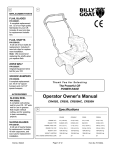
GZ Owner’s Manual
BILLY GOAT GRAZER
Owner's Manual
GZ401H & GZ451S
Accessories
8" HEAVY DUTY
REPLACEMENT
BRUSH
DRIVE BELT
ENGINE
PULLEY
BRUSH DRIVE
PULLEY
OEM quality
replacement wire
brush.
Original
Equipment Belt
for replacement.
Original
Equipment
Pulley
for replacement.
Original
Equipment
Pulley
for replacement.
P/N 600172
P/N 610420
P/N 610417
P/N 610403
Part No 610428
1
Form No F022508A
GZ Owner’s Manual
ABOUT THIS MANUAL
THANK YOU for purchasing a BILLY GOAT ® Grazer. Your new machine has been carefully designed and
manufactured to provide years of reliable and productive service. This manual provides complete operating and
maintenance instructions that will help to maintain your machine in top running order. Read this manual carefully
before assembling, operating, or servicing your equipment.
CONTENTS
SERIAL PLATE DATA AND SPECIFICATIONS
3
4-5
GENERAL SAFETY
INSTRUCTION LABELS
6
PACKING CHECKLIST & ASSEMBLY
7
OPERATION
8-9
MAINTENANCE
10
TROUBLESHOOTING AND WARRANTY PROCEDURE
11
ILLUSTRATED PARTS & PARTS LISTS
12-13
MAINTENANCE RECORD
Part No 610428
14
2
Form No F022508A
GZ Owner’s Manual
SERIAL PLATE DATA
Record the model number, serial number, date of
purchase, and where purchased.
Purchase Date:
Purchased From:
Specifications
GZ401H
Engine: HP
4.0 (2.98 kW)
4.5 (3.36 kW)
Engine: Model
GX120T1QA2
EX130D50031
Engine: Type
HONDA OHV
SUBARU OHV
Engine: Fuel Capacity
2.1 qt. (2.0 L)
3.0 qt (2.9 L)
Engine: Oil Capacity
0.63 qt. (0.6 L)
0.63 qt. (0.6 L)
Total Unit Weight:
84# (38.1 Kg)
85# (38.5 kg)
Max. operating slope
Part No 610428
GZ451S
20
3
o
20
o
Form No F022508A
GZ Owner’s Manual
GENERAL SAFETY INSTRUCTIONS and SYMBOLS
The safety symbols shown below are used throughout this manual. You should become familiar with them before
assembling, operating, or servicing this equipment.
This symbol indicates important information that will prevent injury to yourself or others.
This symbol indicates ear protection is recommended when operating this equipment.
This symbol indicates eye protection is recommended when operating this equipment.
This symbol indicates gloves should be worn when servicing this equipment.
This symbol indicates that this manual and the engine manufacturer’s manual should be read
carefully before assembling, operation, or servicing this equipment.
This symbol indicates important information that will prevent damage to your BILLY GOAT
Grazor.
®
This symbol indicates the engine oil level should be checked before operating this
equipment.
Read and make sure you thoroughly understand the following safety precautions before assembling, operating or
servicing this equipment:
READ this manual and the engine manufacturer’s manual carefully before assembling,
operating, or servicing this equipment.
EAR PROTECTION is recommended when operating this equipment.
EYE PROTECTION is recommended when operating this equipment.
BREATHING PROTECTION is recommended when operating this equipment.
EXHAUST from this product contains chemicals known to the State of California to cause
cancer, birth defects or other reproductive harm.
DO NOT operate this equipment on any unimproved forested, brushy, or grass covered land
unless a spark arrester is installed on the muffler as required by Section 4442 of the
California Public Resources Code. The arrester must be maintained in good working order.
Other states may have similar laws. Federal laws apply on federal lands.
DO NOT run engine in an enclosed area. Exhaust gases contain carbon monoxide, an
odorless and possibly fatal poison.
Part No 610428
4
Form No F022508A
GZ Owner’s Manual
DO NOT run this equipment indoors or in any poorly ventilated area. Refueling outdoors is recommended.
DO NOT refuel this equipment while the engine is running. Allow engine to cool for at least two minutes
before refueling.
DO NOT store gasoline near an open flame.
DO NOT remove gas cap while engine is running.
DO NOT start or operate engine if strong odor of gasoline is present.
DO NOT start or operate engine if gasoline is spilled. Move equipment away from spill until gasoline has
completely evaporated.
DO NOT smoke while filling the fuel tank.
DO NOT check for spark with spark plug or spark plug wire removed. Use an approved spark tester.
DO NOT operate engine without a muffler. Inspect muffler periodically and replace if necessary. If equipped
with muffler deflector, inspect deflector periodically and replace if necessary.
DO NOT operate engine with grass, leaves or other combustible material near the muffler.
DO NOT touch muffler, cylinder, or cooling fins when hot. Contact with hot surfaces may cause severe
burns.
DO NOT leave equipment unattended while in operation.
DO NOT park equipment on a steep grade or slope.
DO NOT operate equipment with bystanders in or near the work area.
DO NOT allow children to operate this equipment.
DO NOT operate equipment with guards removed.
DO NOT operate equipment near hot or burning debris or any toxic or explosive materials.
DO NOT operate equipment on slopes greater than specified in Specifications section of this manual.
DO NOT operate barefoot or wearing open sandals. Always wear substantial footwear
DO NOT place hands or feet underneath unit, or near any moving parts.
DO NOT operate the machine while under the influence of alcohol or drugs.
DO NOT brush excessively steep slopes.
DO NOT change the engine governor setting or overspeed the engine.
ALWAYS Stop the brush when crossing gravel drives, walks, or roads.
ALWAYS Shut the engine (motor) oft and wait until the brush comes to complete stop before performing
maintenance.
ALWAYS Use equipment only in daylight or good artificial light.
ALWAYS wear safety goggles or safety glasses with side shields
ALWAYS remove spark plug wire when servicing equipment to prevent accidental starting.
ALWAYS check fuel lines and fittings frequently for cracks or leaks. Replace if necessary.
ALWAYS store fuel in approved safety containers.
WARNING: Important
Remove all rocks, wire, string, etc. that can present a hazard during work prior to starting.
DO identify and mark all fixed objects to be avoided during work such as sprinkler heads, water valves,
limbs, or clothes line anchors, etc.
Part No 610428
5
Form No F022508A
GZ Owner’s Manual
INTENDED USE
INTENDED USE: This machine is designed for cleaning and removing vegetation and debris from cracks in asphalt
pavement.
Do not operate if excessive vibration occurs. If excessive vibration occurs, shut engine off immediately and check
for damaged or worn brush, loose hardware, loose engine or lodged foreign objects. (See trouble shooting section
on page 11).
INSTRUCTION LABELS
®
The labels shown below were installed on your BILLY GOAT Grazer. If any labels are damaged or missing, replace them before operating this
equipment. Item numbers from the Illustrated Parts List and part numbers are provided for convenience in ordering replacement labels. The
correct position for each label may be determined by referring to the Figure and Item numbers shown.
LABEL WARNING GUARDS
ITEM #59 P/N 900327
LABEL EAR EYE BREATHING
ITEM #57 P/N 890254
LABEL EXPLOSIVE FUEL
ITEM # 2 P/N 400268
DANGER FLYING DEBRIS
ITEM #66 P/N 810736
LABEL EXPLOSIVE FUEL
ITEM # 63 P/N 610107
(Honda only)
LABEL READ MANUAL
ITEM #58 P/N 890301
LABEL DANGER
ITEM #5 P/N 600117
ENGINE LABELS
SUBARU
HONDA
IMPORTANT ENGINE INFORMATION
EM
ENGINE FAMILY - 2FJXS, 1691GA DISPLACEMENT 169CM3
REFER TO OWNER'S MANUAL FOR MAINTENANCE SPECFICATIONS
AND ADJUSTMENTS. THIS ENGINE CONFORMS TO U.S. EPA PH1 AND 2002 CALIFORNIA
EMISSION REGULATIONS FOR SMALL
OFF-ROAD ENGINES.
FUJI HEAVY INDUSTRIES LTD.
THROTTLE CONTROLS
Subaru
Throttle
Honda
Throttle
Choke
Choke
Fuel valve
Part No 610428
Fuel valve
6
Form No F022508A
GZ Owner’s Manual
PACKING CHECKLIST
Your Billy Goat is shipped from the factory in one carton, completely assembled except for the upper handle
assembly, lower handles, handle brace, brush lift rod, and brush.
READ all safety instructions before assembling unit.
TAKE CAUTION when removing the unit from the box.
PUT OIL IN ENGINE BEFORE STARTING
PARTS BAG &
LITERATURE ASSY
Warranty card P/N- 400972, Owner’s Manual P/N-610428.
Parts Bag Checklist
Boxing Parts
Checklist
Safety Glasses
610129 qty. 1
Handle upper
assembly 610438
Handle Brace
610442
Brush Lift Rod
610426
Handle Lower RH
610423
Handle Lower LH
610424
Brush 8” Wire
600172
12
Owner’s Manual
GZ 610428
Engine Manual Per
Model
Honda 4.0 HP
Subaru 4.5 HP
ASSEMBLY
All required assembly can be done using two 1/2" combination wrenches.
1. Install the lower handles one on each side of the unit using bolt (Item 45), washer (Item 54) and nut (Item 52). There are two bolts
per lower handle section. NOTE: The lower handle has a left and right hand section. Be sure when installing that each section will
point to the outside of the unit when hardware is secured.
2.Install upper handle assembly by aligning the holes in the upper handle with the holes in the lower handle stubs that are
preassembled on the machine. Secure the handles together using bolt (Item 46), washer (Item 54), and nut (Item 52) on the
operator’s right hand side. Secure using bolt (Item 64), washer (Item 54), and nut (Item 52) on the operator’s left hand side. Use the
same hardware to secure the flat end of the handle brace (Item 42) to the left side of the handle.
3. Secure the bent end of the handle brace (Item 42) to the face of the engine using bolt (Item 47)
4. Install the Brush Lift Rod (Item 38) by placing one end through the hole in the lift control arm mounted on the upper handle and
securing it with a washer (Item 54) and pin (Item 60). Place the other end thought the brush pivot arm and secure in the same way.
NOTE: The pin and washer come pre-installed in the ends of the rod (Item 38). Remove and re-use them for final assembly.
5. Install Brush (Item 6) by removing the Brush Guard (Item 27) and removing the brush mounting Nut (Item 15) and one Washer
(Item 16). Slide the brush on the shaft and reinstall the washer, nut, and brush guard.
Part No 610428
7
Form No F022508A
GZ Owner’s Manual
OPERATION
Like all mechanical tools, reasonable care must be used when operating machine.
Inspect machine work area and machine before operating. Make sure that all operators of this
equipment are trained in general machine use and safety.
PUT OIL IN ENGINE BEFORE STARTING
Do not operate if excessive vibration occurs. If excessive vibration occurs, shut engine off immediately and
check for damaged or worn brush, loose hardware, loose engine or lodged foreign objects. (See trouble
shooting section on page 12).
STARTING
ENGINE: See engine manufacturer’s instructions for type and amount of oil and gasoline used. Engine must be
level when checking and filling oil and gasoline.
FUEL VALVE: Move fuel valve to "ON" position
STOP SWITCH: Located on the engine. "ON" position.
CHOKE: Operated with choke lever on the face of engine.
THROTTLE: Controlled by the throttle lever located on the face of the engine.
IF YOUR UNIT FAILS TO START:
See Troubleshooting on page 11.
HANDLING & TRANSPORTING:
Using two people to lift machine is recommended. Lift holding the handle and front of the frame. Secure
unit in place during transport. Be sure the brush arm is in the up position and locked in place during transport.
Never lift the machine while the engine is running.
OPERATION
1. Do not operate product when barefoot or wearing open sandals. Always wear safety footwear, pants or slacks that
cover your legs.
2. DO NOT use product on graveled surfaces.
3. Never operate this product without good visibility or light.
4. Start the engine carefully. Make certain the brush is raised in the store position, and that the engine stop switch is
set to “on” before attempting to start. Keep hands, feet, clothing and the like well away from cutting member and other
moving parts.
5. Never attempt to make any adjustments while engine is running.
6. Never direct discharge of material toward bystanders nor allow anyone near the area of operation. Use care in
directing discharge to avoid glass enclosures, automobiles and the like.
7. Stay alert for uneven pavement, holes in terrain or other unstable conditions when using this product. Always push
the machine slowly over rough surfaces.
8. Objects struck by the brush can cause injuries. The surface should always be carefully examined and cleared of all
foreign objects prior to operation. See brush safety instructions, page 9.
9. Move brush lever to store position when the product is not in use. Take all possible precautions when leaving the
machine unattended. Disengage attachments and stop the engine.
10. When cleaning, repairing, or inspecting, make certain the brush and all moving parts have stopped, and the engine
is not running. Disconnect the spark plug wire and keep the wire away from the plug so that unintentional starting does
not occur. Keep all guards free from debris build-up.
11. Never operate this product without guards, plates or other protective devices in place.
12. Use only accessories and attachments supplied, or specifically recommended by the manufacturer.
13. Do not operate this product with a damaged or excessively worn brush.
14. CAUTION: Operate this product from a position where guards block the line of sight to the brush.
Part No 610428
8
Form No F022508A
GZ Owner’s Manual
OPERATING HINTS:
A side-to-side sweeping motion is the quickest way to remove surface vegetation from crevices, even if deeper
crevice cleaning is desired.
After removing surface vegetation, the crevice will be more visible for a deeper cleaning.
Power Brush Safety Requirements
Warning – In normal power brushing operations, the material being removed such as burrs, scale, dirt, weld slat, or
other residue, will fly off the brush with considerable force along with brush filaments, which break off due to fatigue.
The Potential of Serious Injury Exists for both the brush operator and others in the work area (possible 50 or more
feet from the brush). To protect against this hazard, wear Safety Goggles or Full Face Shields Worn Over Safety
Glasses With Side Shields, along with Protective Clothing. You must follow all operator and safety instructions, as
well as all common safety practices, which reduce the likelihood of physical injury, or reduce its severity.
Summary – Power Brush Safety Requirements
Safety Goggles – Safety goggles or full face shields worn over safety glasses with side shields Must Be Worn by
all Operators and Others in the Area of Power Brush Operations.
Guards – Keep all machine guards in place.
Speeds – Observe all speed restrictions indicated on brushes, containers, labels or printed in pertinent literature.
“MSFS” means Maximum Safe Free Speed (RPM) – spinning free with no work applied. For reasons of safety,
“MSFS” should not be exceeded under any circumstances.
Protective Equipment – Appropriate protective clothing and equipment must be used where there is a possibility of
injury that can be prevented by such clothing or equipment.
Warning! Failure To Observe Safety Precautions May Result In Injury.
Brush usage Recommendations
Pressure – Avoid excessive pressure when using a power brush. Excessive pressure causes over-bending of the
filaments and heat build-up resulting in filament breakage, rapid dulling and reduced brush life. Instead of greater
pressure on a brush, it is suggested that you try: 1) a brush with a more aggressive cutting action (increased wire
size, decreased filament length, change to a different brush type, i.e., knot type instead of crimped wire type), or 2)
higher speed (increased R.P.M., increased brush diameter.)
Important Note: Never exceed the recommended Maximum Safe Free Speed R.P.M. (MSFS) rating of the brush.
SAFETY FIRST
FAILURE TO OBSERVE ANY OF THE REQUIREMENTS SHOWN IN THE SAFETY SECTION WILL CREATE HAZARDS AND CAN CAUSE
INJURY.
Brushing Problems – Do Not Allow unsafe Conditions To Continue. Occasionally, due to worn bearings, a bent
spindle, an unusual application, operator abuse, or inappropriate use, a brush may fail.
A brush which is not received in acceptable condition for trouble-free operation may also fail. Do not use or
continue to use a failed brush or one which is functioning improperly (i.e., throwing filaments, out-of-balance, etc.)
as this increases the possibility for further brush failure and hazard of injury. The cause of the failure should be
evaluated and corrected.
This information is based on the collective experience of the ABMA Industrial Division members and provided
solely as a public service for the guidance of the users of the members’ products. These recommendations are not
necessarily complete with respect to any particular application and common sense safety considerations should be
adhered to generally. Any applicable federal, state, local law or regulation must be strictly adhered to, and is
controlling over any recommendation contained herein.
SAFETY INSTRUCTIONS
TWISTED-IN-WIRE BRUSHES
The Twisted-In-Wire brushes, used under power, shall be securely held in a collet, chuck or similar holding device.
Part No 610428
9
Form No F022508A
GZ Owner’s Manual
MAINTENANCE
PERIODIC MAINTENANCE
Periodic maintenance should be performed at the following intervals:
Maintenance Operation
Every Use (daily)
Every 25 Hours
z
Inspect for loose, worn or damaged parts.
Check for excessive vibration.
Every 5 hrs or (daily)
z
z
Inspect belt for wear.
Engine (See Engine Manual)
Lubricate front wheels and rear wheels.
z
Grease brush arm mechanism.
z
CHANGING BRUSH
1. Wait for engine to cool and disconnect spark plug.
2. Remove the brush guard (item 27) by removing the two screws (item 45) that secure it in place. Use gloves and
a shop rag to hold the brush and prevent it from rotating.
3. Using a 3/4" wrench remove brush nut (item 15), and slide brush washer (item 16) off the bearing shaft.
4. Slide the brush (item 6) sideways off of the bearing shaft.
5. Install new brush over the shaft. NOTE: Be sure that to use the nylon bushing that comes with the Billy Goat
replacement brush to insure proper fit between the brush and the shaft.
6. Replace the brush washer (item 16), and the brush nut (item 15). Use a 3/4" wrench to torque the nut to 45 ft.lbs
to secure the brush in place. Be sure to wear gloves and use a shop rag to hold the brush while tightening.
Reinstall the brush guard that was removed in step 2.
CHANGING BELT
1. Wait for engine to cool and disconnect spark plug.
2. Using two 1/2" wrenches, remove the bolt (item 45) and nut (item 52), one on each side, that secures the brush
guard (item 27) and the front pulley guard (item 31). Set the two guards aside.
3. Using a 3/8" wrench, remove the three bolts (item 4) that secure the rear pulley guard in place. Set the guard
aside.
4. Slide the belt off the engine pulley and over the end of the crankshaft, and discard the old belt.
5. Install the new belt in the reverse order of removal.
6. Replace the guards and secure in place with using the hardware you removed.
NOTE: Use only factory original belts for maximum service life. BGI #610420 Inspect the pulleys when replacing the
belt and replace if worn or damaged.
CHANGING PULLEYS
NOTE: Pulleys should be replaced in pairs and not individually to obtain the maximum service life from you unit.
1. Wait for engine to cool and disconnect spark plug.
2. Remove the belt by following the Belt Replacement procedure on the preceding page.
3. Using a 5/32" allen wrench loosen the set screws, two per pulley that secure the pulleys in place.
4. Slide the pulleys off the shafts and slide the new pulleys in place.
5. Use a long straight edge to align the pulleys before tightening the setscrews in place.
6. Torque the setscrews to 15 ft.lbs to secure them.
7. Replace the belt and all guard by referring to the Belt Replacement procedure on the preceding page.
NOTE: Use only factory original pulleys as replacement parts. Inspect the belt when replacing the pulleys and
replace if worn or damaged.
TIRE AIR PRESSURE
Check at regular intervals and maintain.
Rear Tires - 24 Psi (17 kPa).
Part No 610428
10
Form No F022508A
GZ Owner’s Manual
Troubleshooting
Problem
Engine will not start.
Possible Cause
Stop switch of. Throttle in off position. Engine
not in full choke position. Out of gasoline. Bad
or old gasoline. Spark plug wire disconnected.
Dirty air cleaner.
Solution
Check stop switches, throttle, choke
position and gasoline. Connect spark
plug wire. Clean or replace air cleaner.
Or contact a qualified service person.
Abnormal vibration.
Loose or out of balance brush or loose engine. Replace brush. Check engine hardware.
Brush Stalls
W orn belt or pulleys or both
Replace belt and or pulleys
Belt comes off
Pulleys not aligned. Bent belt guard
Align pulleys. Replace bent guards.
Engine is locked, will not
pull over.
Engine Problem
Contact and engine servicing dealer for
engine problems.
When servicing engine refer to specific manufacturers engine owner's manual. All engine warranty is covered by the
specific engine manufacturer. If your engine requires warranty or other repair work contact your local servicing
engine dealer. When contacting a dealer for service it is a good idea to have your engine model number available
for reference (See table page 3). If you cannot locate a servicing dealer in your area you can contact the
manufacturers national service organization.
To reach:
Subaru (Robin America): 800-277-6246 www.robinamerica.com
American Honda: 800-426-7701 www.honda-engines.com
WARRANTY CLAIM PROCEDURE
Should a BILLY GOAT ® machine fail due to a defect in material and/or workmanship, the owner should make a warranty claim
as follows:
•
The machine must be taken to the dealer from whom it was purchased or to an authorized Servicing BILLY GOAT
Dealer.
•
The owner must present the remaining half of the Warranty Registration Card, or, if this is not available, the invoice or
receipt.
•
The Warranty Claim will be completed by the authorized BILLY GOAT Dealer and submitted to their respective BILLY
GOAT Distributor for their territory Attention: Service Manager. Any parts replaced under warranty must be tagged and
retained for 90 days. The model number and serial number of the unit must be stated in the Warranty Claim.
•
The distributor service manager will sign off on the claim and submit it to BILLY GOAT for consideration.
•
The Technical Service Department at BILLY GOAT will study the claim and may request parts to be returned for
examination. BILLY GOAT will notify their conclusions to the distributor service manager from whom the claim was
received.
•
The decision by the Technical Service Department at BILLY GOAT to approve or reject a Warranty Claim is final and
binding.
For online product registration go to www.billygoat.com
Part No 610428
11
Form No F022508A
GZ Owner’s Manual
PARTS DRAWING GZ
Part No 610428
12
Form No F022508A
GZ Owner’s Manual
PARTS LIST
item
no.
1
2
3
4
5
6
7
8
9
10
11
12
13
14
15
16
17
18
19
20
21
22
23
24
25
26
27
28
29
30
31
32
33
34
35
36
37
38
39
40
41
42
43
44
45
46
47
48
49
50
51
52
53
54
55
56
57
58
59
60
61
62
63
64
65
66
67
Part No 610428
PARTS
LIST
Bushing Pivot Frame
Label Hot Engine
Grip Handle 1" X 13"
Screw Self Tap 1/4-20 X 5/8 Type F
Label Danger
Brush 8" Wire Heavy Duty
Caster 5" Dia. X 2"
Wheel 8" x 2.25" w/ 0.625 Bearing
Engine 4.0 HP Honda GX120K1QA2
Engine 4.5 HP Subaru EX13
Label Grazor
Label Height Adjust GZ
Glasses Safety
Axle Grazor
GZ401H
Part No.
360183
400268
400570
890359
600117
600172
610101
610375
610105
610106
610113
610129
610131
QTY
Nut Jam 1/2-20 w/Lock
Washer 1/2" X 2"
Pin Roll 1/4" X 1 3/4"
Nut Lock 1/2-13 Thin Ht.
Pin Screw
Washer Fibre
Fitting Grease
Mandrel GZ W/ BEARING
Arm Pivot WA GZ
Pulley 3" OD X 5/8" Bore
Spring Brush Arm
Guard Rear Pulley
Guard Brush WA GZ
Plate Dirt Deflector
Flap Rubber Dirt Deflector
Pulley 3.25" OD X 3/4" Bore
Guard Belt Brush WA
Belt Gates #6831
Base Engine WA GZ
Handle Upper GZ
Handle Lower RH GZ
Handle Lower LH GZ
Plate Quad GZ
Rod Lift Arm GZ
Arm Lift GZ
Spring Lever GZ
Plate Height Adjust Mount
Brace Handle GZ
Screwcap 5/16-18 X 3/4"
Screwcap 5/16-18 X 1"
Screwcap 5/16-18 X 1 1/2"
Screwcap 5/16-18 X 1 3/4"
Screwcap 5/16-24 X 5/8"
Screwcap #10-24 X 5/8"
Screw Set 5/16-18 X 5/16"
Spacer 5/8" X 2 1/4"
Nut Lock #10-24 Lt. Hex
Nut Lock 5/16-18
Nut Lock 5/8-11
Washer 5/16" Flat
Washer 5/16" SAE
Grip Lever Lift
Label Ear Eye Breathing
Label Read Manual
Label Danger
Pin Hair 1/4"
Washer Flat 1.75 OD X 1.06 ID X 0.100
Key 3/16" X 1"
Key Woodruff 3/16 X 3/4
Screwcap 5/16-18 X 2"
Label GZ decal
Label Danger Flying Debris
Washer 1/4 Flat ZP
610305
610308-P
610319
8161044
610347
610348
610363
610370
610402
610403
610404
610405
610406
610413
610414
610417
610418
610420
610421
610422
610423
610424
610425
610426
610427
610429
610431
610442
8041026
8041028
8041030
8041031
8042026
8059135
8084106
350130
8164005
8160002
8160007
8171003
8172008
850191
890254
890301
900327
900471
9172021
9201078
850234
8041032
610144
810736
8171002
13
QTY
2
1
2
5
1
1
1
2
1
1
1
1
1
GZ451S
Part No.
360183
400268
400570
890359
600117
600172
610101
610375
610437
610106
610113
610129
610131
1
2
1
2
1
1
1
1
1
1
1
1
1
1
1
1
1
1
1
1
1
1
1
1
1
1
1
1
2
6
9
6
1
3
4
2
3
28
1
23
4
1
1
1
1
2
1
1
1
1
1
1
10
610305
610308-P
610319
8161044
610347
610348
610363
610370
610402
610403
610404
610405
610406
610413
610414
610417
610418
610420
610421
610422
610423
610424
610425
610426
610427
610429
610431
610442
8041026
8041028
8041030
8041031
8042026
8059135
8084106
350130
8164005
8160002
8160007
8171003
8172008
850191
890254
890301
900327
900471
9172021
9201078
850234
8041032
610144
810736
8171002
1
2
1
2
1
1
1
1
1
1
1
1
1
1
1
1
1
1
1
1
1
1
1
1
1
1
1
1
2
6
9
6
1
3
4
2
3
28
1
23
4
1
1
1
1
2
1
1
1
1
1
1
10
2
1
2
5
1
1
1
2
1
1
1
1
1
Form No F022508A
GZ Owner’s Manual
MAINTENANCE RECORD
Date
Part No 610428
Service Performed
14
Form No F022508A
GZ Owner’s Manual
BRUSH CUTTER
FORCE BLOWER
AERATOR
If you liked this product please feel
free to view our full line of quality lawn
care, renovation, and debris removal
products at www.billygoat.com
DL VACUUM
Part No 610428
MULTI VACUUM
15
POWER RAKE
Form No F022508A
GZ Owner’s Manual
Part No 610428
16
Form No F022508A