1
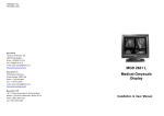
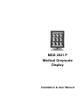
MGD 2621 P
Medical Greyscale
Display
Installation & User Manual
Warning
This is a Class A product. In a domestic environment this product may cause
radio interference in which case the user may be required to take adequate
measures.
© 2001 BARCO nv. Allrights reserved.
SAFETY INSTRUCTIONS
• Read the safety and
operating instructions before
operating the apparatus.
• Retain safety and operating
instructions for future
reference.
• Adhere to all warnings on
the apparatus and in the
operating
instructions
manual.
• Follow all instructions for
operation and use.
•This apparatus conforms to:
IEC601-1,
UL2601-1,
cUL2601-1, EN 60601-1
• This apparatus is classified
as Type B without Applied
Part.
• Class I equipment
• Equipment not suitable for
use in the presence of a
flammable anaesthetic
mixture with air or with
oxygen or nitrous oxyde.
• FCC notice
This equipment has been
tested and found to comply
with the limits of a class A
digital device, pursuant to
Part 15 of the FCC rules.
These limits are designed to
provide
reasonable
protection against harmful
interference when the
equipment is operated in a
commercial environment.
This equipment generates,
uses and can radiate radio
frequency energy and, if not
installed and used in
accordance with the
instruction manual, may
cause harmful interference
to radio communications.
Operation of this equipment
in a residential area is likely
to
cause
harmful
interference in which case
the user will be required to
correct the interference at
his own expense.
Power connection
• Power cord: Utilise a ULlisted detachable power
cord, 3-wire, type SJ or
equivalent, 18 AWG min.,
rated 300 V min., provided
with a hospital-grade type
plug 5-15P configuration for
120V application, or 6-15P
for 240V application.
• Warning: This apparatus
must be earthed!
• Power requirements:
connect the apparatus to an
AC voltage as indicated at
its back. Using a lower
voltage, the apparatus will
not be able to operate. Using
a higher voltage may
damage the apparatus.
If you are not sure of the type
of power supplied, consult
the power company.
• Do not overload wall outlets
and extension cords as this
may result in fire or electric
shock.
• Mains lead protection (U.S.:
Power cord): Supply cords
should be routed so that they
are not likely to be walked
upon or pinched by items
placed upon or against them,
paying particular attention to
cords at plugs and
receptacles.
Water and moisture
• Never expose the
apparatus to rain or moisture.
• Never use the apparatus
near water - e.g. near a
bathtub,
washbasin,
swimming pool, kitchen sink,
laundry tub or in a wet
basement.
Ventilation
• Do not cover or block the
ventilation openings in the
cover of the set. When
installing the apparatus in a
cupboard or another closed
location, heed the necessary
space between the set and
the sides of the cupboard.
Installation
• Place the apparatus on a
flat, solid and stable surface
that can bear the weight of at
least 3 monitors. If you use
an unstable cart or stand,
the set may fall, causing
serious injury to a child or
adult, and serious damage
to the equipment.
MGD 2621 P User's Guide 3
CONTENTS
Introduction ........................................................................................................ 5
Overview ...................................................................................................... 5
About the manuals ....................................................................................... 6
Installation .......................................................................................................... 7
Precautions .................................................................................................. 7
The package contents ................................................................................. 7
Unpacking the display ................................................................................. 8
Power connection ........................................................................................ 8
Location of controls and connectors ............................................................ 9
Connection of video signals ...................................................................... 10
Connection of data signals ........................................................................ 11
Connection of an optical sensor ................................................................ 11
Important considerations ........................................................................... 12
Operation: User controls .................................................................................. 13
How to switch on the display ..................................................................... 13
How to use the automatic power saving system ....................................... 13
How to control contrast and brightness ..................................................... 13
Advised setting for contrast and brightness .............................................. 14
How to use LUC ......................................................................................... 14
Advanced Adjustments (For service staff only) ................................................ 15
The MediCal software ................................................................................ 15
The on-screen menu system ..................................................................... 15
A word about the memory system ............................................................. 16
Focus ........................................................................................................ 17
Geometry ................................................................................................... 17
Info
........................................................................................................ 18
Luma equalizing ........................................................................................ 19
Miscellaneous ............................................................................................ 19
Light
........................................................................................................ 19
Mode selection .......................................................................................... 20
Menu exit ................................................................................................... 20
Maintenance .................................................................................................... 21
Troubleshooting ............................................................................................... 22
Appendix A: Background information ............................................................... 23
Appendix B: Technical specifications ............................................................... 25
MGD 2621 P User's Guide 4
INTRODUCTION
Overview
Resolution and
bandwidths
The BARCO MGD 2621 P is a high-resolution
greyscale portrait display. Its outstanding visual
performance, combining a 2 MegaPixel resolution
with a very high brightness, makes it ideal for
medical imaging and many other medical and
scientific applications.
The MGD 2621 P is compatible with any AC
power system worldwide and automatically
synchronises to a wide range of sync
frequencies. Its high-speed video amplifier
supports pixel clocks up to 250 MHz.
The memory system
The internal memory system can contain the
adjustments for 4 different scanning formats, the
so-called scanning modes. Each scanning format
is characterized by its sync signals. The display’s
internal micro controller continuously samples the
connected sync signals and compares them to
the scanning modes already stored in the
memory. If the connected signal has already been
stored, the micro controller adapts the image to
the corresponding adjustment values in the memory, and further adjustments are unnecessary.
Image conformity and
consistency
Image conformity and consistency are the
keywords. In our factory, the MGD 2621 P
displays are perfectly adjusted and calibrated
before they are shipped to the customer. Internal
circuits, like the TrueGrey® and Automatic White
Stability (AWS) systems, ensure display
consistency over time.
Conformity with the original image quality is
guaranteed by the automatic calibration, which
can be done by means of an optical sensor,
connected to the Sensor connector on the
display. The sensor is not supplied with the
display.
Introduction
5
Calibration and
adjustments
The conformity calibration, as well as the
complete adjustment of the display, can be
performed by means of the remote, user-friendly
MediCal® software package. MediCal, which runs
under Microsoft Windows NT, is especially
developed to adjust and check BARCO’s medical
displays.
A lot of adjustments can also be done on the
monitor itself, by means of an extensive onscreen menu system, accessible from the rear
panel controls.
Power saving system
The MGD 2621 P is equipped with a power
saving system.
When left idle for a certain time, the computer,
connected to the display, will power down the
display in several steps. The power saving
system can be switched on or off during the
installation or adjustment of the display.
This system requires a computer imaging board
that supports power saving management.
Important: It is absolutely necessary that the
impedances of imaging board and display are the
same. If not, the image quality will be inferior.
The MediCal software and the X-Rite DTP92
sensor are not delivered with the display.
MediCal can be ordered separately.
About the manuals
This guide is meant for people who want to install
and use the MGD 2621 P display, as well as
people who need to install and adjust the display.
Chapter 4, Adjustments, is meant for this second
category only, because it describes actions and
procedures that require a technical skill to be
performed properly.
The use of the software MediCal is described in
the MediCal User’s Manual.
Introduction
6
INSTALLATION
Precautions
The package
contents
•
Keep your original packaging. It is designed
for this display and is the ideal protection
during transport.
•
Do not lift the display all by yourself to avoid
injury.
•
Avoid reflections in the picture tube to reduce
eye strain.
•
Place the display on a strong and stable table
or desk if used as desktop display.
•
Keep the display away from heat sources and
provide enough ventilation in case it is built in
a rack or console.
•
Keep the display away from strong sources of
magnetic fields.
•
Make sure the display and computer are both
switched off before connecting the signals.
•
The MGD 2621 P display
•
The accessory box (in which you found this
manual)
Notes:
•
The MGD 2621 P can be part of a complete
MeDis® system, consisting of the display
itself, an imaging board and software. In that
case, the package contains a lot more items.
The contents of the package is then described
in the manual of the complete system.
•
The ambient light shield inside the
accessory box should always be used during
conformity calibration with the X-Rite DTP92
optical sensor.
Installation
7
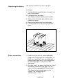
Unpacking the display
The display is packed in a box on a pallet.
To unpack:
1. Cut the ribbons around the box by means of a
pair of wire-cutters.
2. Lift the box from the pallet.
The display remains standing on the pallet.
3. Remove the Accessory box and the upper
polystyrene piece.
4. Remove the plastic bag from the display.
5. Lift the display out of the lower polystyrene
piece.
Power connection
1. Power cord: Utilise a UL-listed detachable
power cord, 3-wire, type SJ or equivalent, 18
AWG min., rated 300 V min., provided with a
hospital-grade type plug 5-15P configuration
for 120V application, or 6-15P for 240V
application.
2. Plug one end of the power cord into the rear of
the display (connector LINE {9}). Plug the
other end into a grounded AC power outlet.
The display automatically adapts to the
voltage. The voltage range is:
100-240 VAC +/- 10%.
Installation
8
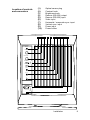
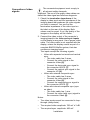
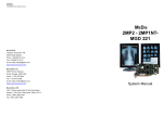
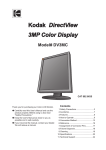
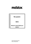
Location of controls
and connectors
{1}
{2}
{3}
{4}
{5}
{6}
{7}
{8}
{9}
{10}
1
2
Optical sensor plug
Contrast knob
Brightness knob
Remote (RS-232) output
Remote (RS-232) input
Video input
Horizontal / composite sync. input
Vertical sync. input
Power input
Power button
3
4
5
6
7
8
9
10
SENSOR
CONTRAST
BRIGHTNESS
REMOTE OUT
REMOTE IN
VIDEO
HS / CS
VS
Installation
9
Connection of video
signals
The connected equipment must comply to
all relevant safety demands.
Important: The use of low-quality video cables can
distort the video signal and influence diagnosis.
1. Check the termination impedance of the
display’s video input and the impedance of the
imaging board that produces the video signals
you want to connect. You can find the
termination impedance of the video input on
the label on the rear of the display. Both
values must be equal. If not, the quality of the
images on the display will be inferior.
2. Connect the video output of the computer’s
imaging board to the video and sync inputs
on the display’s rear panel. Use a proper video
cable. The video cable is not supplied with the
display, unless the display comes as part of a
complete BARCO MeDis system, that also
contains an imaging board.
The inputs accept the following signals:
•
•
•
Video with separate horizontal and vertical
sync.
- The video cable has 3 wires.
- Connect the video signal to the
connector Video {6}.
- Connect the horizontal sync signal to
the connector HS/CS {7}.
- Connect the vertical sync signal to the
connector VS {8}.
Video with external composite sync.
- The video cable has 2 wires.
- Connect the video signal to the
connector Video {6}.
- Connect the composite sync signal to
the connector HS/CS {7}.
Video with internal composite sync (sync
on video).
- The video cable has 1 wire.
- Connect the video (with sync) signal to
the connector Video {6}.
Notes:
•
The video inputs cannot be connected in loopthrough (daisy-chain).
•
The required video amplitude: 700 mV ± 3 dB.
•
The required sync. amplitude: 400 mV.
Installation
10
Connection of data
signals
The display can be controlled remotely by a
computer through the serial data bus. A typical
example of this, is the MediCal software that
controls the display. MediCal runs on a PC that is
connected through the serial data bus. This PC is
not necessarily the same computer as the one
that produces the video signals.
Unlike the video signals, it is possible to daisychain the serial data bus. This means you can
control different displays from one PC.
To connect the data signals:
1. Connect one end of the serial data cable to
one of the PC’s COM ports. If the COM port
has a 25-pin connector, you will need to use a
D25-to-D9 interface connector. The cable
and the interface connector are both supplied
with MediCal.
2. Connect the other end of the serial data cable
to the Remote In connector {5} on the
display’s rear panel.
3. For a daisy-chain application, connect the
Remote Out connector {4} of the first display
to the Remote In connector {5} of the next
display.
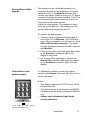
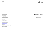
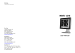
Connection of an
optical sensor
To calibrate the display, connect the optical
sensor to the Sensor connector {1} at the front or
on the rear panel.
Notes:
•
The display supports the DTP 92 from X-Rite
as optical sensor.
•
The optical sensor is not supplied by BARCO.
•
Calibration can be done by means of MediCal
only.
•
Always use the Ambient Light Shield
during calibration.
1
At the front, the sensor plug is
located under the bezel.
Installation
11
Important considerations
•
The best environment for diagnostic
imaging is one with controlled and
dimmed ambient light. The human eye's
sensitivity depends on the ambient light
strength. It is most sensitive to small
contrast changes (or subtle image
details) at limited ambient light levels.
•
The best ambient light level, expressed
in Lux, depends on the application. An
office illumination typically requires 500
Lux. A dimmed environment, like a
softcopy room, requires less than 100
Lux.
•
Using your display in a controlled and
dimmed environment also extends its
lifetime, because the display can
operate at limited brightness and
contrast. These levels correspond to the
calibrated position in most cases.
•
A controlled ambient light environment
implies the ambient light is as constant
as possible. Cover windows to keep out
the daylight. Avoid switching the lights
and viewing boxes on and off. A
consistent environment results in more
image consistency and less eye fatigue.
•
Avoid reflections in the picture tube.
Provide indirect lighting. Don't place the
displays in front of or close to a light
source like a window or viewing box,
although this may be very tempting. As
a rule of thumb, keep viewing boxes at
least one metre (3 feet) away from the
displays.
Installation
12
OPERATION: USER CONTROLS
How to switch on the
display
Press the Power button {10} on the rear panel to
switch on the display.
Note: The display can be switched off by the
automatic power saving system. This is indicated
by the green LED. The LED is ON when the
display is in stand-by.
How to use the
automatic power
saving system
The power saving system, if switched on, can
power down the display when you don't use the
computer that produces the video and sync.
signals for a while. In that way, the system
reduces the display's power consumption. While
the display is powered down, the picture tube will
be blanked, and the green LED on the front is on.
The power saving system is switched off when
the display is produced. It can be switched on by
a qualified technician.
Note: The power saving system can only work if
the connected imaging board supports power
management.
For more details, please read Appendix A,
"Background information".
How to control
contrast and
brightness
The contrast knob {2} and the brightness knob
{3} are located on the rear panel.
When you turn one of the knobs, the on-screen
display (OSD) appears.
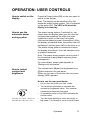
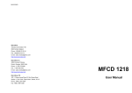
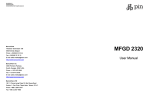
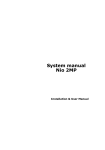
How to use the rear panel knobs
Turning the knob clockwise
increases the value (rear view)
•
As you turn the knob, you feel ‘clicks’.
•
Turn the knob clockwise to increase the
contrast or brightness value. Turn counterclockwise to decrease the value.
•
A moveable cursor in the OSD indicates the
current value.
•
Turn the knob quickly to move the cursor in
big steps. Turn slowly to move in small steps.
Operation
13
Note: When you change the contrast (brightness)
control one step at the time (click per click), the
picture contrast (brightness) will change although
the cursor on the OSD does not move. This is
because contrast (brightness) can be adjusted in
more than 4000 steps, and the OSD is only 6
inches wide.
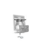
Advised setting for
contrast and
brightness
A fixed vertical dash in the OSD indicates the
calibrated value. This is the advised display
setting for optimum image performance and
consistency in a controlled ambient light
environment.
When you select the calibrated position, the
word CAL appears in the OSD.
Cursor
CAL-indication
How to use LUC
Luminance Uniformity Correction (LUC) is a
system that matches the luminance at the edge
of the picture tube to the luminance in the center.
As a result, the overall luminance is more
uniform.
LUC is switched on when the display is produced.
It can be switched off by a qualified technician.
For more details, please read Appendix A,
"Background information".
Operation
14
ADVANCED ADJUSTMENTS
(FOR SERVICE STAFF ONLY)
The MediCal software
The display is actually designed to be adjusted by
means of MediCal. MediCal provides a very userfriendly way to control and adjust the display.
Even more, you need MediCal to automatically
calibrate the display.
The on-screen menu
system
Especially for circumstances where MediCal is
not available, an extended on-screen menu
system is provided. Only qualified service
personnel should use it!
There are 7 menus. Each menu contains several
items.
To display the on-screen menus:
Turn the Contrast and Brightness knobs on the
rear panel simultaneously. The first menu item
appears.
To navigate through the menu system:
1 Turn the Contrast knob to select another
menu.
Turn clockwise to step forward through the
different menus. Turn counter-clockwise to
step backward.
2 Turn the Brightness knob ONCE (in either
sense) to enter the selected menu. The first
item of the menu appears.
3 Turn the Contrast knob (in either sense) to
select another item. You can only step forward
in a menu.
4 Turn the Brightness knob to adjust the
selected item.
Turn clockwise to increase the value. Turn
counter-clockwise to decrease the value.
5 After you have adjusted an item, turn the
Contrast knob to select the next item or the
next menu.
Advanced Adjustments
15
To exit the menu system:
1 Turn the Contrast knob until the Save
Changes dialog appears in the OSD:
2 Turn the Brightness knob to toggle between
Yes and No. Select Yes to save the changes,
select No to exit without saving the changes.
3 Turn the Contrast knob to exit.
See also: Menu Exit, later in this chapter.
A word about the
memory system
As explained in the introduction of this manual,
the memory of the display can hold four different
scanning formats. Each scanning format is
characterized by the following parameters:
Horizontal sync. frequency, horizontal sync.
polarity, vertical sync. frequency, and vertical
sync. polarity.
If the parameters of the connected signal are the
same of the parameters of one of the scanning
formats in memory, the automatic scanning
system selects this scanning mode. This means
the image on the display adapts to all the
adjustment values stored in this scanning mode.
In case the connected sync signal doesn't match
one of the stored scanning modes, the automatic
scanning system selects the nearest scanning
mode. This means the scanning mode of which
the stored sync frequencies are as close as
possible to the sync frequencies of the connected
signal.
When you change one or more adjustment
values, and you decide to save the changes upon
exit of the menu system, the changed values are
stored in the actually selected scanning mode.
This means the actually selected scanning
mode is overwritten by the new adjustment
values.
Advanced Adjustments
16
Focus
1 Turn the Brightness knob once to enter the
Focus menu. The first focus adjustment
appears: Static Focus.
2 Turn the Brightness knob to adjust static
focus.
Static focus has effect on the complete
screen.
3 Turn the Contrast knob to switch to the next
focus adjustment. This is the first of 9 zonedependent focus adjustments.
4 Turn the Brightness knob to adjust the focus
in the selected zone.
5 Turn the Contrast knob to select the next
zone.
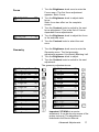
Geometry
1 Turn the Brightness knob once to enter the
Geometry menu. The first geometry
adjustment appears: H(orizontal) Blanking Left.
2 Turn the Brightness knob to adjust.
3 Turn the Contrast knob to switch to the next
adjustment.
The geometry adjustments are:
Important: VP Width is a service
adjustment. It can be done by means of the
proper tools only. The adjustment is
described in the Service Manual.
Advanced Adjustments
17
If your display is equipped with the Southern
Hemisphere option, the on-screen display menu
contains additional functions to adjust the image
geometry.
The Southern Hemisphere commands are in the
Geometry menu:
Info
-
SH Compensation On (Off): For proper
geometry adjustment in the Southern
Hemisphere, SH Compensation must be ON.
If not, the SH controls will not function.
-
SH Comp. Top:
-
SH Comp. Bottom:
Turn the Contrast knob to switch to the next
menu.
This is the display type.
This is the display's serial number
This is the display's order number.
The order number of the internal software.
The internal software version.
The total operating time since production.
The currently selected scan mode.
Advanced Adjustments
18
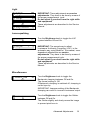
Light
IMPORTANT: These adjustments are service
adjustments. They have to be done by means of
the proper measurement tools.
Do not adjust if you don’t have the right skills
and equipment!
These adjustments are described in the Service
Manual.
Luma equalizing
Turn the Brightness knob to toggle the LUC
system between Off and On.
IMPORTANT: The normal way to adjust
Luminance Uniformity Correction (LUC), is the
automatic way, using MediCal. The manual, zonedependent adjustments are service
adjustments. They have to be done by means of
the proper measurement tools.
Do not adjust if you don’t have the right skills
and equipment!
These adjustments are described in the Service
Manual.
Miscellaneous
Turn the Brightness knob to toggle the
Backporch clamping between Off and On.
The normal setting is: Off.
If Backporch clamping is switched off, clamping is
on the sync tip.
IMPORTANT: Improper setting of the Backporch
clamping can result in incorrect luminance output.
Turn the Brightness knob to toggle the Orbiter
between Off and On.
The Orbiter slightly and slowly moves the image
to prevent pixel burn-in.
Advanced Adjustments
19
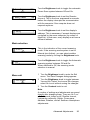
Turn the Brightness knob to toggle the automatic
Power Save system between Off and On.
Turn the Brightness knob to set the Remote
time-out. This is the time, expressed in seconds,
before the display interrupts the communication
with the computer if the computer does not
respond anymore.
Turn the Brightness knob to set the display’s
address. This is necessary if several displays are
controlled by the same computer (by means of
MediCal). In that case, every display must have a
different address.
Mode selection
This is the indication of the current scanning
mode. If the scanning mode system is set to
Manual (see further), you can select another
scanning mode by turning the Brightness knob.
Turn the Brightness knob to toggle the Automatic
scanning system between Off and On.
When switched to Off, the scanning mode
selection is manual.
Menu exit
1 Turn the Brightness knob to enter the Exit
menu. The Save Changes dialog appears.
2 Turn the Brightness knob to toggle between
Yes and No. Select Yes to save the changes,
select No to exit without saving the changes.
3 Turn the Contrast knob to exit.
Note:
A number of settings and adjustments are saved
directly after changing them. They are: ALC on/
off, Backporch clamp on/off, Remote timeout,
Luminance uniformity, Orbiter, Power save,
Address, Rotation, and all Southern Hemisphere
adjustments.
Advanced Adjustments
20
MAINTENANCE
Picture tube
The glass panel of the picture tube is handled
with a special coating. Take care not to damage
or scratch the coating.
Clean the picture tube with a soft woollen or
cotton cloth.
The cloth should be moist, not wet!
Use a watery solution or a mild commercial glass
cleaning solution.
Apply (e.g., spray) the solution on the cloth, not
on the picture tube.
Cabinet
Clean the cabinet using a recognised cleaning
product for medical equipment. The cloth you use
must be moist, not wet!
The cabinet has been tested for resistance to the
following products: Cidex, Betadine, Alcohol
(Isopropyl and Ethyl), Ammonia-based cleaners
(Windex) and Aquasonic Gel.
Maintenance
21
TROUBLESHOOTING
There appears no image on the picture
tube, the green LED on the front is out
•
Check if the power cord is properly connected
to the power outlet and to the display.
•
Check if the power button is depressed.
•
Check if contrast and brightness are not set
to 0.
There appears no image on the picture
tube, the green LED is on
The display is switched in Stand-by by the
automatic Power saving system.
•
Try to switch on the display by pressing any
key on the keyboard of the computer that
produces the video and sync. signals for the
display.
•
Check if both horizontal and vertical sync.
signals are connected to the display and to the
computer.
On the picture tube appears the message
"No Valid Sync Signal"
•
Check if both horizontal and vertical sync.
signals are connected to the display and to the
computer.
•
Check if the sync. signals are connected to
the proper inputs (refer to the chapter
"Installation").
•
Check if both horizontal and vertical sync.
frequencies match the display specifications
(refer to the chapter "Technical
specifications").
For other problems, please consult your technical
service department.
Troubleshooting
22
APPENDIX A:
BACKGROUND INFORMATION
Clamping
Inside the display, the video signal from the video
input is connected to the video amplifier. This
circuit amplifies the signal, paying special
attention to two signal levels: the amplitude and
the dc-level. The dc-level of the video signal in
the video amplifier determines the eventual black
level of the image on the picture tube (CRT).
The circuits of the video amplifier can pick up
interferences from different ambient sources.
These interferences can change the dc-level of
the video signal. In the end, the black level of the
image on the CRT will be incorrect and unstable.
This is avoided by special clamping circuits inside
the video amplifier. They clamp a particular part of
the video signal to a constant dc-voltage. In this
way, the video dc-level and thus the image black
level is kept constant.
In a color display, clamping is normally done on
the backporch. This is the part of the video signal
that follows the sync pulse. But if the video
signal's backporch is too small for clamping,
another part of the signal has to be chosen. In
that case, sync tip clamping has to be selected.
In the MGD 2621 P, clampig is best (and default)
done on the sync tip.
Luminance Uniformity
Correction
A characteristic (or limitation) of every picture
tube (CRT) is that the luminance decreases
towards the edge of the screen surface. The
decrease is normally 20 to 30 %.
This is caused by the shape of the picture tube.
Inside the CRT, a so-called electron gun shoots
an electron beam towards the front (the glass
panel). Because this panel is rather flat instead of
having a spheric shape, the electron beam has to
'travel' a longer distance in the corners than in the
center. So the intensity is higher in the center.
This phenomenon is even increased by the
irregular distribution of the phosphor and
aluminium layer on the glass panel. These tend to
Background information
23
be thicker in the center.
BARCO has developed a special system, called
Luminance Uniformity Correction (LUC), that
solves this problem. The LUC system enhances
the light output at the edges of the CRT, so that
the luminance there is the same as in the center.
The LUC system is calibrated in the factory. From
time to time, it has to be re-calibrated at the
customer's site by means of the light sensor you
use for normal color calibration. The system can
be calibrated and switched on or off by a qualified
technician.
Power saving system
The display is equipped with circuits that can
handle power saving management. When the
system is switched on, it can power down the
display in several steps.
The system is controlled by the imaging board or
the PC that delivers the video signals. When you
are working on the computer, the imaging board
delivers both sync signals, and the display is
operating normally. When you don't touch the
computer keyboard for a certain time, the imaging
board only delivers vertical sync. This is sensed
by the display's micro controller, that blanks the
image on the CRT. This results in a drop of power
consumption with about 30 %.
When you leave the computer idle for a longer
period, the imaging board now delivers horizontal
sync only. As a result, the display's micro
controller switches off a number of internal
circuits. The power consumption has now
dropped with about 35 %.
At last, the imaging board delivers no sync
signals at all, and the micro-controller switches off
all but one power supplies in the display. Only the
micro-controller's own supply keeps on running,
resulting in a very low power consumption of 5 W.
If you start using the computer again, the imaging
board switches on both sync signals, and the
micro-controller switches on the display.
The times after which the different steps of power
management must become active, is set in the
PC's display properties.
Background information
24
APPENDIX B:
TECHNICAL SPECIFICATIONS
Picture tube:
Faceplate transmission: +/- 33%
Faceplate type: ARC panel
Image representation: portrait
Phosphor: P45
Light output:
Calibrated: 300 cd/m²
Peak: 600 cd/m²
Resolution:
Max. adress. pixels: 1280
Max. adress. lines: 1600
Scanning systems
Horizontal scanning:
Multi sync: -controller controlled
Minimum frequency: 80 kHz
Maximum frequency: 130 kHz
Minimum blanking : 2.4 s
Storable scan frequencies: 4
Prealigned scans: 1 + VGA
Vertical scanning:
Minimum frequency: 48 Hz
Maximum frequency: 150 Hz
Minimum blanking: 300 s (after leading
edge)
Geometry
Nominal size (4/3 ratio): 300mm x 400mm
Nominal size (4/5 ratio): 304mm x 380mm
Power supply:
Voltage: 100 - 240 V +/- 10%
Frequency: 50/60 Hz
Current: 2.3 A
Environmental
Temperature range (°C):
Storage:
-20/+65
Operation:
0/+45
Within specs:
15/+30
Altitude: storage: 25 000 ft
operational:
10 000 ft
Humidity (relative): 95 % max., non
condensing
Weight:
Unpacked
approx. 39.8 kg
Packed
approx. 58.3 kg
Dimensions packing:
H x W x D: 788mm x 630mm x 780mm
Dimensions monitor (mm):
Height: 558
Width: 400
Depth: 561
Modifications reserved.
Inputs
Video
BNC connectors
Nominal level: 0.7 Vpp
Sync
BNC connectors
Nominal level: 0.5 Vpp
Communication inputs/outputs
RS232 9-pin sub D connector
Baudrate: 9600
Technical specifications
25
MGD 2621 P User's Guide 26
B410030/Rev. 00
February 2001
BarcoView
Theodoor Sevenslaan 106
8500 Kortrijk, Belgium
Phone: +32(0)56 23 32 44
Fax: +32(0)56 23 33 74
E-mail: [email protected]
http://www.barcoview.com
BarcoView Inc
3059 Premiere Parkway
Duluth, Georgia, 30097,USA
Phone: +1 678 475 8000
Fax: +1 678 475 8100
E-mail: [email protected]
http://www.barcoview.com
Printed in Belgium