1
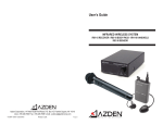
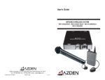
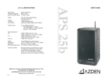
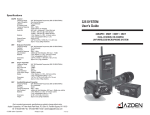
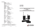
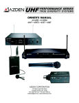
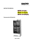
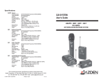
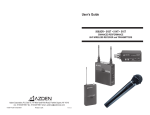
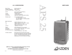
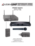
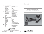
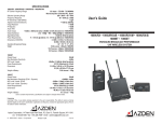
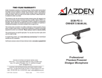
VHF PERFORMANCE SERIES WIRELESS MICROPHONE SYSTEMS OWNERS MANUAL 311DRH 311DR 221R 211R 200R 31LT 31IT 32BT 32IT 31HT 31XT AZDEN CORPORATION 147 New Hyde Park Road Franklin Square, NY 11010 516.328.7500 vox 516.328.7506 fax [email protected] www.azdencorp.com Thank you for purchasing AZDENS PERFORMANCE SERIES wireless system. This manual covers the 311DRH, 311DR, 221R, 211R and 200R receivers and the 32BT (Lavaliere), 31XT (Plug-in XLR), 31HT (Handheld), 31LT (Lavaliere) and 31IT (Instrument) transmitters. Receiver Descriptions The 311DRH True Diversity VHF Half-Rack Receiver: The 311DRH contains two separate receivers, each operating on the same frequency. The incoming signal is constantly monitored by a diversity circuit, which switches automatically to the receiver with the stronger RF signal. This allows wireless performance that is virtually drop-out free, even under the most adverse conditions. The receiver features 1/4-inch as well as XLR output jacks with volume and squelch adjustment. 9 (1) Power LED and On/Off switch. After plugging in the 311DRH depress the On/Off switch to turn unit on and illuminate the Power LED. See #5 for more details. (2) Antenna A-B LEDs. When the transmitter is turned on and is in reception range of the receiver, either the A or B LED will light up GREEN, depending on which receiver circuit is getting the strongest signal from the transmitter. Flickering from the A to B LED is a normal function of the system. (3) Radio Frequency level and Audio level LEDs. The 311DRH has two 5-segment LED displays to show the strength of both the incoming FM carrier and the audio signal level. The receiver will perform best if the RF level is kept between the fourth and fifth LED. Dips to the third LED may happen occasionally and are tolerable. The audio level LEDs will show the incoming audio signal from 26dB to +5dB. The fifth LED is red and will come on if the audio component of the incoming signal is approaching distortion. (1) (4) Antenna connections. On the 311DRH the antennas are connector mounted (BNC) so that the supplied antennas can be disconnected and/or remoted using coax cable if needed. (5) 12-Volt Input. Plug the supplied AC adaptor into the 12-volt input on the receiver and then into a 110-120 VAC electrical outlet. Use only the adaptor supplied (BC-26U) as other adaptors may damage the receiver. (6) Output Adjustment. Rotate this knob clockwise to increase, or counter-clockwise to decrease volume level. (7) Output (unbalanced). Using a suitable audio cable (not supplied), connect the 1/4-inch phone jack end to the audio output on the receiver and connect the other end of the cable to the suitable mic/line input of an audio mixer or amplifier. (8) Output (balanced). Using a suitable audio cable (not supplied) connect the XLR connector to the audio output on the receiver, and connect the other end of the cable to the suitable mic/line input of an audio mixer or amplifier. (9) Rack ears. If you wish to use the 311DRH in a standard 19" rack by itself you can use the HR-1 rack kit and attach the rack ears using the four supplied machine screws (two per side near front) as shown. If you wish to use the 311DRH in a standard 19" rack with another 311DRH or a 411DRH you can use the HR-2 rack kit and attach the rack ears using the four supplied machine screws (on the outer sides of each unit) as shown. Also attach the joining plate (supplied) underneath the two units by screwing in the supplied machine screws We also suggest that you remove the feet from the bottom of the receivers for the proper clearance required in a standard rack. (see diagram.) (10) Squelch adjust. This adjusts the point at which the receiver will shut off or squelch the incoming RF signal when it becomes too weak. Turning the control counter-clockwise raises the threshold, allowing more signal to enter while turning the control clockwise lowers the threshold, letting in less signal. (11) Frequency label Indicates what frequency (in MHz ) the receiver operates on. The AZDEN transmitter in use must also be on the same frequency. (2) The 311DR True Diversity VHF Receiver: The 311DR contains two separate receivers, each operating on the same frequency. The incoming signal is constantly monitored by a diversity circuit, which switches automatically to the receiver with the stronger RF signal. This allows wireless performance that is virtually drop-out free, even under the most adverse conditions. The receiver features a 1/4-inch as well as an XLR output jack and volume adjustment. 8 (1) Power LED When the receiver is plugged in, the Power LED will turn RED. See #4 for more details. (2) Antenna A-B LEDs When the transmitter is turned on and is in reception range of the receiver, either the A or B LED will light up GREEN, depending on which receiver circuit is getting the strongest signal from the transmitter. Flickering from the A to B LED is a normal operation of the system. (3) Antennas Extend the antennas fully vertical for best reception. When not in use, lower the antennas and put them in their holder to avoid damage. (4) 12 Volt Input Plug the supplied AC adaptor into the 12-volt input on the receiver first, then into a 110-120 VAC electrical outlet. Use only the adaptor supplied (BC-26U) as other adaptors may damage the receiver. (5) Output Adjustment Rotate this knob clockwise to increase, or counter-clockwise to decrease volume level. (6) Output (unbalanced) Using a suitable audio cable (not supplied), connect the 1/4-inch phone jack end to the audio output on the receiver, and connect the other end of the cable to the mic/line input of an audio mixer or amplifier. (3) (7) Frequency label Indicates what frequency (in MHz) the receiver operates on. The AZDEN transmitter in use must also be on the same frequency. (8) Output (balanced) Using a suitable audio cable (not supplied) connect the XLR connector to the audio output on the receiver, and connect the other end of the cable to the suitable mic/line input of an audio mixer or amplifier. 221R Two-channel VHF receiver: The 221R contains two VHF receivers operating on different frequencies. This allows single or simultaneous use of two transmitters. The receiver features two 1/4-inch output jacks and two volume adjustments - one for each channel. (1) Power/Receiving LED When the receiver is plugged in, both the A and B Power/Receiving LEDs will turn RED. When one or both of the transmitters is turned on and are within reception range of the receiver the A and/or B Power/Receiving LEDs will turn from RED to GREEN indicating that the transmitter(s) signal is being received. (2) Antennas Extend the antennas fully vertical for best reception. When not in use, lower the antennas and put them in their holders to avoid damage. (3) 12 Volt Input Plug the supplied AC adaptor into the 12-volt input on the receiver then into a 110-120 VAC electrical outlet. Use only the adaptor supplied (BC-26U) as other adaptors may damage the receiver. (4) Output Adjustment Rotate this knob clockwise to increase, or counter-clockwise to decrease the volume level. Please note that the 221R has two output adjustments, one for Ch.A and one for Ch.B (4) (5) Output (unbalanced) Using a suitable audio cable (not supplied), connect the 1/4-inch phone jack end of the audio output on the receiver, and connect the other end of the cable to the mic/line input of an audio mixer or amplifier. Please note that the 221R has two outputs, one for Ch.A and one for Ch.B. (6) Frequency label Indicates what frequencies (in MHz) the receiver operates on. The AZDEN transmitters in use must also be on the same frequency. Please note that the 221R has two frequency labels, one for Ch.A and one for Ch.B. 211R Single channel VHF receiver: The 211R features a 1/4-inch output jack and volume adjustment. (1) Power/Receiving LED When the receiver is plugged in, the Power/Receiving LED will turn RED. When the transmitter is turned on and is in reception range of the receiver the Power/Receiving LED will turn from RED to GREEN indicating that the transmitter signal is being received. (2) Antenna Extend the antenna fully vertical for the best reception. When not in use, lower the antenna and place it into its holder to avoid damage. (3) 12-Volt Input Plug the supplied AC adaptor into the 12-volt input on the receiver and then into a 110-120 VAC electrical outlet. Use only the adaptor supplied (BC-26U) as other adaptors may damage the receiver. (4) Output Adjustment Rotate this knob clockwise to increase, or counter-clockwise to decrease volume level. (5) Output (unbalanced) Using a suitable audio cable (not supplied) connect a 1/4-inch phone jack end to the audio output on the receiver and connect the other end of the cable to the mic/line input of an audio mixer or amplifier. (5) (6) Frequency label Indicates what frequency (in MHz) the receiver operates on. The AZDEN transmitter in use must also be on the same frequency. 200R Single channel VHF receiver: The 200R features a 1/4-inch output jack and volume adjustment. (1) Power/Receiving LED When the receiver is plugged in, and the Power button is press IN, the Receiving LED will turn RED. When the transmitter is turned on and is in reception range of the receiver the Power/Receiving LED will turn from RED to GREEN indicating that the transmitter signal is being received. Press the Power button OUT to turn the 200R off. (2) Antenna Extend the antenna fully vertical for the best reception. When not in use, lower the antenna to avoid damage. (3) 12-Volt Input Plug the supplied AC adaptor into the 12-volt input on the receiver and then into a 110-120 VAC electrical outlet. Use only the adaptor supplied (BC-26U) as other adaptors may damage the receiver. (4) Output Adjustment Rotate this knob clockwise to increase, or counter-clockwise to decrease volume level. (5) Output (unbalanced) Using a suitable audio cable (not supplied) connect a 1/4-inch phone jack end to the audio output on the receiver and connect the other end of the cable to the mic/line input of an audio mixer or amplifier. (6) Frequency label Indicates what frequency (in MHz) the receiver operates on. The AZDEN transmitter in use must also be on the same frequency. (6) TRANSMITTER DESCRIPTIONS Model 32BT: Lavalier microphone with body-pack transmitter. Ideal for speaking applications such as Lecturers, Actors, Actresses, etc. Model 31XT: Plug-in XLR transmitter turns any dynamic metal-bodied microphone with XLR output into a wireless microphone. Model 31HT: Handheld microphone with a built-in transmitter. For all vocal applications such as Vocalists, Karaoke Singers, etc. Model 31LT: Lavalier microphone with body-pack transmitter. Ideal for speaking applications such as Lecturers, Actors, Actresses, etc. Model 31IT: Instrument body-pack transmitter. Designed for electric guitar and bass. 32BT Lavalier Microphone with body-pack transmitter: (1) Open the battery compartment lid by sliding it in the direction indicated and raising it. (2) Insert one fresh Alkaline 9-volt battery into the compartment. Make sure battery polarity is correct. (3) Frequency Label The Frequency label indicates what frequency (in MHz) the transmitter broadcasts on. The AZDEN receiver in use must also be on the same frequency. (7) (4) Audio Input Level Control Turn clockwise to increase, or counter-clockwise to decrease the input level. A small screwdriver is supplied to make adjustments. The level control is factory-preset in the center position. (5) 3 Position Switch The left position: OFF The middle position: STANDBY The right position: ON In the STANDBY position, the audio is muted. (6) LED Indicator Turns red when the switch is in STANDBY position and green in ON position. NOTE: Remove the battery if the transmitter will not be used for a long period of time. (7) Audio Output Connector This 3.5mm mono connector is where the mic is plugged in. This connector was designed to be used with a special screw-down connecting jack that eliminates the possibility of the jack being accidentally pulled out. A standard 3.5mm mono jack can also be used but will not afford the extra protection. (8) Metal Belt Clip Used to attach the 32BT securely to a belt. 31XT Plug-in transmitter adaptor: Note: The 31XT is designed to turn any wired dynamic metal-body microphone that has an XLR output into a wireless microphone. Connecting the 31XT: Disconnect the microphone cable from the microphone by pushing down on the release button where the microphone and cable connect. Connect the 31XT by lining up the pins on the microphone with the holes on the transmitter, and insert. Push the 31XT into the microphone until it locks into place. (8) Removing the 31XT: Push down on the release button and pull out. (1) Turn the bottom half of the case counter-clockwise until it is completely off. (2) Insert one fresh alkaline AA battery into the compartment. Make sure battery polarity is correct. Replace the bottom half of the case and turn clockwise until snug. DO NOT OVERTIGHTEN. (3) Frequency Label: The frequency label indicates what frequency (in MHz) the transmitter broadcasts on. The AZDEN receiver in use must also be on the same frequency. (4) Power Off/On: Switches the transmitter off or on. (5) Audio Off/On: Slide the switch to On for normal operation. Slide it to Off to mute the audio. NOTE: When turning the transmitter on, slide the Power On first, and then slide the Audio to On. When turning the transmitter off, first slide the Audio to Off. (6) LED: Turns RED when the Power is On and the Audio is Off. Turns GREEN when the Power and Audio are On. (7) Level: Turn clockwise to increase, or counter-clockwise to decrease the input level. A small screwdriver is supplied to make adjustments. The level control is factory-preset in the center position. NOTE: Remove the battery if the transmitter will not be used for a long period of time. 31HT Handheld Microphone Transmitter: (1) Turn the bottom half of the microphone case counter-clockwise until it is completely off. (2) Insert one fresh Alkaline AA battery into the compartment. Make sure battery polarity is correct. Then, replace bottom half of microphone case and turn clockwise until snug. DO NOT OVER-TIGHTEN. (9) (3) The frequency label indicates what frequency (in MHz) the transmitter broadcasts on. The AZDEN receiver in use must also be on the same frequency. + - (4) 3 Position Switch The bottom position: OFF The middle position: STANDBY The top position: ON In the STANDBY position, the audio is muted. (5) LED indicator Turns RED when the switch is in STANDBY position and GREEN in ON position. NOTE: Remove the battery if the transmitter will not be used for a long period of time. 31LT Lavalier Microphone with body-pack transmitter: 31IT Instrument body-pack transmitter: (1) Open the battery compartment lid by sliding it down and raising it. (10) (2) Insert one fresh Alkaline 9-volt battery into the compartment. Make sure the battery polarity is correct. (3) Frequency Label The Frequency label indicates what frequency (in MHz) the transmitter broadcasts on. The AZDEN receiver in use must also be on the same frequency. (4) 31IT 1/4-inch plug Plugs into output on electric guitars and keyboards. or (4) 31LT lavalier mic: Clips onto a tie, lapel, etc. The transmitters cable doubles as an antenna. Extend the cable as much as possible for the best performance. (5) Audio Input Level Control Turn clockwise to increase, or counter-clockwise to decrease the input level. A small screwdriver is supplied to make adjustments. The level control is factory-preset in the center position. (6) 3 Position Switch The left position: OFF The middle position: STANDBY The right position: ON In the STANDBY position, the audio is muted. (7) LED Indicator Turns RED when the switch is in STANDBY position and GREEN in ON position. NOTE: Remove the battery if the transmitter will not be used for a long period of time. OPERATING THE SYSTEM Do not place the receiver on a metal surface, and avoid obstructions between the receiver and transmitter, since this could degrade the performance of the equipment. First, make sure that the power to all your components is turned off. Connect an audio cable from the output of (11) the receiver to a mic/line input on your audio mixer or amplifier. Plug the receivers AC adaptor into the 12V input jack on the receiver, and then plug it into the 110-120 VAC electrical outlet. With the volume of your mixer or amplifier set to minimum level, turn your systems power on. Turn on the transmitter(s). Make sure all LEDs on the receiver and transmitter(s) are operating as described in the preceding pages. Now set the receivers volume to the midway point and adjust the volume level on your mixer or amplifier. 32BT, 31LT & 31XT: With someone talking into the microphone, turn the volume on the mixer or amplifier to the desired level. If there is too much, or not enough gain, lower or raise the volume on the receiver. If the sound is distorted, lower the input gain on the transmitter. 31HT: With someone talking or singing into the microphone, turn the volume control on the mixer or amplifier to the desired level. If there is too much, or too little gain, adjust the volume on the receiver. If the sound is distorted, move the microphone further away from the sound source. 31IT: Plug the cable into a guitar or bass. Set the instrument volume to the midway point. While playing the instrument, adjust the volume on the mixer or amplifier to the desired level. If there is too much, or too little gain, adjust the volume on the receiver. If the sound is distorted lover the input gain on the 31IT. With the system now operating, move around the performing area to make sure no problems, such as feedback or RF signal loss occur. NOTES: - Do not use or store the system in areas of high temperature or humidity. - Do not use the system near a broadcast station, airport, or airplanes, as it may cause interference. If you are interfering with other transmissions, you must turn the system off. - These systems contain no user-serviceable parts. If any unauthorized service is performed, it may void the warranty. FCC NOTES: AZDEN 32BT, 31HT, LT, IT, and XT, conform to Parts 74 & 90 of the FCC rules. The receivers conform to part 15 of the FCC rules. You should contact the FCC office near you for the proper filing forms. (12) SPECIFICATIONS OVERALL Frequency Range: VHF 169 -216MHz Working Range: Up to 300 feet Distortion: Less than 1% (15kHz deviation) Frequency Response: 40Hz to 15kHz, 3dB Dynamic Range: Better than 100dB S/N Ratio: Better than 95dB Operating Temperature: 0° 45° C (32° 113° F) Noise Reduction: 2:1 logarithmic compressor/expander Oscillator/Modulation: Crystal Controlled/FM Transmitter Microphone Unit RF Output Power Input Impedance Audio Adj.Range Battery Battery Life Size Weight 31HT Uni Dynamic 10mW (50mW max) 8K ohms N/A AA (1.5V) 62X221mm 2.44X8.7" 213g (7.5oz) 31LT 31IT Omni Electret N/A 30mW (50mW max) 2.2K ohms 100K ohms 30 dB 9V (006P) 8-10 hours (using alkaline battery) 86(H)X60(W)X21.5(D)mm 3.4(H)X2.3(W)X0.84(D)" 112g (4.0oz) 86(H)X60(W)X21.5(D)mm 3.4(H)X2.3(W)X0.84(D)" 152g (5.4oz) Receiver (211R, 221R, 311DR and 311DRH) Receiver type: Super Heterodyne/Crystal Controlled Image Rejection: Better than 60dB Reception Sensitivity: Better than 15dBV Reception Selectivity: 60kHz Audio Output Adj. Range: min. -30dB, center 0dB, max. +6dB Audio Output Impedance: 2.2K ohms unbalanced (200R, 211R, 221R, 311DR, 311DRH) 4.4K ohms balanced (311DR, 311DRH) Power Requirements: 12V DC - 300mA Size: 215(W)x210.4(D)x44(H)mm 8.4x8.4x1.7" (311DRH) 280(W)x120(D)x37(H)mm 11x4.7x1.4" (311DR, 221R) 150(W)x120(D)x27(H)mm 5.9x4.7x1" (211R) 141(W)x129.5(D)x24(H)mm 5.55x5.1x0.95" (200R) Weight: 1.2kg (42.3oz) (311DRH) 830g (29.3oz) (311DR) 875g (30.8oz) (221R) 485g (17.1oz) (211R) 252g (8.9oz) (200R) (13) 31XT N/A 10mW (50mW max) 47K ohms AA (1.5V) 33X120mm 1.3X4.7" 92g (3.2oz) (14)