1
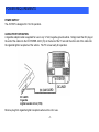
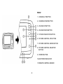
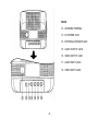
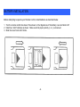
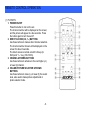
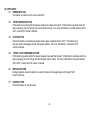
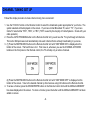
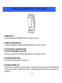
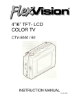
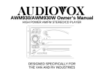
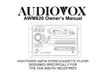
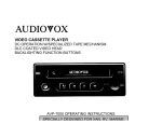
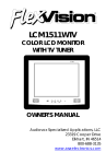
5” COLOR TV/MONITOR
DC OPERATION WITH REMOTE CONTROL
AVT-597 OPERATING INSTRUCTIONS
SPECIALLY DESIGNED FOR THE
VAN AND AUTOMOTIVE INDUSTRIES
RECOMMENDED GUIDELINES FOR THE USE OF A
VIDEO MONITOR/TV IN A MOTOR VEHICLE
• A VIDEO MONITOR/TV is designed for rear seat viewing only. This product may only be installed in the rear
seat compartment of the vehicle, out of the driver’s view.
• Installation in any other area of the vehicle, including anywhere within the driver’s view, is illegal in most states,
provinces and countries and may lead to driver distraction resulting in an accident, injury and or death. If you
are unsure of regulations regarding this, please consult your local laws to determine how this applies to you.
• Users should be aware of the possible noise distraction caused by the use of the product and should carefully
monitor the volume so as not to interfere with the driver’s attention to surrounding traffic conditions.
EXPLANATION OF GRAPHIC SYMBOLS:
CAUTION
RISK OF ELECTRIC SHOCK
DO NOT OPEN
CAUTION: TO REDUCE RISK OF ELECTRIC SHOCK,
DO NOT REMOVE COVER (OR BACK)
NO USER-SERVICABLE PARTS INSIDE
REFER SERVICING TO QUALIFIED SERVICE PERSONNEL
The lightning flash with arrowhead within
a triangle is intended to tell the user that
parts inside the product are a risk of
electric shock to persons.
The exclamation point within a triangle
is intended to tell the user that important
operating and servicing instructions are
in the papers with the appliance.
WARNING: TO PREVENT FIRE OR ELECTRIC SHOCK HAZARD, DO NOT EXPOSE
THIS PRODUCT TO RAIN OR MOISTURE.
IMPORTANT SAFETY INFORMATION
1. Read Instructions – All the safety and operating instruction should be read before the
appliance is operated.
2. Retain instructions – The safety and operating instructions should be retained for future
reference.
3. Heed Warnings – All warnings on the appliance and in the operating instructions should be
adhered to.
4. Follow Instructions – All operating and use instructions should be followed.
5. Cleaning – Unplug this video product from the DC supplying outlet before cleaning. Do not
use liquid cleaners or aerosol cleaners. Use a damp cloth for cleaning. Exception; A product
that is meant for uninterrupted service and that for some specific reason, such as the
possibility of the loss of an authorization code for a CATV converter, is not intended to be
unplugged by the user for cleaning or any other purpose, may exclude in the cleaning
description otherwise required.
6. Attachments – Do not use attachments not recommended by the video product manufacturer
as they may cause hazards.
7. Water and Moisture – Do not use this video product near water – for example, near a bath tub,
wash bowl, kitchen sink, or laundry tub, in a wet basement, or near a swimming pool, and the
like.
8. Accessories – Do not place this video product on an unstable cart, stand, tripod, bracket, or
table. The video product may fall, causing serious injury to a child or adult, and serious
damage to the appliance. Use only with a cart, stand, tripod, bracket, or table recommended
by the manufacturer, or sold with the video product. Any mounting of the appliance should
follow the manufacturer’s instructions, and should use a mounting accessory recommended by
the manufacturer.
9. Ventilation – Slots and openings in the cabinet are provided for ventilation, to ensure
reliable operations of the video product and to protect it from overheating. These
openings must not be blocked or covered. The openings should never be blocked by
placing the video products on a bed, sofa, rug, or similar surface. This video product
should not be placed in a built-in installation such as a book case or rack unless
proper ventilation is provided or the manufacturer’s instructions have been adhered to.
10. Power Sources – This video product should be operated only from the type of power
source indicated on the marking label. For video products intended to operate from
battery power, or other sources, refer to the operating instructions.
11. Lightning – For added protection for this video product receiver during a lightning
storm, or when it is left unattended and unused for long periods of time, unplug it from
the DC power supplying outlet and disconnect the antenna. This will prevent damage
to the video product due to lightning.
12. Overload – Do not overload DC supplying outlets and extension cords as this can
result in a risk of fire or electric shock.
13. Object and Liquid Entry – Never push objects of any kind into this product through
openings as they may touch dangerous voltage points or short out parts that could
result in a fire or electric shock. Never spill liquid of any kind on the video product.
14. Servicing – Do not attempt to service this product yourself as opening or removing
cover may expose you to dangerous voltage or other hazards. Refer all servicing to
qualified service personnel.
15. Damage Requiring Service – Unplug this video product from the DC supplying outlet
and refer servicing to qualified service personnel under the following conditions:
a. When the power supply cord or adapter is damaged.
b. If liquid has been spilled, or object have fallen into the video product.
c. If the video product has been exposed to rain or water.
d. If the video product does not operate normally by following the operating instructions.
Adjust only those controls that are covered by the operating instructions as an
Improper adjustment of other controls may result in damage and will often require
extensive work by a qualified technician to restore the video product to its normal
operation.
e. If the video product has been dropped or the cabinet has been damaged.
f. When the video product exhibits a distinct change in performance – this indicates a
need for service.
16. Replacement Parts – When the replacement parts are required, be sure the service
technician has used replacement parts specified by the manufacturer that have the same
characteristics as the original part. Unauthorized substitutions may result in fire, electric
shock, or other hazards.
17. Safety Check – Upon completion of any service or repairs to this video product, ask the
service technician to perform safety checks to determine that the video product is in
proper operating condition.
SERVICE SAFETY INFORMATION
1. For your protection, please read these instructions completely and comply with all
warnings, cautions and instructions placed on the set or described in the operating
instructions.
2. Electrical components that are likely to be replaced in the field and that are critical with
respect to the safety are identified on the schematic diagram by the symbol of a
exclamation point within a triangle.
3. Warning: This product included critical mechanical and electrical parts which are essential
for X radiation safety. For continued safety replace critical components only with exact
replacement parts given in the parts list. Operating high voltage for this product is 11KV at
minimum brightness.
POWER REQUIREMENTS
POWER SUPPLY
The AVT-597 is designed for 12 Volt operation.
CAR BATTERY OPERATION
A cigarette adapter cable is supplied for use in any 12 Volt, negative ground vehicle. Simply insert the DC plug on
the end of the cable into the DC POWER JACK (13) on the back of the TV set and the other end of the cable into
the cigarette lighter receptacle of the vehicle. The TV is now ready for operation.
DC JACK
Cigarette
Lighter socket of car (12V)
Remove plug from cigarette lighter receptacle when unit is not in use.
-1-
FRONT
1. CHANNEL UP BUTTON
2. CHANNEL DOWN BUTTON
3. VOLUME UP BUTTON
4. VOLUME DOWN BUTTON
5. TV/VIDEO SELECTOR BUTTON
6. PICTURE CONTROL UP BUTTON
7. PICTURE CONTROL DOWN BUTTON
8. PICTURE CONTROL SELECTOR
BUTTON
9. POWER BUTTON
10.LED POWER INDICATOR
11.REMOTE CONTROL SENSOR
-2-
REAR
12. ANTENNA TERMINAL
13. DC POWER JACK
14. EXTERNAL SPEAKER JACK
15. AUDIO OUTPUT JACK
16. VIDEO OUTPUT JACK
17. AUDIO INPUT JACK
18. VIDEO INPUT JACK
-3-
BATTERY INSTALLATION
Before attempting to operate your Remote Control, install batteries as described below.
1. Turn the remote control face down. Press down on the ridged area of the battery cover and slide it off.
2. Install two “AAA” batteries as shown. Make sure that proper polarity (+ or -) is observed.
3. Slide the cover back until it clicks.
-4-
REMOTE CONTROL OPERATION
(1) TV PARTS:
1. POWER ON/OFF
Press this button to turn on the set.
The channel number will be displayed on the screen,
and the picture will appear in a few seconds. Press
the button again to turn the set off.
2. DIRECT ACCESS (0-9, 1--) BUTTONS
Use these buttons to make a direct channel selection.
The channel number chosen will be displayed on the
screen for about 4 seconds.
The direct access is carried out with 0-9 keys (099ch) and “1—“ key (100-125ch).
3. CHANNEL UP/DOWN BUTTONS
Use these buttons to advance to the next higher (ù)
or lower (ü) channel.
4. VOLUME/PICTURE SELECTOR UP/DOWN
BUTTONS
Use these buttons to raise (ù) or lower (ü) the sound
level, also used to make picture adjustments in
picture selector mode.
-5-
5. PICTURE SELECTOR BUTTON
Each time this button is pressed, the on screen picture adjustment display cycles through “adjustment bars” for
CONTRAST, BRIGHTNESS, COLOR, and TINT. Then use VOLUME UP/DOWN buttons to raise (ù) or lower
(ü) the level. The display will automatically turn off if no adjustments are made within about 6 seconds, or if any
other button is depressed.
6. MUTE BUTTON
Press this button to cut off all sound. Pressing the button again restores sound to the previously set level. MUTE
may also be released by pressing the VOLUME UP/DOWN BUTTONS.
7. TV/VIDEO BUTTON
Any video equipment connected to the AUDIO/VIDEO input jacks can be used with the TV by pressing this
button.
8. AUTO PROGRAM BUTTON
When AUTO PROGRAM button is depressed, all channels in TV or CATV mode are searched and tuned, and
the channels with signals detected are automatically stored.
-6-
9. SKIP/SEARCH BUTTON
This button selects between SKIP and SEARCH mode. In “SKIP mode” the TV only stops on channels that are
programmed into memory when the CHANNEL UP/DOWN buttons are used. When the SKIP mode is off, the TV
will stop on all active channels.
10.
ERASE/WRITE BUTTON
This button is used to manually add or erase any channel that is stored in the CHANNEL
UP/DOWN memory. The stored channel numbers are displayed in “GREEN” on the screen, and
the non-stored channel numbers are in ”RED”.
11.
TV/CATV BUTTON
Used to select regular 69 channel Broadcast TV or 125 channel Cable TV (Standard Cable, HRC
Cable, or IRC Cable). As the button is pressed the on screen display will cycle as follows:
-7-
(2) VCP PARTS:
12. POWER BUTTON
This button is used to turn the unit on and off.
13.
“REW” REWIND BUTTON
If this button is pushed while the tape is stopped, the tape will rewind. If this button is pushed while the
tape is playing, the VCP will go into rewind search mode. For more information on search feature of the
VCP, consult VCP owner’s manual.
14.
PLAY BUTTON
Press this button to activate play mode while a tape is loaded into the VCP. This button may
also be used to disengage search and pause modes. For more information, consult the VCP
owner’s manual.
15.
“FFWD” FAST FORWARD BUTTON
If this button is pushed while the tape is stopped, tape will fast forward. If this button is pushed while the
tape is playing, the VCP will go into fast forward search mode. For more information on search feature
of the VCP, consult the VCP owner’s manual.
16.
REPLAY BUTTON
During playback, press this button to rewind the tape to the beginning and to begin PLAY
mode from there.
17.
STOP BUTTON
Press this button to stop the tape.
-8-
CHANNEL TUNING SET UP
Follow this simple procedure to make channel tuning more convenient:
1. Use the TV/CATV button on the Remote Control to select the broadcast system appropriate for your home. The
system selected will be displayed on the screen. If you have normal Broadcast TV, select “TV”, if you have
Cable TV select either “STD”, “HRC”, or “IRC” (“STD” is used by the majority of Cable Systems. Check with your
cable operator.)
2. Press the AUTO PROGRAM button on the Remote Control Unit, you will see the TV cycle through all channels.
The built-in Microprocessor will automatically note each channel that is actively broadcasting in your area.
3. (1) Press the SKIP/SEARCH button on the Remote Control Unit until “SKIP MODE ON” is displayed on the
bottom of the screen. That’s all there is to it. From now on, whenever you use the CHANNEL UP/DOWN
buttons on the front panel or the Remote control, the TV will stop only on active channels.
(2) Press the SKIP/SEARCH button on the Remote Control Unit until “SKIP MODE OFF” is displayed on the
bottom of the screen. Tune to the desired channel by direct access using 0-9 buttons on the Remote Control.
4. To erase a channel, press the ERASE/WRITE button on the Remote Control Unit until the MANUAL MEMORY
has erase displayed on the screen. To store a channel, press the button until the MANUAL MEMORY had been
added on screen.
-9-
CONTROL ADJUSTMENTS ON TV SET CONTROL
• POWER BUTTON
Operation duplicates the POWER BUTTON on the remote control unit.
• CHANNEL UP/DOWN BUTTONS
Operation duplicates the CHANNEL UP/DOWN BUTTONS on the remote control unit.
• PICTURE CONTROL UP/DOWN BUTTONS
(CONTRAST, BRIGHTNESS, COLOR, TINT)
Press to cycle through the TV ON-Screen adjustments for color and picture controls.
• VOLUME UP/DOWN BUTTONS
Press to increase or decrease the TV sound level.
• EXTERNAL SPEAKER JACK
This jack is for the connection of an external speaker. This speaker must have a minimum of 4Ω impedance, and
be able to handle at least 1.5 watts of power. When an external speaker is connected, the internal speaker will
not operate.
-10-
• VIDEO INPUT JACK
Connect the video output from a video camera, VCR, video game, etc.
• AUDIO INPUT JACK
Connect the audio output from a video camera, VCR, video game, etc.
• VIDEO OUTPUT JACK
Permits video connection of your unit to a monitor or another VCR.
• AUDIO OUTPUT JACK
Permits audio connection of your unit to a monitor, or another VCR.
In addition to normal broadcast reception of VHF and UHF channels, if you are a Cable TV subscriber, your new TV
is capable of receiving many unscrambled Cable channels without the use of a converter box.
When set to Broadcast TV it receives CH2-CH69. When set to one of the CATV modes (STD, HRC, or IRC) it
receives CH1-CH125 (See chart on the following page.)
-11-
CABLE TV TUNING PROCEDURE
1. Connect the CATV Cable directly to the TV antenna terminal. Your local Cable system operator’s converter box
should not be required unless certain premium channels are scrambled.
2. Select the appropriate CATV setting with the TV/CATV button on the remote control.
3. You can now select CATV programs by using the CHANNEL UP/DOWN button or the DIRECT ACCESS buttons.
The chart below lists the total channel and Cable count.
Channels
Low VHF (Channel 01)
VHF (Channels 2 ~ 13)*
UHF (Channels 14 ~ 69)
Low Midband A – 5 ~ A – 1 (Channels 95 ~ 99)
Midband (Channels 14 ~ 22 or A ~1)
Superband (Channels 23 ~ 36 or J ~ W)
Ultraband (Channels 37 ~ 94 and 100 ~ 125 or w + 1 ~ w + 84)
Total*
-12-
Off Air
12*
56
68
Cable
1
12*
5
9
14
84
125
ACCESSORY LIST
Description
AVT-988 9” Color Television with Remote (12V)
AVT-597 5” Color Television with Remote (12V)
AVT-1498 13” Color Television with Remote (12V)
AVP-7000 Video Cassette Player (12V)
AVP-7285 Video Cassette Player (12V)
Wireless Headphone Kit: Includes 2 sets Wireless Headphones and Transmitter
BPA-501-12 4 Amp Adapter for use with AVT-988 9” and AVT-1498 13” Televisions
AC2A- 2 Amp Adapter for use with AVT-597 5” TV and AVP-7000 Video Cassette Player
Unified Remote Control
VAC-21- 12 Volt Corded Vacuum
AVF-1 12 Volt Rechargeable Flashlight
HP-175 Headphones with Pivoting Ear Cup
HP-275 Headphones with Volume Control on Cord
HP-375 Studio Quality Headphones
Part Number
AVT988
AVT597
AVT1498
AVP7000
AVP7285
WRFKIT1
0891412
0891436
0892325
VAC21
AVF1
HP175
HP275
HP375
Unlike household electronics, all of our products have been specifically designed and tested for the mobile
environment and are only available through ASA. To order any of these products, please contact Audiovox
Specialized Applications at www.asaelectronics.com or 800-688-3135.
-13-
PPLICATIONS, L.L.C.
23319 Cooper Dr.
Elkhart, IN 46514
Telephone: 219-264-3135
1999 A.S.M.C.