1
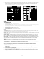
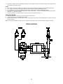
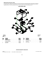
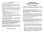
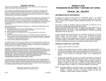
MODEL 9520 & 9520GS
6/12 VOLT, 0-20 AMP - BATTERY CHARGER
OWNER'S MANUAL
IMPORTANT SAFETY INSTRUCTIONS
SAVE THESE INSTRUCTIONS:
This manual contains important safety and operating instructions for the battery charger you have
purchased. You may need to refer to these instructions at a later date.
CAUTION: To reduce the risk of injury, charge only lead acid type rechargeable batteries (Lead accumulator battery). Other types of
batteries may burst, causing personal injury and property damage.
WARNING-RISK OF EXPLOSIVE GASES
WORKING IN THE VICINITY OF A LEAD-ACID OR OTHER AUTOMOTIVE BATTERY IS DANGEROUS. BATTERIES GENERATE
EXPLOSIVE GASES DURING NORMAL BATTERY OPERATION. FOR THIS REASON, IT IS OF UTMOST IMPORTANCE THAT EACH
TIME, BEFORE USING YOUR CHARGER, YOU READ THIS MANUAL AND FOLLOW THE INSTRUCTIONS EXACTLY.
An extension cord should not be used unless absolutely necessary. Use of an improper extension cord could result in the risk of fire and
electric shock. If an extension cord must be used, make sure:
a. That it has a protective conductor (earthed) and a minimum cross section of 1.5mm2 in accordance with local electrical safety codes.
b. For industrial and agricultural usage, use only electrical extension cords approved for these operations.
1.
PREPARING TO CHARGE:
a.
b.
c.
d.
2.
DC CONNECTION PRECAUTIONS
a.
b.
3.
Connect and disconnect the DC output clamps only after setting the AC Power switch to the « F » (OFF) position and removing the
AC cord from the electric outlet. Never allow the clamps to touch each other.
When attaching a clamp to a battery post, twist or rock the clamp back and forth several times to make a good connection.
FOLLOW THESE STEPS WHEN CONNECTING THE BATTERY
a.
b.
c.
d.
e.
f.
g.
4.
Be sure the area around the battery is well ventilated while the battery is being charged.
Clean the battery terminals.
Add distilled water in each cell until the battery acid reaches the level specified by the battery manufacturer. The normal level is
usually 1 cm above the lead plates.
Determine the voltage of the battery by referring to the vehicle owner's manual and make sure that the output voltage selector
switches are set at the correct voltage. If the charger has an adjustable charge rate, charge the battery initially at the charger's
lowest rate for the battery.
Check the polarity of the battery posts. The Positive (POS,P,+) battery post usually has a larger diameter then the Negative (NEG,N,) battery post.
Determine which post of the battery is grounded (connected to the chassis). If the negative post is grounded to the chassis (as in
most vehicles), see paragraph 4c. If the positive post is grounded to the chassis, see paragraph 4d.
For a Negative ground vehicle, double check the polarity of the battery terminals. Connect the Positive (Red) clamp from the battery
charger to the Positive (POS,P,+) ungrounded post of the battery. Connect the Negative (Black) clamp to the vehicle chassis, a
heavy gauge metal part of the frame or the engine block, away from the battery. Do not connect the clamp to the carburetor, fuel
lines or sheet metal part of the frame.
For a Positive ground vehicle, double check the polarity of the battery terminals. Attach the Negative (Black) clamp to the Negative
(NEG,N,-) ungrounded post of the battery. Attach the Positive (Red) clamp to the vehicle chassis, a heavy gauge metal part of the
frame or the engine block, away from the battery. Do not connect the clamp to the carburetor, fuel lines or sheet metal part of the
frame.
When disconnecting the charger, follow these precautions:
!
Turn the AC Power Switch to the « F » (OFF) position.
!
Disconnect the AC cord.
!
Remove the clamp from the vehicle chassis.
!
And then remove the clamp from the battery terminal.
See section 4, LENGTH OF CHARGE, for information on length and rate of charge.
A marine (boat) battery must be removed and charged on shore. To charge it on-board requires equipment specially designed for
marine use.
LENGTH OF CHARGE
a.
b.
c.
Use a temperature compensating hydrometer or a voltmeter to determine the State of Charge of the battery. Do not charge a battery
that is over 75% charged or if the battery is determined to be defective. Refer to the STATE OF CHARGE TABLE.
Determine the Battery Size,(Small, Medium or Large). Refer to the BATTERY SIZE table.
Refer to the CHARGE RATE Vs MINUTES CHARGE table to determine the recommended length of charge for the battery based on its
size, state of charge and the charging amperes.
13
d.
Discontinue charging when the specific gravity of the electrolyte reaches 1,260 or above. A temperature compensating hydrometer
should be used for this reading. Discontinue charging if the battery begins to gas excessively or when the temperature of the
electrolyte reaches approximately 590 C. Do not overcharge the battery.
OPERA
TING INSTRUCTIONS
*
CONTINUOUS RED LIGHT - Indicates AC power is on.
*
CONTINUOUS GREEN LIGHT - Indicates correct connection. If when battery is connected, the green light does not light, check for
proper polarity or poor connections. If the battery voltage is below 2 volts the green light will not come on.
*
CONTINUOUS YELLOW LIGHT - Indicates charging.
*
BLINKING GREEN LIGHT - Indicates charging is complete.
NOTES:
THREE SECOND DELAY - To avoid sparking, the charger control tests for correct polarity before applying current to the battery. When
connected properly, the green light will come on for 3 seconds before the yellow light comes on.
BATTERY TEST - After the 3 second delay the charger control will begin a 6 second battery test. The yellow light will be on and the meter
will indicate low current.
BATTERY CHARGE - After testing the battery, the control will select a charging rate suitable for the voltage and state of charge of the
battery. A small battery, or a nearly charged battery will cause the charger to rapidly step down in current to avoid heating and gassing.
FINISH CHARGE - In order to reach a 100 % state of charge on the battery, a 3 hour finish cycle has been programmed into the charger
control. During this cycle, if the battery voltage does not change over a fixed period of time the charger shuts off and the green light
comes on.
TIME OUT - An 11 hour timer will terminate the charging cycle if for some reason 100 % state of charge has not been reached.
COOLING FAN - When charging current exceeds 10 amps the cooling fan will come on to keep the electronics from overheating. Below
10 amps the fan shuts off. The fan will also come on briefly when the AC power first comes on.
BATTERY MAINTAINER - If the charger is left connected to the battery, it will begin recharging if the terminal voltage falls below 12.44
VDC. It is recommended that the electrolyte level be checked regularly when charging batteries for an extended period of time.
OPERATING PROCEDURE:
1.
2.
3.
4.
Plug AC cord into outlet. Turn AC Power Switch on back of cabinet to the ON « I » position. The Red light should come on and the
fan will run briefly.
Put selector switch in the CHARGE position.
Connect the BLACK clamp to the negative (-) terminal of the battery. Connect the RED clamp to the positive (+) terminal of the
battery. The GREEN light should come on for 3 seconds.
The YELLOW light will come on when the GREEN light goes off. After a 6 second battery test charging will begin. The amount of
charging current can be observed on the meter.
14
5.
The battery is charged when the GREEN light is blinking. If a 100 % state of charge is not needed the battery can be used when the
meter indicates low charging current.
NOTES:
a. If the charger is connected to a battery which will not accept a charge, the charging cycle will end and the GREEN light will blink.
b. If the charger is connected to a fully charged battery the charger will shut off and the GREEN light will blink.
c. If the clamps are removed during the battery test sequence the charger will shut off and the GREEN light will blink.
d. It is best to reset the charger control before beginning to charge another battery. This can be accomplished by pulling the AC Power
Switch OFF « F » then ON « I » again.
e. Any time a malfunction is suspected reset the control by turning the AC Power Switch OFF « F ».
VEHICLE STARTING:
1.
2.
3.
Charge the battery for a minimum of 10 minutes using the procedure above.
Put the selector switch in the ENGINE START position.
Attempt to start the vehicle. If the engine does not start, put the selector switch back to the CHARGE position for another 10 minutes
before trying again.
NOTE: The output circuit breaker may open during the engine start. It will reset in a few seconds and battery charging will continue.
WIRING DIAGRAM
15
MAINTENANCE INSTRUCTIONS
Worn clamps, cords or cables should be replaced. Worn parts can lead to poor connections and present a safety hazard. See parts list
for order numbers of service parts. Any maintenance or repair of this unit that involves disassembly of the cabinet should be done be a
qualified serviceman. Incorrect reassembly may result in a risk of electric shock when unit is subsequently used.
EXPLODED VIEW
9520 &
REPAIR
LIST
Item
1
2
3
4
5
9520GS
PART
Description
Handle . . . . . . . . . . . . . . . . . . . . . . . . . . . . . . . . . . .
Cabinet Top 9520 . . . . . . . . . . . . . . . . . . . . . . . . . . .
Cabinet Top 9520GS . . . . . . . . . . . . . . . . . . . . . . . .
Transformer 9520 . . . . . . . . . . . . . . . . . . . . . . . . . . .
Transformer 9520GS . . . . . . . . . . . . . . . . . . . . . . . .
Circuit Board . . . . . . . . . . . . . . . . . . . . . . . . . . . . . .
Rate Switch . . . . . . . . . . . . . . . . . . . . . . . . . . . . . . .
Part No.
610619
610755
610756
610686
610678
610679
610620
Item
6
7
8
9
10
11
Description
Cabinet Base . . . . . . . . . . . . . . . . . . . . . . . . . . . . . .
AC Cord . . . . . . . . . . . . . . . . . . . . . . . . . . . . . . . . . .
DC Cable Set . . . . . . . . . . . . . . . . . . . . . . . . . . . . . .
Stand-Off (set of 2) . . . . . . . . . . . . . . . . . . . . . . . . . .
Amp Meter . . . . . . . . . . . . . . . . . . . . . . . . . . . . . . . .
Power Switch . . . . . . . . . . . . . . . . . . . . . . . . . . . . . .
Part No.
610884
610614
610886
610759
610685
610621
ASSOCIATED EQUIPMENT CORPORATION
5043 FARLIN AVENUE ST. LOUIS MO 63115
W1960
ILLUSTRATION LIST 27-550E
Rev. 06/98 027-0550
9520 & 9520GS - ENGLISH SECTION
16
FIG
1
2
3
Filename
ENG-TABL.PLT
37-511E.PLT
A4385.PLT
Description
CHARGE RATE TABLE - ENGLISH
WIRING DIAGRAM YAH1220
EXPLODED VIEW 9520
DOCUMENT LISTING 027-0550 - 9520 / 9520GS OWNERS MANUAL
DOC No.
FILENAME
DESCRIPTION
1
27-550G.MAN
GERMAN LANGUAGE SECTION PG 1 - 4
2
27-550D.MAN
DUTCH LANGUAGE SECTION PG 5 - 8
3
27-550F.MAN
FRENCH LANGUAGE SECTION PG 9 - 12
4
27-550E.MAN
ENGLISH LANGUAGE SECTION PG 13 - 16
DO NOT COMBINE INDIVIDUAL FILES INTO ONE DOCUMENT. THE FILE SIZE BECOMES UNMANAGEABLE AND THE COMPUTER
SLOWS TO A CRAWL.
Revision record
11/94 first printing
05/98 (A4385.plt graphic change) (6digit p/n# for base was 610754 is 610884)(DC cable 610886 was 610760)
17