1
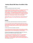
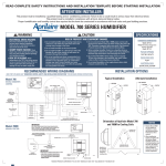
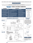
Steam Humidifier
Model 800 Residential Steam Humidifier
Owner’s Manual
Includes Safety & Operating Instructions
and Warranty Information
READ AND SAVE THESE INSTRUCTIONS
TABLE OF CONTENTS
CAUTION
Safety Cautions . . . . . . . . . . . . . . . . . . . . . . . . . . . . . . . . . . . . . . . . . . . . . . . 2
Introduction . . . . . . . . . . . . . . . . . . . . . . . . . . . . . . . . . . . . . . . . . . . . . . . . . . 4
Principles of Operation . . . . . . . . . . . . . . . . . . . . . . . . . . . . . . . . . . . . . . . . . 4
Sequence of Operation . . . . . . . . . . . . . . . . . . . . . . . . . . . . . . . . . . . . . . . . . 5
Operating Modes . . . . . . . . . . . . . . . . . . . . . . . . . . . . . . . . . . . . . . . . . . . . . 6
Display Panel . . . . . . . . . . . . . . . . . . . . . . . . . . . . . . . . . . . . . . . . . . . . . . . . 7
Operating Instructions – Digital Humidifier Control . . . . . . . . . . . . . . . . . . 9
• Digital Humidifier Control Indicator Lights . . . . . . . . . . . . . . . . . . . . . . 9
• Blower Activation . . . . . . . . . . . . . . . . . . . . . . . . . . . . . . . . . . . . . . . . . 9
• Automatic Mode . . . . . . . . . . . . . . . . . . . . . . . . . . . . . . . . . . . . . . . . . 10
• Manual Mode . . . . . . . . . . . . . . . . . . . . . . . . . . . . . . . . . . . . . . . . . . . 11
Check the Humidifier Operation . . . . . . . . . . . . . . . . . . . . . . . . . . . . . . . . . 13
Additional Information . . . . . . . . . . . . . . . . . . . . . . . . . . . . . . . . . . . . . . . . 14
Effect of Water Characteristics . . . . . . . . . . . . . . . . . . . . . . . . . . . . . . . . . 14
Maintenance . . . . . . . . . . . . . . . . . . . . . . . . . . . . . . . . . . . . . . . . . . . . . . . . 14
Limited Warranty . . . . . . . . . . . . . . . . . . . . . . . . . . . . . . . . . . . . . . . . . . . . 16
SAFETY CAUTIONS
CAUTION
Attention Installer
Read this manual before installing. This product must be
installed by qualified HVAC and electrical contractors and in
compliance with local, state, federal, and governing codes.
Improper installation can cause property damage, severe
personal injury, or death as a result of electric shock, burns,
or fire.
Read all cautions and instructions.
Read this manual before performing service or maintenance
procedures on any part of the system. Failure to follow all
cautions and instructions could produce the hazardous
situations described, resulting in property damage, personal
injury, or death.
Failure to follow the instructions in this manual can cause
moisture to accumulate, which can cause damage to structure
and furnishings.
-2-
Hot surfaces and hot water
This steam humidification system has extremely hot surfaces.
Water in steam canister, steam pipes, and dispersion tube can be
as hot as 212°F (100°C). Discharged steam is not visible. Contact
with hot surfaces, discharged hot water, or air into which steam
has been discharged can cause severe personal injury. To avoid
severe burns, follow procedures in this manual when performing
service or maintenance procedures on any part of the system.
Disconnect electrical power
Disconnect electrical power before installing supply wiring or
performing service or maintenance procedures on any part
of the humidification system. Failure to disconnect electrical
power could result in fire, electrical shock, and other hazardous
conditions. These hazardous conditions could cause property
damage, personal injury, or death.
Contact with energized circuits can cause property damage,
severe personal injury, or death as a result of electrical shock
or fire. Do not remove access panels until electrical power is
disconnected.
Follow the shutdown procedure in this manual before performing
service or maintenance procedures on any part of the system.
Electrical shock hazard
If the humidifier starts up responding to a call for humidity during
maintenance, severe bodily injury or death from electrical
shock could occur. Follow the procedures in this manual before
performing service or maintenance procedures on this humidifier.
Excessive supply water pressure
Supply water pressure greater than 120 psi may cause the
humidifier to overflow.
SHARP EDGES
Sharp edges may cause serious injury from cuts. Use care when
cutting plenum openings and handling ductwork.
EXCESS HUMIDITY
Do not set humidity higher than recommended. Condensation
may cause damage.
-3-
INTRODUCTION
Figure 1 – Fill and Drain System and Canister
Thank you for your recent Aprilaire humidifier purchase. We appreciate
your business and are pleased to add your name to our growing list of
customers. You have invested in the highest quality equipment available.
Aprilaire manufactures whole-house indoor air quality products and is a
recognized leader in the heating and air conditioning industry.
®
Steam
Outlet
Fill Cup
Overflow
Your humidifier will require periodic maintenance to assure continued
consistent performance. See page 14.
Now, please take a few minutes and read this booklet. This will familiarize
you with the benefits you will receive from the equipment you just purchased
and help you understand the routine maintenance that will be required.
Be sure to register your humidifier warranty online at:
www.aprilaire.com/warranty.
High Water
Level Sensor
Electrodes
Flow Control
Orifice
Canister
Genuine Aprilaire Replacement Model 80 Steam Canisters are
available from your installing contractor or from most other heating
and air conditioning contractors in your area. Use the dealer locator on
our web site (www.aprilaire.com) or look in the Yellow Pages under
Humidifying Apparatus or Heating & Air Conditioning Contractors.
Fill
Inlet
Fill Valve
Drain Valve
Drain Cup
PRINCIPLES OF OPERATION
The Aprilaire® Model 800 Canister Steam Humidifier delivers humidity in the
form of steam to the conditioned space via the HVAC system duct or optional
Aprilaire Model 850 Fan Pack. The humidifier generates steam by energizing
two electrodes that extend into a canister of water. Current flowing between
the electrodes causes the water to boil, creating steam. Water is introduced
to the humidifier through a fill valve to a fill cup located in the top of the
cabinet. The fill cup serves as an overflow reservoir and provides an air gap
between the humidifier and water source. The steam canister is filled from
the bottom. The canister is seated in a drain cup assembly which includes a
drain valve. The drain and fill valves work together to maintain water level
in the canister to deliver the rated steam capacity based on the electrical
conductivity of the water and to temper drain water. See Figure 1 for
representation of fill and drain system and canister.
Steam is delivered into the airstream through a dispersion tube mounted
in the HVAC system ductwork. Openings in the dispersion tube are fitted
with “tubelets” which extend into the center of the tube. The design of the
dispersion tube and tubelets distribute steam over a wide area in the duct
and direct any condensed moisture back into the steam hose.
-4-
Supply
Water
Drain
90-1522
SEQUENCE OF OPERATION
When the Automatic Digital Humidifier Control (ADHC) detects humidity
below the set point, and provided the humidifier is turned on and the
HVAC system blower is operating, the internal controller in the humidifier
energizes the electrodes and measures the current flowing through the
water between them. The controller adjusts water level in the canister via
a fill valve and a drain valve to maintain a constant current. The operating
water level in the canister depends on the mineral content of the water
which determines conductivity.
The ADHC has the ability to turn on the HVAC system blower if the
homeowner or installer chooses to utilize that feature. See ADHC
installation manual.
-5-
OPERATING MODES
DISPLAY PANEL
When the humidifier is powered and turned on, the “On/Off” light is
illuminated green.
Any time the fill valve is activated, the “Fill” light illuminates green.
TABLE 1 – Display Panel
Icon
Any time the drain valve is activated, the “Drain” light illuminates green.
During initial start up with a new canister, the humidifier may run through
a series of fill/drain cycles until the conductivity of the water is in a
range that allows normal operation. During this time, the “Steam” light
illuminates green. If the humidifier cannot produce steam at the rated
level after trying for 48 hours, the “Steam” light illuminates yellow. The
humidifier continues to attempt to produce steam at the rated level for
another 48 hours in this mode. If the humidifier cannot produce steam at
the rated level in a total of 96 hours, the “Service” light will flash red.
The conductivity of naturally soft water, hard water, and softened water
changes as the water heats up, but the controller adjusts the water level
to maintain a nominal current between the electrodes. Over the life of the
canister, minerals that build up on the electrodes will reduce their effective
surface area and affect the resistance between them. The operating water
level will increase with use until it reaches the high water level probe. At
that point, the “Service” light will flash red indicating that the canister
needs to be replaced.
Main switch. Press to turn humidifier on and off.
Resets timer for start-up water conditioning.
Solid green when humidifier is turned on.
Light
Solid green during normal operation when canister water is
being replenished.
Light
Flashes green (along with Drain light) indicating fill and
drain valves are pulsing to dislodge mineral deposits.
Solid red if canister needs water but water is not detected.
See Troubleshooting Guide.
Indicates call for humidity.
Solid green during call for humidity.
Any time power is disconnected or humidifier is turned off, the internal
timer for start-up and drain cycles is reset.
If the humidifier is operating and a power failure occurs, once power
is restored, the “On/Off” light will flash green for one minute, then the
humidifier will turn on.
Flashes green for one minute once power is restored if
humidifier was operating when power was shut off.
Fill valve indicator.
When the humidifier is operating, the “Steam” light on the front illuminates
green. If the internal controller attempts to make steam but the water does
not contain enough minerals to be conductive, the water level in the tank
will reach the high level point and the “Steam” light will illuminate yellow.
If the humidifier has operated 168 hours without a drain cycle, the drain
valve will open and drain the canister. Normal operation will continue.
Function
Light
Solid yellow if humidifier cannot reach nominal output
within first 48 hours of operation due to insufficient water
conductivity. Humidifier will continue to cycle valves in
an attempt to reach capacity for an additional 48 hours.
Approximately 1/10 teaspoon of table salt can be added to
fill cup to increase conductivity of water.
End of Season/Period of Inactivity Shut-down
If the humidifier does not receive a call to operate in 72 hours, the
controller drains the canister. The humidifier will resume normal operation
when a call for humidity is made.
-6-
-7-
TABLE 1 – Display Panel (continued)
Icon
Function
OPERATING INSTRUCTIONS – digital humidifier control
The Digital Humidifier Control offers two modes of operation, Automatic or
Manual. An explanation of both modes follows. (See Figure 2 on page 10 for
Automatic Mode. See Figure 3 on page 11 for Manual Mode.)
Drain valve indicator.
When in the Automatic Mode, this system offers the following benefits:
Light
Solid green to indicate start of drain cycle.
Drain cycle occurs:
1) To maintain nominal steam output during normal
operation.
2) During end of season shut down. (End of season shut
down occurs after 72 hours of inactivity.)
3) If humidifier has operated for 168 hours without a drain
cycle.
4) When humidifier is turned off.
Flashes green (along with fill light) indicating drain and fill
valves are pulsing to dislodge mineral deposits.
Flashes green when humidifier is turned off indicating
canister is draining. When flashing stops, main power
disconnect can be turned off and front panel can be opened.
Indicates canister needs to be replaced or humidifier
requires other type of service.
Flashes red when canister can no longer supply demand
and needs to be replaced because electrodes have been
corroded or coated with mineral deposits. Humidifier may
continue to generate steam but at a reduced capacity.
Light
Flashes red if humidifier with new canister cannot generate
steam due to insufficient water conductivity after 96 hours of
drain/fill activity. Approximately 1/10 teaspoon of table salt
can be added to fill cup to increase conductivity of water.
Solid red if controller detects over-current between
electrodes. Causes may include electrodes coated with
mineral deposits, blocked drain, or defect in drain valve
circuit. See Troubleshooting Guide.
-8-
• You will receive the optimum amount of humidity so that your
home and its furnishings are protected from the damaging effects
of excess condensation or low humidity during the heating
season. The Control automatically adjusts your home’s humidity based
on the outdoor temperature, increasing the time maximum comfort is
maintained.
• Simple operation with few adjustments. In the Automatic Mode, the
Control eliminates the need to manually adjust the control when outdoor
temperature changes. It also eliminates the need to turn the dial setting to
“OFF” during the summer season.
Digital Humidifier Control Indicator Lights
Call Dealer for Service: The red light indicates that the humidifier is not
operating normally and that service is required.
Humidifier On: The green light indicates that the humidifier is operating
normally.
Blower Activation
Set the Blower Activation Switch to “ON” to allow the Humidifier Control
to activate the furnace fan for additional humidification. Refer to TABLE 4 –
Operation Guide. This may be required if the humidifier is mounted on a
heat pump or a furnace with short run cycles.
When the Blower Activation switch is “ON”, the Humidifier Control will turn
on the HVAC blower when humidity is required. In the “OFF” position, the
humidifier will only operate if humidity is required and the HVAC system is
operating.
When the Blower Activation switch is “ON”, the Humidifier Control may
periodically turn the HVAC blower on to sample the humidity of the air.
-9-
Automatic Mode
Manual Mode
Figure 3 – Manual Mode
Figure 2 – Automatic Mode
90-1235B
Your Aprilaire Humidifier Control is installed in the cold air return duct.
During the first heating season, your Humidifier Control needs to be set
initially to match your home’s condition. Please follow these steps when
adjusting your control (refer to Figure 2).
1. Turn the dial setting knob to “5”, which is within the normal range.
During the next 24-48 hours it may be necessary to adjust the dial for
more or less humidity, depending on your personal comfort and home’s
requirements. Refer to TABLE 4 – Operation Guide.
2. During the coldest portion of the first heating season, minor adjustments
may be necessary. This is dependent upon your home’s construction.
Refer to TABLE 4 – Operation Guide.
The humidity in your home will now be accurately controlled to meet
your needs and should not need further adjustment during future heating
seasons. Make note of the dial setting in the event you temporarily move
the knob to “OFF” when performing annual maintenance of your Aprilaire
humidifier.
90-1236B
When installed in the Manual Mode (see Figure 3 – internal switch in “MAN”
position and “M” in the display), it is important to anticipate a drop in outdoor
temperature and reduce the setting accordingly to avoid excessive condensation.
For example, with an outdoor temperature of 20°F the correct setting will be
35%. If the temperature is expected to fall to 0°F that evening, then merely
reduce the setting to 25% several hours prior to the temperature change.
See Table 2 for the recommended settings. These settings, which are based
on years of research, represent a compromise between humidity levels that
would be most desirable for comfort and humidity levels that are suitable
for protection of your home and to avoid condensation on your windows. For
example, a wintertime indoor humidity of 50% may be considered ideal for
comfort, but unfortunately, it probably would result in condensation, which can
cause damage to your home. Observing the recommended humidity levels on
your Humidifier Control is an important safeguard. Condensation of water on the
inside surface of windows in the form of fogging or frost is usually an indication
of too much humidity. This same condensation can occur in other areas in your
home, possibly resulting in damage.
Table 2 – Outdoor Temperature/ Indoor Relative Humidity
- 10 -
Outside Temperature +40°F
+30°F
+20°F
+10°F
0°F
–10°F
–20°F
Recommended RH
45%
40%
35%
30%
25%
20%
15%
- 11 -
Test/Reset
Table 4 – Operation Guide
The Test/Reset feature allows the humidifier operation to be checked even
if there is no call for humidity. See “Check the Humidifier Operation” on
page 13.
Condition
Solution
Condensation on windows.
Reduce the setting on the control dial by
1 increment.
Additional Information – AUTOMATIC MODE
Lack of humidity.
Increase the setting on the control dial by
1 increment.
Humidifier does not turn on.
Turn dial to “Test/Reset”. Make certain
HVAC blower is operating. If unit still does
not operate, consult a heating contractor.
The Digital Humidifier Control will accurately control the humidity in your
home to a maximum of 45%.
Humidifier won’t shut off.
The humidity Values in Table 3 are targets based on outdoor temperature
and the Digital Humidifier Control setting. The actual humidity may vary due
to conditions in the home (cooking, showering, etc.).
Turn control dial to “Off”. If unit continues
to produce steam, turn off the humidifier
and consult a heating contractor.
Test mode.
System operation is checked by setting
the knob to “Test/Reset”. Make certain
HVAC blower is operating. Humidifier will
operate for one minute.
Red “Call Dealer for Service”
light flashes (Figure 2).
Note the error code on the display (E1,
E2, E3 or E4) and call your heating and air
conditioning dealer.
1
2
3
4
5
6
7
Table 3 – % Relative Humidity Guide
Outdoor Temperature (°F)
-10°F 0°F 10°F 20°F 30°F
10% 10% 10% 15% 20%
10% 10% 15% 20% 25%
10% 15% 20% 25% 30%
15% 20% 25% 30% 35%
20% 25% 30% 35% 40%
25% 30% 35% 40% 45%
30% 35% 40% 45% 45%
40°F
25%
30%
35%
40%
45%
45%
45%
Relative Humidity (%)
Dial Setting
Your humidifier is a precision system that will accurately maintain the
humidity in your home. For every 2°F change in outdoor temperature, the
Digital Humidifier Control will automatically adjust the indoor humidity by
1%.
Check the Humidifier Operation
Digital Humidifier Control
Set the knob to “Test/Reset”, make sure that the water saddle valve is
open and that the humidifier is on. The HVAC fan must be running for the
humidifier to function. The humidifier will only operate for 1 minute in test
mode. Reduce the Humidifier Control setting to the recommended inside
humidity, depending on the outside temperature. Do not leave in test
mode as humidifier will not operate.
- 12 -
- 13 -
To Replace the Canister
additional information
Be sure to keep fireplace dampers closed when not in use. They provide an
excellent escape route for heat, as well as humidity.
Replace the canister annually and when prompted by the “Service” light.
Use Only Genuine Aprilaire Model 80 Canister.
On occasion, indoor moisture producing activities such as clothes drying,
cooking, showers, etc., may raise the humidity level higher than it should be,
even though the Aprilaire humidifier is not operating. Telltale indications are
condensation or frost on cold surfaces such as windows, doors, walls, etc. If
such condensation persists for several hours, your home should be ventilated
to dissipate the potentially damaging excess moisture.
1.Press On/Off switch to turn humidifier off.
EFFECT OF WATER CHARACTERISTICS
Your humidifier is designed to operate using softened or unsoftened, cold
tap water. Do not use hot water.
2.Allow humidifier to drain. When the green “drain” LED stops flashing,
disconnect main electrical power to humidifier.
3.Remove front panel.
4.Pull three wires off posts on top of canister. (Two large electrode
conductors and one water level probe conductor.)
5.Loosen hose clamp at top of canister.
6.Slide hose off top of canister.
7.Slide canister up and out of drain assembly. Discard canister.
8.Remove o-ring from drain assembly using small screw driver.
9.Inspect drain assembly and remove any debris. See drain valve cleaning
procedure.
MAINTENANCE
Turn humidifier off and allow humidifier to drain. Disconnect power
before servicing.
10.Insert new o-ring into slot in drain assembly. (O-ring is provided
with Model 80 canister.) Dampen o-ring with water before inserting
canister. Do not use oil, grease, or any lubricant besides water.
Inspect Humidifier at approximately 500 hour intervals or several times
during the humidification season.
11.Make sure strainer is inserted into bottom of new canister.
• Check system operation and inspect all plumbing connections and piping
for signs of cracks or leaks.
12.Insert canister into drain assembly. Position canister with label facing
outward.
13.Slip steam hose over top of canister and tighten hose clamp.
• Inspect drain line to make sure it is not blocked and has constant
downward slope. Clean or replace if necessary.
14.Reattach three wires to posts on top of canister. (Larger electrode
conductors are interchangeable.)
• Inspect steam hose to make sure it has no low spots and has constant
upward slope from humidifier to dispersion tube in duct. If dispersion
tube is mounted below humidifier, inspect drip tee drain.
15.Replace front panel.
16.Inspect drain line to make sure it is not blocked and has constant
downward slope. Clean or replace if necessary.
17.Inspect steam hose to make sure it has no low spots and has constant
upward slope from humidifier to dispersion tube in duct. If dispersion
tube is mounted below humidifier, inspect drip tee drain.
18.Restore electrical power to humidifier.
19.Turn humidifier on and verify green On/Off light is illuminated.
20.See Start-up procedure.
To Service Fill Valve
If water flow from fill valve is restricted, disconnect inlet fitting and remove
in-line strainer using small screw from inlet port. Clean or replace strainer.
- 14 -
- 15 -
Limited Warranty
Your Research Products Corporation Aprilaire humidifier unit is expressly warranted for five
(5) years from date of installation to be free from defects in materials or workmanship except,
however, for the disposable steam canister which will have to be replaced from time to time
depending upon the amount of use.
®
Research Products Corporation’s exclusive obligation under this warranty shall be to supply,
without charge, a replacement for any part of the humidifier which is found to be defective within
such five (5) year period and which is returned not later than thirty (30) days after said five (5)
year period by you to either your original supplier or to Research Products Corporation, Madison,
Wisconsin 53701, together with the model number and installation date of the humidifier.
THIS WARRANTY SHALL NOT OBLIGATE RESEARCH PRODUCTS CORPORATION FOR ANY LABOR
COSTS AND SHALL NOT APPLY TO DEFECTS IN WORKMANSHIP OR MATERIALS FURNISHED BY
YOUR INSTALLER AS CONTRASTED TO DEFECTS IN THE HUMIDIFIER ITSELF.
IMPLIED WARRANTIES OF MERCHANTABILITY OR FITNESS FOR A PARTICULAR PURPOSE
SHALL BE LIMITED IN DURATION TO THE AFORESAID FIVE YEAR PERIOD. RESEARCH PRODUCTS
CORPORATION’S LIABILITY FOR INCIDENTAL OR CONSEQUENTIAL DAMAGES, OTHER THAN
DAMAGES FOR PERSONAL INJURIES, RESULTING FROM ANY BREACH OF THE AFORESAID
IMPLIED WARRANTIES OR THE ABOVE LIMITED WARRANTY IS EXPRESSLY EXCLUDED.
THIS LIMITED WARRANTY IS VOID IF DEFECT(S) RESULT FROM FAILURE TO HAVE THIS UNIT
INSTALLED BY A QUALIFIED HEATING AND AIR CONDITIONING CONTRACTOR. IF THE LIMITED
WARRANTY IS VOID DUE TO FAILURE TO USE A QUALIFIED CONTRACTOR, ALL DISCLAIMERS
OF IMPLIED WARRANTIES SHALL BE EFFECTIVE UPON INSTALLATION.
Some states do not allow limitations on how long an implied warranty lasts or the exclusion or
limitation of incidental or consequential damages so the above exclusion or limitations may not
apply to you.
This warranty gives you specific legal rights and you may also have other rights which vary from
state to state.
Warranty Registration
Visit us on-line at www.aprilaire.com to register your Aprilaire product.
If you do not have on-line access, please mail a postcard with your name, address,
phone number, model number of product purchased and date of installation to:
Research Products Corporation, P.O. BOX 1467, Madison, WI 53701
Your Warranty Registration information
will not be sold or shared outside of this company.
Thank you!
RESEARCH PRODUCTS CORPORATION
PO BOX 1467 • MADISON, WI 53701-1467
10008948 6.10
B2205104A
©2010 Research Products Corporation
- 16 -