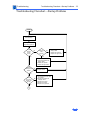
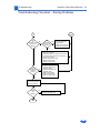
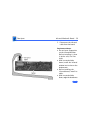
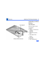
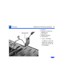
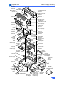
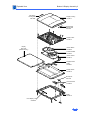
1
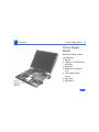
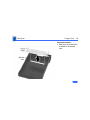
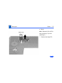
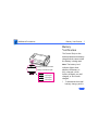
K Service Source
PowerBook 3400c/
PowerBook G3
PowerBook 3400c/180, 3400c/200, and
PowerBook G3
K Service Source
Hot Issues
PowerBook 3400/G3
Hot Issues
Overview - 1
Overview
This chapter is designed to highlight unique or highpriority product issues that you should be aware of before
servicing the PowerBook 3400 and PowerBook G3.
This chapter alerts you to important issues and provides
links to other areas in the manual where more complete
information can be found. This chapter is not intended to
replace other parts of this manual; it merely provides a
pointer to pertinent information in those chapters.
The date the Hot Issue was published is indicated in
parentheses after the title.
Hot Issues
PowerBook 3400: Modem Driver Update - 2
PowerBook 3400: Modem Driver
Update
Issue: Customers may report one of the following problems
with their PowerBook 3400 modem:
1
2
3
The modem will not reset following a disconnect. I
sometimes have to wait 10 to 30 minutes before I can
reconnect to my service provider. Does this happen
because the modem is too hot?
When uploading a file using z-modem protocol I often get
multiple errors and my computer freezes or I get a
system error.
When I am downloading large files (2-2.5 MB) over the
modem I often get intermittent disconnects.
Hot Issues
PowerBook 3400: Modem Driver Update - 3
Solution: These problems are not heat-related. To address
these situations, Apple has released a modem driver update.
Since many users believed these issues were heat-related,
they have had many dealers replace these modems. This
driver should resolve the issues and prevent needless
hardware replacement.
The Modem Driver update is posted at the Apple Software
Updates site. Apple Software Updates can be found on the
Service Source Companion 1 CD, and online as follows:
America Online, CompuServe, ftp.info.apple.com, and
ftp.support.apple.com, www.info.apple.com, and
www.support.apple.com. The path for the update is:
Apple Software Updates
US
Macintosh
Unsupported
Hot Issues
PowerBook 3400: Modem Driver Update - 4
PB 3400 Modem Driver Update.img
PB 3400 Modem Driver Update Info
The software is in the form of a disk image and requires Disk
Copy 6.1 (or later) or Disk Image Mounter (or later).
These can be downloaded from the Utilities folder under
Macintosh in the path listed above. The Info article provides
installation instructions.
Unsupported software is provided for customers to download
and use, but it is at your own risk. Apple does not provide
technical support for unsupported software.
This revision will be supported when it is rolled into the
next official software update.
Hot Issues
PowerBook 3400: Display Cable Gasket Installation (8/97 and
PowerBook 3400: Display Cable
Gasket Installation (8/97 and 10/97)
Issue: The display cables on some PowerBook 3400
computers have been working loose from their logic board
connections. The customer-reported symptoms related to
this issue include no display image or backlight while the
computer is running.
Solution: The solution in the 8/97 Hot Issue was to install a
foam gasket to the underside of the brightness and speaker
grill to keep the cable connector in place. In fact, the foam
gasket is not available as a service part and cannot be
ordered separately.
If customers report symptoms related to a loose PowerBook
3400 display cable—intermittent or no display image/
backlight—service providers should replace the brightness
Hot Issues
PowerBook 3400: Battery Gasket Installation (8/97) - 6
and speaker grill, part number 922-2488. All service
grills come with the foam gasket installed.
PowerBook 3400: Battery Gasket
Installation (8/97)
Issue: A small number of PowerBook 3400 computers
running on battery power have unexpectedly shut down when
jostled or when pressure was applied to the battery area.
The problem is due to intermittent battery contact.
Solution: If a PowerBook 3400 exhibits the above problem,
Apple recommends adding a foam gasket to the inside of the
battery bay to improve battery contact. The gasket is
available free of charge in a user-installable kit. To order
the kit, customers may call 1-888-273-3594.
Alternatively, service providers may install the gasket for
Hot Issues
PowerBook 3400: Battery Gasket Installation (8/97) - 7
customers and can order the kit as service part number
076-0706. The installation is a warranty repair.
For instructions on installing the Battery Gasket, see
“Battery Gasket Installation” in the Additional Procedures
chapter of this manual.
K Service Source
Basics
PowerBook 3400c/PowerBook G3
Basics
Product Overview - 1
Product Overview
®
PowerBook 3400c
The PowerBook 3400c
computer is an all-in-one
notebook with several
features that greatly
increase its performance.
Its 603e microprocessor
runs at a clock frequency of
180, 200 or 240 MHz. In
addition to the 256K L2
cache, the PowerBook
3400c comes with 16 MB of
RAM and is upgradeable to
144 MB.
Basics
Product Overview - 2
The system includes a 1, 2, or 3 GB hard drive, optional CDROM drive, and standard 1.44 MB floppy drive. And, with its
12.1" display, the screen is larger than previous
PowerBook displays.
PowerBook G3
The PowerBook G3 is based on the PowerBook 3400c, but
due to its 250-MHz PowerPC G3 processor, L2 backside
cache, and improved bus speed, the PowerBook G3 is
approximately twice as fast as the 240-MHz PowerBook
3400c. The PowerBook G3 also includes more RAM on
board, a higher powered battery, and a larger hard drive
than the PowerBook 3400c. In addition, the PowerBook G3
is shipping with MacOS 8, which is optimized to run with
the G3 processor. The combination of these features results
in PowerBook G3 break-through performance.
Basics
System Configurations - 3
System Configurations
The PowerBook 3400c and G3 come in these configurations:
PowerBook 3400c/180 (February ‘97)
• Processor: 180-MHz PowerPC 603e
• RAM: 16 MB
• Drives: 1 GB hard drive; 1.44 floppy drive; optional 6x
CD-ROM drive
• Display: 12.1-inch SVGA
PowerBook 3400c/200 (February ‘97)
• Processor: 200-MHz PowerPC 603e
• RAM: 16 MB
• Drives: 2 GB hard drive; 1.44 floppy drive; 6x CD-ROM
drive
• Display: 12.1-inch SVGA
• Modem: EtherNet/modem card
Basics
System Configurations - 4
PowerBook 3400c/240 (March ‘97)
• Processor: 240-MHz PowerPC 603e
• RAM: 16 MB
• Drives: 3 GB hard drive; 1.44 floppy drive; 12x CDROM drive
• Display: 12.1-inch SVGA
• Modem: EtherNet/modem card
PowerBook G3 (November ‘97)
• Processor: 250-MHz PowerPC G3
• Cache: L2 backside cache
• RAM: 32 MB
• Drives: 5 GB hard drive; 1.44 floppy drive; 20x CDROM drive
• Display: 12.1-inch SVGA
• Modem: EtherNet/modem card
Basics
Repair Strategy - 5
Repair Strategy
Service the PowerBook 3400c and PowerBook G3 through
module exchange and parts replacement. Customers can
request on-site service from an Apple Authorized Service
Provider Plus (AASP+) Apple Assurance (US only), or
request a courier through the Apple Canada Technical
Answerline (Canada only). They can also choose carry-in
service from an AASP.
Ordering
Apple Service Providers planning to support the computer
systems covered in this manual may purchase Service
modules and parts to develop servicing capability. To order
parts, use the AppleOrder (US only) or ARIS (Canada only)
system and refer to “Service Price Pages.”
Basics
Repair Strategy - 6
Large businesses, universities, and K-12 accounts must
provide a purchase order on all transactions, including
orders placed through the AppleOrder (US only) or ARIS
(Canada only) system.
USA Ordering
US Service Providers not enrolled in AppleOrder may fax
their orders to Service Provider Support (512-9088125) or mail them to
Apple Computer, Inc.
Service Provider Support
MS 212-SPS
Austin, TX 78714-9125
For US inquiries, please call Service Provider Support at
800-919-2775 and select option #1.
Basics
Repair Strategy - 7
Canadian Ordering
Canadian Service Providers not enrolled in ARIS may fax
their orders to Service Provider Support in Canada
(1-800-903-5284). For Canadian inquiries, please call
Service Provider Support at 905-513-5782 and select
option #3.
Basics
Warranty/AppleCare/ARIS - 8
Warranty/AppleCare/ARIS
US Only
The PowerBook 3400c and PowerBook G3 are covered under
the Apple One-Year Limited Warranty. The AppleCare
Service Plan is also available for these products. Service
Providers are reimbursed for warranty and AppleCare
repairs made to these computers. For pricing information,
refer to “Service Price Pages.”
Canada Only
The PowerBook 3400c and PowerBook G3 are covered under
first-year AppleCare. The Extended AppleCare Service Plan
is also available for these products. Service Providers are
reimbursed for first-year warranty and Extended
AppleCare repairs made to these computers. For pricing
information, refer to “Service Price Pages.”
Basics
View of Front and Right Side - 9
View of Front and
Right Side
Volume Control
Sleep Indicator
®
Microphone
Stereo Speakers
Brightness Control
Floppy Drive
Expansion Bay Drive Light
Security Slot
Battery
The front of the computer
includes the following:
stereo speakers, volume
control, brightness control,
sleep indicator, and
microphone.
The right side includes the
battery, security slot,
expansion bay drive light,
and floppy drive.
Basics
View of Rear and Left Side - 10
View of Rear and
Left Side
Stereo Speaker
Sound
Output
Port
Infrared
Window
Expansion
Port
Reset Button
Printer/External
Modem Port
SCSI Port (HDI-30)
Sound
Input
Port
Two PCMCIA
card slots
PC Card
Eject Buttons
ADB Port
Power
Video Port Adapter Elevation
Feet
Port
The rear panel includes the
infrared window, reset
button, and these ports:
expansion, printer/external
modem, SCSI, video, and
power adapter.
The left side includes a
stereo speaker, two PC card
(PCMCIA) slots, PC card
eject buttons, and these
ports: sound input, sound
output, and ADB.
Basics
Logic Board - 11
(Front of 3400)
603e Microprocessor
Fan
Connector
Logic Board
Hard Drive Connector
Power
Supply
Connector
16MB
Onboard
RAM
Trackpad
Connector
RAM Card
Connector
LED
Connector
PCMCIA
Mechanism
Ethernet/
Modem Board
Connector
PCMCIA
Connector
CD-ROM or
Floppy Drive
Connector
Infrared
Connector
Keyboard
Connectors
Brightness &
Speaker
Connector
Display
Connector
The logic board includes
onboard RAM, the PCMCIA
mechanism, and numerous
connectors.
Basics
Signals on the Video Connector - 12
Signals on the Video Connector
Pin
1
2
3
4
5
6, 7, 8
9
10
11
12
13
14
15
Signal Name
Description
RED
Red video signal
GREEN
Green video signal
BLUE
Blue video signal
MONID(0)
Monitor ID signal 0
GND
DDC return
AGND_VID
Analog video ground
+5V_IO 5 V
Power for I/O device
GND HSYNC & VSYNC Ground
VGA_ID
VGA ID signal
MONID(2)
Monitor ID signal 2
HSYNC
Horizontal
synchronization signal
VSYNC
Vertical synchronization
signal
MONID(1)
Monitor ID signal 1
Basics
Battery Information - 13
Battery Information
Warning: For the main battery, use only the lithium-ion
(LiIon)battery supplied with the computer. Batteries
designed for other portable computers may look similar, but
they may not work with your computer and may damage it.
The LiIon and nickel-metal-hydride (NiMH) batteries look
similar. To distinguish them,
• Read the label on the battery, which will identify the
battery as either “LiIon” or “NiMH.”
• Look for battery indicator lights; if the battery has
them, it’s a LiIon battery.
Basics
Battery Information - 14
Main Battery
For their main batteries,
the PowerBook 3400c and
G3 use lithium ion (LiIon)
batteries. Each battery
provides power for up to
four hours of work time.
Note : Although these
batteries fit into a PowerBook 190/5300, it will not
recognize or charge them.
Note: To use the PowerBook
G3 battery in a PowerBook
3400c, you may need to
install a software update.
Basics
Battery Information - 15
Optional Battery
The PowerBook 3400c and G3 computers can also use a
nickel-metal-hydride (NiMH) battery. This battery
provides somewhat less work time; the precise amount of
work time depends on the model you have and the battery
conservation features you use.
Battery Handling Guidelines
The following are guidelines for properly handling the
PowerBook 3400c and G3 batteries:
Warning: LiIon batteries contain hazardous chemicals and
should not be thrown out with household or office trash. Take
dead batteries to an Apple authorized service provider for
recycling or proper disposal. Review battery handling and
disposal instructions in Safety Information in Bulletins/
Basics
Battery Information - 16
Safety.
• Handle the battery carefully. Do not drop, puncture,
disassemble, mutilate, or incinerate it.
• Do not leave a battery in the computer for longer than a
week without plugging in the power adapter.
• Always put the battery cap on the battery when the
battery is out of the PowerBook. The battery contacts
should not be exposed when the battery is out of the
computer.
• Do not leave the battery in hot locations (such as the
trunk of a car).
• Do not leave a battery in storage for longer than six
months without recharging it.
• Never get batteries wet.
• Do not short-circuit the battery terminals. Doing so may
cause an explosion or a fire.
• Recharge batteries only as described in the user’s manual
and only in ventilated areas.
Basics
PC Card Handling - 17
PC Card Handling
Two PC Card slots (also
known as PCMCIA slots) are
featured in the PowerBook
3400c and G3 computers.
The two slots accept a
variety of third-party PC
Cards with 68-pin
connectors.
There are three types of PC
Cards: Type I (3.3 mm),
Type II (5 mm), and Type III
(10.5 mm). Type I and Type
II cards fit in either the
upper or lower slot of the PC
Basics
PC Card Handling - 18
Card unit. Type III cards can only be placed in the lower slot.
When a Type III card is in the lower slot, the upper slot
cannot be used.
The following are guidelines for properly handling PC Cards:
• Use only cards that are compatible with the PC Card unit.
Refer to the compatibility information that came with the
card. If you cannot find the compatibility information,
call the card vendor.
• Do not insert anything other than a PC Card into the card
slots.
• The computer must be on or off in order to eject a PC
Card. When the computer is in sleep mode, a PC Card
cannot be ejected.
• Before you eject a card, make sure nothing is blocking
the card’s slot.
Basics
PC Card Handling - 19
• If you want to use the card again immediately, pull it out
about an inch more and then push it back in. If you don’t
follow this procedure and try to push the card back in to
use it again, the card will not engage properly.
• Do not pull on a PC Card before it has been ejected out of
the slot. Forcing a PC Card out of the slot may damage the
computer or the card.
K Service Source
Specifications
PowerBook 3400c /PowerBook G3
Specifications
Introduction - 1
Introduction
You can also find specifications information for this product in the
Spec Database, which you can access in one of three ways:
— Launch it directly by double-clicking the Apple Spec Database
runtime alias at the top level of the Main Service Source CD.
— Select "Apple Spec Database" from the Service Source dropdown main menu.
— Click the Acrobat toolbar icon for the database, which is near
the right end of the toolbar with the letters "SP."
Specifications
Processor - 2
Processor
CPU
PowerBook 3400c
PowerBook G3
PowerPC 603e microprocessor running at 180, 200, or 240
MHz
PowerPC G3 microprocessor running at 250 MHz
Cache
PowerBook 3400c
PowerBook G3
256K, second-level (L2) cache
512K, L2 backside cache
Specifications
Memory - 3
Memory
RAM
PowerBook 3400c
PowerBook G3
16 MB EDO RAM, expandable to 144 MB
32 MB EDO RAM, expandable to 160 MB
ROM
4 MB ROM
VRAM
2 MB VRAM
Specifications
Disk Storage - 4
Disk Storage
Floppy Drive
Hard Drives
Removable 1.44 MB floppy drive (in the expansion bay). Reads
and writes Macintosh 1.4 MB and 800K floppy disks, as well as
Windows, DOS, and OS/2 720K and 1.44 MB floppy disks.
1.3, 2.0, 3, or 5 GB 2.5" hard drive
CD-ROM Drives
PowerBook 3400c
PowerBook G3
Optional, removable 6x-speed CD-ROM drive in the expansion
bay, if included (PowerBook 3400c/180; PowerBook 3400c/
200)
Removable 12x-speed CD-ROM drive in the expansion bay
(PowerBook 3400c/240)
Removable 20x-speed CD-ROM drive in the expansion bay
Specifications
I/O Interfaces - 5
I/O Interfaces
SCSI
PC Cards
ADB
SCSI port (HDI-30 connector) for hard drives, scanners,
printers, and other devices; also supports PowerBook SCSI
disk mode
Two PC Card (PCMCIA card) slots support either two Type I or
Type II cards or one Type III card
Lower slot also supports “zoom video,” a method of displaying
video signals from a PC card
Apple Desktop Bus (ADB) port for keyboard, mouse, or other
input devices using a low-speed, synchronous serial bus
200 mA maximum current draw for all ADB devices
Supports up to three ADB devices in a daisy chain
Specifications
Serial
Sound
Infrared
I/O Interfaces - 6
Serial port for printer, modem (including Geo Port support),
LocalTalk network, or other serial devices (RS-422)
Sound output port for external audio amplifier/powered speakers,
stereo mini-jack, 3-connector, standard 3.5-mm stereo
miniplug; sound input port for stereo sound input (line level),
stereo mini-jack, 3-connector, standard 3.5-mm stereo
miniplug
16-bit stereo sound in and out supports 44.1 kHz (“CD quality”
sound), 22 kHz, and 11 kHz sample rates
Four built-in speakers; two housed in the display and two at the
top of the keyboard
Built-in infrared that supports two types of transmission—230
kilobit-per-second IRTalk and 1 megabit-per-second IrDA
Specifications
Power Adapter
Video
Security
I/O Interfaces - 7
Power adapter port
Video port for up to 16-bit/thousands-of-color video output to
most Apple monitors (with the supplied adapter), VGA
monitors (640 x 480), and SVGA monitors (800 x 600, 1024
x 768)
Connector on side panel allows users to attach security device;
also secures battery and any module in expansion bay
Specifications
Expansion Interfaces - 8
Expansion Interfaces
Expansion Bay
Expansion bay accepts a removable expansion bay module (floppy
drive, CD-ROM drive) or other modules
Specifications
I/O Devices - 9
I/O Devices
Keyboard
Built-in keyboard with 12 function keys
76 keys domestic, 77 keys ISO
3.0-mm travel keyboard
19-mm vertical and horizontal pitch
Trackpad
Integrated, solid-state trackpad
Microphone
Internal, electret, omnidirectional microphone
Specifications
Video - 10
Video
Display
12.1" diagonal, 800 x 600 active matrix color SVGA; thousands of
colors
Specifications
Electrical - 11
Electrical
Main Battery
Rechargeable lithium ion (LiIon) battery
2-4 hours of use before recharging
Power Adapter
100-240 VAC line voltage, 50-60 Hz
Backup Battery
60 milliampere (mAh) rechargeable NiMH battery for calendar/
clock maintenance. Also backs up contents of RAM for a few
minutes while battery is changed (when PowerBook is in sleep
mode)
Specifications
Physical - 12
Physical
Dimensions
Weight
Height: 2.4 in. (65.6 mm)
Width: 11.5 in. (293 mm)
Depth: 9.5 in (239.5 mm)
7.2 lb. (3.2 kg) with floppy drive installed
7.4 lb. (3.3 kg) with CD-ROM drive installed
Specifications
Environmental - 13
Environmental
Operating
Temperature
Storage
Temperature
50° to 95° F (10° to 35° C)
-13° to 140° F (-25° to 60° C)
Relative Humidity
20% to 80% noncondensing
Operating Altitude
10,000 ft. (3,048 m) maximum
Shipping/NonOperating Altitude
15,000 ft. (4,572 m) maximum
K Service Source
Troubleshooting
PowerBook 3400c/PowerBook G3
Troubleshooting
General - 1
General
In each product manual on Service Source, you will find
Flowcharts and/or Symptom Charts designed to help you
diagnose and repair Apple computers.
If you have narrowed the problem down to a particular
symptom, start with the Symptom Charts. Because cures are
listed in the order of most likely solution, try the first cure
first. Verify whether or not the product continues to exhibit
the symptom. If the symptom persists, try the next cure.
If you are not sure what the problem is, or if the Symptom
Charts do not resolve the problem, refer to the Flowcharts.
If you require additional assistance, contact Apple Technical
Support. Refer to the About topic under the Do menu for the
Apple Technical Support phone number.
Troubleshooting
Symptom Charts/Startup - 2
Symptom Charts
Startup
RAM failure occurs
(eight-tone error
chord sequence sounds
after startup chord)
1
2
3
4
Remove RAM card (if present) and restart computer. If
startup sequence is normal, replace RAM card and retest.
Reseat RAM card and check connection.
Replace RAM card.
Replace logic board.
Troubleshooting
Hardware failure
occurs (four-tone
error chord sequence
sounds after startup
chord)
Symptom Charts/Startup - 3
1
2
3
4
5
6
Startup failure
occurs when using
minimum System
Folder and System
7.6.
Reset PRAM.
Remove floppy drive from media bay and restart computer. If
startup sequence is normal, insert floppy drive and retest.
Replace floppy mechanism.
Disconnect hard drive cable and restart computer. If startup
sequence is normal, reconnect cable and retest.
Replace hard drive.
Replace logic board.
Upgrade to System Enabler 1.2.1 or later. Refer to Apple Software
Updates on Service Source Companion CD.
Troubleshooting
Symptom Charts/Power - 4
Power
Note: You will hear only the click of the power-on button when
you attempt to start up a computer that lacks sufficient power to
start.
Computer won’t
power up
1
2
3
4
5
6
If sleep LED is continually on, backup battery power has been
interrupted. Restart computer by holding down reset actuator
10-20 seconds. If computer doesn’t restart, repeat 3–4
times.
Try known-good power adapter.
Try known-good, charged battery.
Connect power adapter and restart computer in 3–4 minutes.
Replace power supply board.
Replace logic board.
Troubleshooting
Screen is blank;
computer doesn’t
respond
Symptom Charts/Power - 5
1
If sleep LED is continually on, backup battery power has been
interrupted. Restart computer by holding down reset actuator
10-20 seconds. If computer doesn’t restart, repeat 3–4
times.
2 Restart computer.
3 Disconnect power adapter, remove battery, and restart
computer in 3-4 minutes.
4 Check power adapter cable.
5 Try known–good, charged battery.
6 Try known-good power adapter.
7 Reset power manager.
8 Check all logic board cables and connections.
9 Replace keyboard.
10 Replace power supply board.
11 Replace logic board.
Troubleshooting
Symptom Charts/Power - 6
After you remove
battery, some Control
Panel settings are
different
1
2
3
Check keyboard and backup battery cables and connections.
Replace backup battery.
Replace logic board.
Computer runs when
plugged into wall
outlet but not on
battery power;
battery voltage is
within tolerance
1
2
Reset power manager.
Reseat battery to make sure battery is mating with contacts
on logic board.
Try known-good battery.
Try known-good power adapter.
Replace power supply board.
Replace logic board.
3
4
5
6
Troubleshooting
Symptom Charts/Power - 7
Power adapter is
plugged in, but
Control Strip doesn’t
indicate adapter is
connected
1
2
3
Verify that power adapter is connected correctly.
Try known-good power adapter.
Replace logic board.
When Shutdown is
selected with power
adapter plugged in,
computer shuts down
but immediately
powers back up
1
2
Reset PRAM.
Disconnect power adapter, remove battery, disconnect backup
battery, and wait 15 minutes before retesting.
Troubleshooting
Low-power warning
appears
Symptom Charts/Power - 8
1
2
3
4
5
6
7
8
Attach power adapter and recharge battery.
Disconnect peripherals. If warning disappears when
peripherals are disconnected, verify that peripherals are
low-power.
Reduce use of CD-ROM, floppy, or hard drive; sound;
backlight; or other power-consuming devices. Or, reconnect
power adapter.
Try known-good, charged battery.
Try known-good power adapter.
Inspect power adapter port: Verify that connector is not
loose; if it is, replace main logic board.
Replace power supply board.
Replace logic board.
Troubleshooting
Symptom Charts/Video - 9
Video
Note: A certain number of defects are inherent in display
technology and vary by many factors, including type of technology.
If you suspect that your display contains an abnormal number of
defects, call Apple Technical Support.
Partial or full row of
pixels is always on or
never comes on in an
active matrix display
1
2
3
4
Check display and backlight cables and connections.
If display cable connection to logic board is loose, replace
brightness and speaker grill.
Replace display.
Replace logic board.
Troubleshooting
Display is very light
or totally white
Symptom Charts/Video - 10
1
2
4
5
6
Adjust screen contrast and brightness settings.
Verify display cable, inverter board, and logic board
connections.
If display cable connection to logic board is loose, replace
brightness and speaker grill.
Replace inverter board.
Replace display.
Replace logic board.
1
Replace display.
3
Display stopped
working or dimmed
but is fine now
Troubleshooting
Backlight doesn’t
operate
Symptom Charts/Video - 11
1
2
3
4
5
6
7
8
Adjust screen brightness setting.
Verify that backlight cable connection is secure.
Check display cable, inverter board, and logic board
connections.
If display cable connection to logic board is loose, replace
brightness and speaker grill.
Verify that cables are not pinched or severed.
Replace inverter board.
Replace display.
Replace logic board.
Troubleshooting
No display, but
computer appears to
operate correctly
Symptom Charts/Video - 12
Note: If sleep light is blinking and computer is not in sleep
mode, reset power manager.
1
2
3
4
5
6
7
8
Insert disk into floppy drive and press Command–e (eject
disk) to verify that computer is working.
Adjust screen brightness setting.
Verify display cable, inverter board, trackpad, keyboard, and
logic board connections.
If display cable connection to logic board is loose, replace
brightness and speaker grill.
Connect power adapter.
Replace inverter board.
Replace display.
Replace logic board.
Troubleshooting
Symptom Charts/Video - 13
Thin white line is
always on at middle of
screen
1
Change the desktop pattern; if the line remains, replace display.
An external monitor
connected to the
PowerBook shows no
video
1
Verify cable and cable connections between monitor and video
board.
An external monitor
connected to the
PowerBook shows
either horizontal or
vertical rolling, or
horizontal or vertical
distortion
1
2
Verify monitor using another computer.
Replace logic board.
Troubleshooting
Symptom Charts/Sound - 14
Sound
No sound from
speaker(s)
1
2
3
4
5
6
7
8
Verify that volume setting in Control Panel is above 0.
Verify that no external speaker is plugged in.
Check display cable connections.
Check inverter board connections.
Replace display cable.
Replace inverter board.
Replace speaker(s).
Replace logic board.
Troubleshooting
Symptom Charts/Floppy Drive - 15
Floppy Drive
Note: The floppy drive cable referred to in this section is the
cable inside of the floppy drive case.
Audio and video
present, but floppy
drive in media bay
does not operate
1
2
3
4
5
Try known-good floppy disk.
Check floppy drive cable connection.
Replace floppy drive cable.
Replace floppy drive.
Replace logic board.
Troubleshooting
Disk ejects while
booting; display
shows Mac icon with
blinking X
Symptom Charts/Floppy Drive - 16
1
2
3
4
5
6
7
8
Try known-good system disk.
Verify that floppy disk is not locked.
Verify that trackpad and trackpad button are working.
Verify that keyboard is working.
Check floppy drive cable connection.
Replace floppy drive cable.
Replace floppy drive.
Replace logic board.
Troubleshooting
Disk does not eject
Symptom Charts/Floppy Drive - 17
1
3
4
5
6
Switch off system and hold trackpad button down while you
switch system on.
Eject disk manually by carefully inserting opened paper clip
into hole near floppy drive slot.
Check floppy drive cable connection.
Replace floppy drive cable.
Replace floppy drive.
Replace logic board.
1
2
3
4
5
Try known-good floppy disk.
Check floppy drive cable connection.
Replace floppy drive cable.
Replace floppy drive.
Replace logic board.
2
Disk initialization
fails
Troubleshooting
Read/write/copy
error
Symptom Charts/Floppy Drive - 18
1
2
3
4
5
6
Try known-good floppy disk.
Check floppy drive cable connection.
Try to format a floppy disk.
Replace floppy drive cable.
Replace floppy drive.
Replace logic board.
Troubleshooting
Symptom Charts/Hard Drive - 19
Hard Drive
Internal hard drive
does not spin up
1
2
3
4
5
6
7
Make sure power adapter is connected.
Disconnect external SCSI devices.
Check hard drive cable connection.
Replace hard drive cable.
Use Hard Drive Format to reinitialize drive.
Replace hard drive.
Replace logic board.
Troubleshooting
Symptom Charts/CD-ROM Drive - 20
CD-ROM Drive
CD-ROM drive does
not accept disc
1
2
3
Replace disc (if dirty or damaged).
Reinsert CD-ROM drive.
Replace CD-ROM drive.
Volume control does
not operate correctly
1
2
Check Control Panel Sound setting.
Reinsert CD-ROM drive.
Macintosh cannot
mount CD-ROM drive
1
2
Reinsert CD-ROM drive.
Replace CD-ROM drive.
Troubleshooting
Audio and video
present, but CD-ROM
drive in media bay
does not operate
Symptom Charts/CD-ROM Drive - 21
1
2
3
4
Try known-good CD-ROM disc.
Check CD-ROM drive cable connections (inside CD-ROM
case).
Replace CD-ROM drive cable.
Replace CD-ROM drive.
Troubleshooting
Symptom Charts/PC Card Module (PCMCIA) - 22
PC Card Module (PCMCIA)
PC Card won’t eject
1
2
3
4
5
PC Card is inserted
but doesn’t appear on
desktop
Note: Modem and communication cards may not appear on
desktop.
1
2
3
4
Make sure computer is not in sleep mode.
Make sure PC Card slot is not blocked.
Insert straightened paper clip into hole next to slot.
Use needlenose pliers to remove PC Card.
Verify that PC Card is not warped or damaged in any way; if
so, replace with new card.
Try PC Card in the other slot.
Replace PC Card.
Replace PC Card cage.
Replace logic board.
Troubleshooting
Symptom Charts/PC Card Module (PCMCIA) - 23
Note: If “defective card” or “unrecognizable card” appears in
place of card name in PCMCIA Eject control panel, card is damaged
or computer does not have software required to support it. Eject
card.
System with PC card
performs poorly or
hangs during floppy
drive operations
Replace logic board.
Troubleshooting
Symptom Charts/Infrared Communication - 24
Infrared Communication
Infrared
communication is not
working
1
2
3
4
5
Clean infrared window with soft lint-free cloth.
Verify infrared cable connection.
Verify infrared signal is being received by host computer.
Replace infrared cable.
Replace infrared board.
Troubleshooting
Symptom Charts/Peripherals - 25
Peripherals
After you connect
external SCSI device,
computer does not
boot
1
2
3
4
5
6
7
Verify that device and SCSI chain are terminated correctly.
Switch on external SCSI device before starting computer.
Check cable connections.
Try known-good SCSI cable.
Verify that SCSI ID select switch setting on external device is
unique.
Try known-good external SCSI device.
Replace logic board.
Troubleshooting
Cursor does not move
when you are using
trackpad
Symptom Charts/Peripherals - 26
1
2
3
4
5
6
Shut down computer, unplug adapter, and remove battery. Let
computer sit for 1 minute before restarting.
Reset power manager.
Check trackpad connections.
Check keyboard and logic board connections.
Connect low-power mouse and try to move cursor. If cursor
moves, try using trackpad and keyboard. If trackpad does not
move cursor, replace trackpad. If keyboard does not respond,
replace keyboard.
Replace logic board.
Troubleshooting
Cursor intermittently
does not move or
moves erratically
Symptom Charts/Peripherals - 27
Note: User must touch trackpad with the surface of only one
finger at a time and point directly down on the trackpad surface.
1
2
3
4
5
Clean trackpad surface (with computer off, using a nonstatic inducing material).
Check trackpad connections.
Replace trackpad.
Replace keyboard.
Replace logic board.
Troubleshooting
Symptom Charts/Peripherals - 28
Cursor moves, but
clicking trackpad
button has no effect
1
2
3
4
5
6
7
Reset power manager.
Check trackpad connections.
Check keyboard and logic board connections.
Replace trackpad cable.
Replace trackpad.
Replace keyboard.
Replace logic board.
Cursor does not move
when you are using
mouse
1
2
Check mouse connection to ADB port.
Try a known-good low-power mouse. If the known-good
mouse works, clean mouse ball and inside of original mouse
and retest. If the original mouse still doesn’t work, replace
it.
Replace logic board.
3
Troubleshooting
No response to any
key on keyboard
Symptom Charts/Peripherals - 29
1
2
3
4
5
Serial device such as
digital camera not
recognized by
computer
Verify that computer is on.
Reset the power manager.
Check keyboard connection by disconnecting and reconnecting
keyboard cables.
Replace keyboard.
Replace logic board.
Update Serial DMA extension to version 2.1 or higher.
Troubleshooting
Symptom Charts/Peripherals - 30
Known-good directconnect printer does
not print
1
2
3
4
5
6
Reset PRAM.
Verify that Chooser and Control Panel settings are correct.
Check cables.
Replace printer cable.
Try known-good printer.
Replace logic board.
Known-good network
printer does not print
1
2
3
4
5
Reset PRAM.
Verify that Chooser and Control Panel settings are correct.
Check cables.
Attach computer directly to printer, and retest.
Replace logic board.
Troubleshooting
Symptom Charts/Peripherals - 31
I/O devices are
unrecognized, or
garbage is
transmitted or
received
1
2
3
4
In disk mode,
computer does not
display SCSI icon
until host is booted,
or computer crashes
when host is shut
down
1
2
5
6
3
Reset PRAM.
Check cables.
Verify that SCSI device is correctly terminated.
Verify that SCSI select switch setting on external device is
unique.
Test device with known-good computer.
Replace logic board.
Verify that computer has a unique SCSI ID.
Check that SCSI disk mode cable is good and that connection is
tight.
Replace logic board.
Troubleshooting
Symptom Charts/Miscellaneous - 32
Miscellaneous
Sleep light won’t
come on
1
2
3
Verify that computer is in sleep mode and not powered off.
Reset power manager.
Replace inverter board.
Screen goes blank;
computer shuts down
every few minutes
Computer is going into system sleep to conserve battery power.
Adjust sleep delays in Control Panel or connect power adapter.
Application gradually
runs slower
Computer is switching to system rest. If system rest interfering
with operation of application, connect power adapter.
Hard drive slow;
screen goes blank
Adjust sleep delays in Control Panel or connect power adapter.
Ethernet connection
drops off line by itself
Install Ethernet driver 2.0.4 or later.
Troubleshooting
Troubleshooting Flowchart—Startup Problems - 33
Troubleshooting Flowchart—Startup Problems
START
Reset the
Power Manager.
Press power button to
begin boot sequence.
Do you
hear the
startup
tones?
No
Does any
video
appear?
No
1. Check the keyboard and
display cables.
2. Replace the keyboard.
3. Replace the logic board.
Yes
Yes
1. Check the volume.
2. Check the keyboard and
display cables.
3. Replace the speaker.
4. Replace the logic board.
Are the
startup tones
normal?
No
See "Startup" in the
Symptom Charts.
Yes
Does a
gray screen
appear with
pointer?
Yes
1
No
1. Check display/inverter cable
connections.
2. Replace the display and
backlight cables.
3. Replace the inverter.
4. Replace the display.
5. Replace the logic board.
Troubleshooting
Symptom Charts/Miscellaneous - 34
Troubleshooting Flowchart—Startup Problems
Go to
Start
1
Does
the
No
PowerBook continue
to boot to the
desktop?
Does
the flashing
question mark
appear?
No
1. Boot with extensions off.
2. Boot with Disk Tools
Update Driver.
3. Replace the hard drive.
4. Replace the logic board.
Yes
Yes
1. Reset PRAM.
2. Boot from Disk Tools.
3. If hard drive appears, reinstall system software.
4. If hard drive doesn't appear,see if Hard Drive
Format can reformat it.
5. Replace the hard drive cable.
6. Replace the hard drive.
7. Replace the logic board.
Do the
trackpad and
keyboard
function?
No
Yes
1. Reset PRAM.
2. Check the trackpad and
keyboard cables.
3. Replace the trackpad and
keyboard cables.
4. Replace the trackpad.
5. Replace the keyboard.
6. Replace the logic board.
Insert a known-good disk
into the floppy disk drive
and try to initialize it.
Does the
disk
initialize?
Yes
END
No
1. Replace the floppy drive cable.
2. Replace the floppy drive.
K Service Source
Take Apart
PowerBook 3400c /PowerBook G3
Take Apart
Tools - 1
Tools
Use the following tools for taking apart these computers:
• Small, flat-blade screwdriver
• #8 Torx driver (for removing most screws)
• #6 Torx driver (for removing the floppy drive screws)
• Swizzle stick (for removing name plates and kapton tape)
• Dental pick (for opening flex connectors)
Take Apart
Screws - 2
Screws
There are 38 screws installed in these PowerBooks (not
including the CD-ROM drive) in 12 different sizes.
You will notice that each part other than the floppy drive
case kit uses only one type of screw, which makes
reassembly easier than in other PowerBooks. For example,
the display frame uses 6 identical screws and the trackpad
button uses 2 identical screws.
For the location of each screw in the computers, refer to the
Exploded View chapter.
Take Apart
Bottom Case Assembly - 3
Bottom Case Assembly
Procedures for removing parts from the bottom case
assembly are detailed on the following pages.
Take Apart
Battery - 4
Battery
Before you begin, unplug the
power adapter
Caution: You must remove
the battery before
performing any take-apart
procedure.
Take Apart
Battery - 5
1
Push the button and slide
the battery out of the
media bay.
Replacement Caution:
You must install the battery
before connecting the power
adapter.
Take Apart
Floppy Drive Assembly - 6
Floppy Drive
Assembly
No preliminary steps are
required
Note : Media bay devices
require approximately 7 lb.
pull strength.
Caution: To remove the
assembly without damaging
it, turn the unit upside
down.
Take Apart
Floppy Drive Assembly - 7
1
Slide the release button
forward.
Caution : Grasp the ridged
area of the plastics— not the
metal cover. This prevents
bending the metal top case
and possibly damaging the
drive.
2
Grasp the floppy drive
assembly by its ridged
area and pull it out of the
media bay.
Take Apart
Floppy Drive Assembly - 8
Replacement Caution:
Media bay tolerances are tight.
Align media bay devices carefully before inserting them into
the bay.
Take Apart
CD-ROM Drive Assembly - 9
CD-ROM Drive
Assembly
No preliminary steps are
required.
Note : Media bay devices
require approximately 7 lb.
pull strength.
Take Apart
CD-ROM Drive Assembly - 10
Caution: To remove the
assembly without damaging
it, turn the unit upside
down, as shown.
1
Slide the release button
forward.
Caution : Grasp the ridged
area of the plastics— not the
metal cover. This prevents
bending the metal top case
and possibly damaging the
drive.
2
Grasp the CD-ROM drive
assembly by its ridged
area and pull it out of the
media bay.
Take Apart
CD-ROM Drive Assembly - 11
Replacement Caution:
Media bay tolerances are tight.
Align media bay devices carefully before inserting them into
the bay.
Take Apart
Keyboard - 12
Keyboard
Before you begin, remove
the following:
• Battery
• Floppy or CD-ROM Drive
Assembly
Take Apart
Keyboard - 13
1
2
Close the computer and
turn it upside down.
Remove the 3
interchangeable screws
from the bottom case.
Take Apart
Keyboard - 14
3
Open the computer.
Caution: If you pull the
keyboard too far, you will
rip the keyboard cables out
of their connectors. Pull the
keyboard just enough so its
4 interior tabs clear the
brightness & speaker grill.
4
Inserting a flat-blade
screwdriver under the
front of the keyboard,
lift the keyboard slightly
up and toward you until
you feel a slight
resistance.
Take Apart
Keyboard - 15
5
Gently turn the keyboard
onto the palm rest.
Caution: To avoid damaging
the backup battery wires,
gently pull them out of their
2 catches on the PCMCIA
insulator. Then move them
to the side so they clear the
right-hand keyboard
connector.
6
Using a dental pick,
detach the keyboard
cables from their
connectors.
Take Apart
Keyboard - 16
7
If a foam gasket is not
already installed on the
bottom of the keyboard,
install a gasket (part
number 922-3103) as
illustrated.
Replacement Note : As you
replace each keyboard
screw, apply pressure to the
area of the keyboard
immediately behind each
screw hole. This allows the
screws to install more
easily.
Take Apart
RAM Card - 17
RAM Card
Before you begin, remove
the following:
• Battery
• Floppy Drive
• Keyboard
Take Apart
RAM Card
RAM Card - 18
Grasp the RAM card by the
corners closest to you—
supporting the bottom left
corner over the connector—
and lift straight up.
Take Apart
Brightness & Speaker Grill - 19
Brightness &
Speaker Grill
Before you begin, remove
the following:
• Battery
• Floppy or CD-ROM Drive
Assembly
• Keyboard
Note : If you are not
performing an additional
take-apart, it is not
necessary to detach the
cables of the keyboard.
Take Apart
Brightness & Speaker Grill - 20
1
2
3
Using a dental pick,
detach the brightness &
speaker cable from its
connector.
Remove the screw from
the brightness & speaker
grill.
Lift off the brightness &
speaker grill.
Take Apart
Brightness & Speaker Grill - 21
4
Using your fingers,
disconnect the backup
battery connector.
Note: The backup battery is
adhered to the grill with
reusable adhesive.
5
Gently pull the backup
battery off the grill.
Replacement Caution
:
Install the backup battery in
exactly the same location or
you will not be able to align
the grill.
Take Apart
Left & Right Clutch Covers - 22
Left & Right
Clutch Covers
Before you begin, remove
the following:
• Battery
• Floppy or CD-ROM Drive
Assembly
• Keyboard
• Brightness & Speaker
Grill
Take Apart
Left & Right Clutch Covers - 23
1
2
3
Position the display
assembly at 170° from
the body of the computer.
Grasp the area of the
clutch cover under the
display. Using a
fingernail, pull up from
the seam in back and
gently rock the cover
until it releases.
Pull the cover straight
up, watching to clear the
bottom of the display
assembly.
Take Apart
Left & Right Clutch Covers - 24
Replacement Note : Install the palm rest before installing
the right & left clutch covers. (The tabs on the palm rest fit
under the clutch cover tabs.)
Take Apart
Palm Rest - 25
Palm Rest
Before you begin, remove
the following:
• Battery
• Floppy or CD-ROM Drive
Assembly
• Keyboard
• Brightness & Speaker
Grill
• Left & Right Clutch
Covers
Caution : Be careful not to
pull the trackpad cable out
of the connector as you turn
over the palm rest.
Take Apart
Palm Rest - 26
1
2
3
Grasp the right corner of
the palm rest and pull it
up.
Grasp the top ridge of the
palm rest and pull it up.
Turn the palm rest over
and set it in the area the
keyboard occupied.
Take Apart
Palm Rest - 27
4
Using a dental pick,
detach the trackpad
connector.
Replacement Notes:
• Before you connect the
trackpad cable to the logic
board, make sure the
ferrite bead is installed.
• Install the palm rest
before installing the left
& right clutch covers.
(The palm rest tabs fit
under the clutch cover
tabs.)
Take Apart
Trackpad - 28
Trackpad
Before you begin, remove
the following:
• Battery
• Floppy or CD-ROM Drive
Assembly
• Keyboard
• Brightness & Speaker
Grill
• Left & Right Clutch
Covers
• Palm Rest
Take Apart
Trackpad - 29
1
Remove the 2
interchangeable screws
that hold the trackpad
button in place.
Take Apart
Trackpad - 30
2
3
4
Slide the switch board
out from the 4 tabs
holding it in place.
Disconnect the trackpad
cable from the trackpad
board.
Lift the trackpad board
out from under the
mounting ledge.
Replacement Note : Note
the 2 tiny notches on the
trackpad (near the bottom)
and how they align with the
tabs in the plastics.
Take Apart
Trackpad - 31
Note: Use a nonstatic inducing material to clean the
trackpad surface, making sure the computer is off.
Take Apart
Sleep Actuator - 32
Sleep Actuator
Before you begin, remove
the following:
• Battery
• Floppy or CD-ROM Drive
Assembly
• Keyboard
• Brightness & Speaker
Grill
• Left & Right Clutch
Covers
• Palm Rest
Note: Removing the sleep
actuator is not necessary for
further take-apart.
Take Apart
Sleep Actuator - 33
1
Remove the screw that
holds the closure switch
in place.
Take Apart
Sleep Actuator - 34
2
3
Place a flat-blade
screwdriver behind the
actuator and push the
actuator out from the
palm rest.
Lift the actuator off its
pins.
Take Apart
Hard Drive - 35
Hard Drive
Before you begin, remove
the following:
• Battery
• Floppy or CD-ROM Drive
Assembly
• Keyboard
• Brightness & Speaker
Grill
• Left & Right Clutch
Covers
• Palm Rest
Take Apart
Hard Drive - 36
1
2
Remove the 3
interchangeable screws
that connect the hard
drive bracket to the CPU
stiffener.
Lift up the bracket until
you feel a slight
resistance. (The hard
drive cable is attached to
the logic board near the
middle of the bracket.)
Take Apart
Hard Drive - 37
3
4
5
6
Turn the hard drive
bracket so that it rests
in front of the computer.
Pull the hard drive cable
straight up to disconnect
it from the logic board.
Remove the 4
interchangeable screws
holding the drive in the
bracket.
Lift off the bracket.
Take Apart
Hard Drive - 38
7
8
Remove the hard drive
insulator.
Using the pull tab,
disconnect the cable
from the hard drive
Note : Once you remove the
hard drive, the computer
will be top-heavy. To
prevent the unit from
tipping backwards, do one of
the following:
• Set the removed battery
at a 45° angle over the
bottom right corners of
the computer.
• Adjust the display so that
it sits at an 80° angle.
Take Apart
Power Supply Board - 39
Power Supply
Board
Before you begin, remove
the following:
• Battery
• Floppy or CD-ROM Drive
Assembly
• Keyboard
• Brightness & Speaker
Grill
• Left & Right Clutch
Covers
• Palm Rest
• Hard Drive
Take Apart
Power Supply Board - 40
Note: The connector is
located on the top right side
of the power supply board.
1
To prevent damage to its
connector, grasp the top
edges of the power
supply board and lift it
straight up and off
Take Apart
Heatsink - 41
Heatsink
Before you begin, remove
the following:
• Battery
• Floppy or CD-ROM Drive
Assembly
• Keyboard
• Brightness & Speaker
Grill
• Left & Right Clutch
Covers
• Palm Rest
• Hard Drive
• Power Supply Board
Take Apart
Heatsink - 42
Note: The heat transfer
sponge on the heatsink is
tacky; keep it clean so it does
not pick up dust from the
workspace.
1
2
3
Detach the infrared cable
from the logic board and
slide the cable from
under its tab on the CPU
stiffener.
Remove the 2 interchangeable screws from
the heatsink.
Lift the heatsink off and
set it aside, insulator
side-up.
Take Apart
Ethernet or Ethernet/Modem Card - 43
Ethernet or
Ethernet/Modem
Card
Before you begin, remove
the following:
• Battery
• Floppy or CD-ROM Drive
Assembly
• Keyboard
• Brightness & Speaker
Grill
• Left & Right Clutch
Covers
• Palm Rest
• Hard Drive
• Power Supply Board
Take Apart
Ethernet or Ethernet/Modem Card - 44
• Heatsink
Note: An ethernet card or an
ethernet/modem card is
installed in this connector;
the connector is located near
the front of the card.
1
To prevent damage to its
connector, grasp the
ethernet card or
ethernet/modem card in
front and pull it straight
up and off.
Replacement Note : You
must Install the standoffs on
the logic board before
installing this card.
Take Apart
Logic Board - 45
Logic Board
Before you begin, remove
the following:
• Battery
• Floppy or CD-ROM Drive
Assembly
• Keyboard
• Brightness & Speaker
Grill
• Left & Right Clutch
Covers
• Palm Rest
• Hard Drive
• Power Supply Board
• Heatsink
• Ethernet or Ethernet/
Modem Card
Take Apart
Logic Board - 46
1
2
Disconnect the display
cable.
To avoid damage to its
pins, lift the PCMCIA
switch board straight up
and off.
Take Apart
Logic Board - 47
3
4
Using your fingers,
disconnect the LED
connector and gently
guide the cable out of its
5 tabs on the CPU
stiffener.
Lift off the air flow
deflector, if present.
(Note: The PowerBook
G3 does not include an
air flow deflector.)
Take Apart
Logic Board - 48
5
6
7
Using your fingers,
disconnect the fan
connector.
Slightly pull out the left
side of the bottom case to
free the logic board.
Grasp the right corner of
the board and lift it up
and out.
Take Apart
Logic Board - 49
Note : This step is not
necessary for further takeapart.
8
On the underside of the
logic board, disengage
the 2 tabs on the PCMCIA
shield and lift off the
shield.
Replacement Note:
The
pins on the PCMCIA switch
board are easily bent;
install the board carefully.
Take Apart
CPU Stiffener - 50
CPU Stiffener
Before you begin, remove
the following:
• Battery
• Floppy or CD-ROM Drive
Assembly
• Keyboard
• Brightness & Speaker
Grill
• Left & Right Clutch
Covers
• Palm Rest
• Hard Drive
• Power Supply Board
• Heatsink
• Ethernet or Ethernet/
Modem Card
Take Apart
CPU Stiffener - 51
• Logic Board
• Display Assembly
Note : The alignment guide
assembly consists of a metal
expansion bay spacer plate
and a plastic expansion bay
alignment guide. Its removal
is not necessary for further
take-apart.
1
2
Insert a flat-blade
screwdriver into the
opening on the CPU
stiffener and slightly lift
up the alignment guide
assembly.
Using your fingers, slide
Take Apart
CPU Stiffener - 52
the assembly forward
and lift it off.
Note: Turn the assembly
around to perform the next
step
3
Holding the 2 pieces
taut, insert a flat-blade
screwdriver under the
metal spacer plate and
pop off the alignment
guide.
Take Apart
CPU Stiffener - 53
4
5
6
Remove the 2
interchangeable screws
from the center clutch
cover.
Remove the 3
interchangeable screws
from the CPU stiffener.
Lift off the CPU
stiffener.
Take Apart
CPU Stiffener - 54
7
Using your finger, push
in the foot lever on each
foot and release it
Take Apart
CPU Stiffener - 55
8
Slide the expansion bay
flip door forward and
gently remove the door
and its spring.
Replacement Notes:
• With the space plate’s
notched side facing down,
install the alignment
guide onto the plate.
• Slide the alignment guide
assembly onto the CPU
stiffener.
• Install the expansion bay
flip door (without the
spring) onto the CPU
stiffener. Holding it in
place, pop the spring onto
Take Apart
CPU Stiffener - 56
the 2 door tabs.
• Insert the foot/spring assembly into its opening on the
CPU stiffener. Holding in the release lever, push in the
foot/spring assembly as far as it will go. Letting go of the
release lever locks the assembly into place.
• Before installing the stiffener, make sure 1) the LED
cable is out of the way and 2) the I/O shield, infrared
board, and infrared window are correctly aligned.
Take Apart
Infrared Window & Board - 57
Infrared Window
& Board
Before you begin, remove
the following:
• Battery
• Floppy or CD-ROM Drive
Assembly
• Keyboard
• Brightness & Speaker
Grill
• Left & Right Clutch
Covers
• Palm Rest
• Hard Drive
• Power Supply Board
• Heatsink
Take Apart
Infrared Window & Board - 58
• Ethernet or Ethernet/
Modem Card
• Logic Board
• Display Assembly
• CPU Stiffener
Note : The infrared board
falls out when you remove
the infrared window.
1
2
Lift the infrared window
off the bottom case.
Remove the infrared
board from the bottom
case.
Take Apart
Infrared Window & Board - 59
3
Disconnect the infrared
cable from the board.
Replacement Notes:
• Do not leave fingerprints
on the infrared window.
Before installing it, clean
it with a soft, lint-free
cloth.
• With its notched side
down, install the infrared
window into its slot on the
bottom case.
• Before installing the
infrared board, install its
cable.
• With its notched side
down, angle the board onto
Take Apart
Infrared Window & Board - 60
its 3 holding tabs on the bottom case. Align the notch with
the center tab and push the board back until it snaps into
place underneath the window tab.
• Before installing the CPU stiffener onto the bottom case,
thread the infrared cable up though the stiffener and hold
the infrared window in place.
Take Apart
Media Bay LED & Release Mechanism - 61
Media Bay LED &
Release
Mechanism
Before you begin, remove
the following:
• Battery
• Floppy or CD-ROM Drive
Assembly
• Keyboard
• Brightness & Speaker
Grill
• Left & Right Clutch
Covers
• Palm Rest
• Hard Drive
• Power Supply Board
Take Apart
Media Bay LED & Release Mechanism - 62
• Heatsink
• Ethernet or Ethernet/
Modem Card
• Logic Board
• Display Assembly
• CPU Stiffener
1
Insert a flat-blade
screwdriver under the
media bay crystal and
gently pry up until the
LED dislodges.
Take Apart
Media Bay LED & Release Mechanism - 63
Note : The release
mechanism assembly
consists of a spring and
plastic “hook and eye.”
2
Remove the spring from
the top of the media bay
release mechanism.
Take Apart
Media Bay LED & Release Mechanism - 64
Caution: The following
step, which frees the tightly
installed release mechanism
from the bottom case, is
difficult to perform. Be
careful not to break the
plastic snaps.
3
4
Inserting a flat-blade
screwdriver between
one of the snaps and the
release mechanism,
carefully but firmly
force the snap outwards.
Pull out the release
mechanism.
Take Apart
Media Bay LED & Release Mechanism - 65
Mechanism Replacement
Notes :
• Install the plastic “eye”
onto its round notch on
the bottom case.
• Align the plastic “hook”
with the “eye” and snap
it into place on the bottom
case.
• Install the spring onto its
2 pins on the release
mechanism.
Take Apart
Media Bay LED & Release Mechanism - 66
Cable Replacement Note:
Gently bend the LED cable to
the right so that its con-nector rests outside the bottom
case. This will allow the cable to clear the stiffener as the
stiffener is installed.
Take Apart
ADB Door - 67
ADB Door
No preliminary steps are
required.
Take Apart
ADB Door - 68
1
Open the ADB door.
Note : The ADB door is held
in place by 2 pins on the
bottom case.
2
3
Unhinge one side of the
door, then the other.
Lift off the door.
Take Apart
I/O Door - 69
I/O Door
No preliminary steps are
required.
Take Apart
I/O Door - 70
Note : The I/O door is held in
place by 2 pins on the
bottom case.
1
2
3
Placing a finger on each
side of the open I/O door
and one finger in the
middle of the door,
gently bend the door
until the middle bows
out.
Unhinge one side of the
door.
Lift the door from the
remaining hinge.
Take Apart
Front Feet - 71
Front Feet
No preliminary steps are
required.
Note : Removing the front
feet is not necessary for
further take-apart.
Take Apart
Front Feet - 72
1
With a flat-blade
screwdriver, pry up and
remove the feet from the
grooves in the bottom
case.
Take Apart
Bottom Case - 73
Bottom Case
Before you begin, remove
the following:
• Battery
• Floppy or CD-ROM Drive
Assembly
• Keyboard
• Brightness & Speaker
Grill
• Left & Right Clutch
Covers
• Palm Rest
• Hard Drive
• Power Supply Board
• Heatsink
• Ethernet or Ethernet/
Modem Card
Take Apart
Bottom Case - 74
•
•
•
•
•
Logic Board
Display Assembly
CPU Stiffener
Infrared Window & Board
Media Bay LED & Release
Mechanism
• ADB Door
• I/O Door
Note: The I/O shield sits on
2 posts and 2 slotted tabs.
1
2
Lift off the I/O EMI
shield.
Slide the reset actuator
up and off the I/O shield.
Take Apart
Floppy Drive - 75
Floppy Drive
Before you begin, remove
the following:
• Floppy Drive Assembly
Take Apart
Floppy Drive - 76
1
2
3
Using a #6 torx driver,
remove the 5 screws
from the floppy drive
assembly.
Lift the floppy drive out
of the bottom case.
Slide the metal top case
off the floppy drive.
Take Apart
Floppy Drive - 77
4
Using a dental pick,
disconnect the floppy
drive cable from the
floppy drive and the
floppy drive board.
Take Apart
Floppy Drive - 78
Replacement Notes :
• Make sure the metal plate
is seated on the bottom
case.
Take Apart
Floppy Drive - 79
• Install the top case.
• Install both ends of the
cable into its connectors.
• Holding the assembly
components tightly
together, slide the board
into its slot and the drive
into the bottom case.
• Install the 5 screws.
Take Apart
Display Assembly - 80
Display Assembly
Procedures for removing parts from the display assembly
are detailed on the following pages.
Take Apart
Display Assembly - 81
Display Assembly
Before you begin, remove
the following:
• Battery
• Floppy or CD-ROM Drive
Assembly
• Keyboard
• Left & Right Clutch
Covers
• Brightness & Speaker
Grill
Take Apart
Display Assembly - 82
1
Gently disconnect the
display cable from the
logic board.
Take Apart
Display Assembly - 83
2
3
Remove the 2
interchangeable screws
from the metal clutches.
Lift off the display
assembly.
Replacement Note:
• To prevent tearing the
display cable, make sure
the screw hole on the
cable aligns with the
screw hole on the clutch.
•Perform this test to
confirm you installed the
display assembly
correctly: Try to insert a
3.5" diskette between the
closed assembly and the
Take Apart
Display Assembly - 84
top case. If you can, this indicates the clutch screws are
undertightened. Remove the display assembly and loosen
the screws.
Take Apart
Display Housing - 85
Display Housing
Before you begin, remove
the following:
• Battery
• Floppy or CD-ROM Drive
Assembly
• Keyboard
• Left & Right Clutch
Covers
• Brightness & Speaker
Grill
• Display Assembly
Take Apart
Display Housing - 86
1
Using a plastic swizzle
stick, remove the 2
product name plates
from the bezel.
Take Apart
Display Housing - 87
2
Remove the 2 bumpers
and 4 interchangeable
screws from the bezel.
Take Apart
Display Housing - 88
3
4
Starting at the clutch end
of the display housing,
use a flat-blade
screwdriver to carefully
pry the plastics apart at
the eight inner latch
locations.
Lift off the display
housing.
Note : Removal of the
speaker grills, which are
not interchangeable, is not
necessary for further takeapart.
Take Apart
Display Housing - 89
5
Lift the right and left
speaker grills out of
their slots on the
housing.
Replacement Note:
Angle
the display housing onto the
bezel. As you lower the
housing into place, snap in
the side latches, then the
bottom latches.
Take Apart
Latch - 90
Latch
Before you begin, remove
the following:
• Battery
• Floppy or CD-ROM Drive
Assembly
• Keyboard
• Left & Right Clutch
Covers
• Brightness & Speaker
Grill
• Display Assembly
• Display Housing
Take Apart
Latch - 91
Note : It’s a good idea to
remove the latch any time
you’re working inside the
display assembly. Removal
allows the display to lay flat
and evenly absorb any
pressure exerted when
screws are installed.
1
Slide the latch and its
spring to the right and
lift them up and off.
Take Apart
Display Frame - 92
Display Frame
Before you begin, remove
the following:
• Battery
• Floppy or CD-ROM Drive
Assembly
• Keyboard
• Left & Right Clutch
Covers
• Brightness & Speaker
Grill
• Display Assembly
• Display Housing
Take Apart
Display Frame - 93
1
Remove the 6
interchangeable screws
from the display frame.
Take Apart
Display Frame - 94
Note: The inverter board is
located under the display
frame; 3 of its connectors
must be detached in order to
remove the board.
2
3
4
Using your fingers,
disconnect the sleep LED
connector.
Using your fingers,
disconnect the 2 speaker
connectors.
Using a swizzle stick,
undo and then peel back
the kapton tape securing
the 3 cables to the
display frame.
Take Apart
Display Frame - 95
5
6
Using your fingers or a
flat-blade screwdriver,
release the 6 tabs.
Lift off the display
frame.
Take Apart
Display Frame - 96
Replacement Notes :
• Making sure the
connectors are on top of
the display frame, set the
frame on the display and
align the 6 tabs.
• Without applying
pressure to the display,
gently engage the tabs.
Make sure they’re fully
engaged.
Take Apart
Display Frame - 97
• Wrap the cables around
their guide posts and
guide them into their
channels. Connect the
speaker and sleep LED
connectors.
• Reattach the kapton tape
to secure the 3 sets of
wires.
• After checking that the
screw holes are still
aligned, install the
screws in this sequence:
top (2), mid-bottom
(2), and outer bottom
(2).
Take Apart
Inverter Board - 98
Inverter Board
Before you begin, remove
the following:
• Battery
• Floppy or CD-ROM Drive
Assembly
• Keyboard
• Left & Right Clutch
Covers
• Brightness & Speaker
Grill
• Display Assembly
• Display Housing
• Display Frame
Take Apart
Inverter Board - 99
Note: Avoid applying
pressure to the display,
which could cause the screen
to crack.
1
2
3
Raise the inverter frame
slightly so that it’s not
touching the display.
Using your fingers,
disconnect the backlight
connector and the display
connector.
Set the inverter frame
aside.
Take Apart
Inverter Board - 100
4
5
6
Using your finger or a
flat-blade screwdriver,
release the inverter
board tab.
Lift off the inverter
board.
Remove the display
acoustic gasket.
Replacement Notes:
• Install the display
acoustic gasket on the
free-standing inverter
frame.
• Install the inverter board
onto its alignment guide
and engage the tab.
Take Apart
Inverter Board - 101
• Holding the inverter
frame slightly above the
display, connect the
backlight and display
connectors.
• Carefully set the inverter
frame onto the display,
making sure the flap on
the display shield is
closed.
Take Apart
Inverter Board - 102
• Precisely align the
inverter frame with the
“M-shaped” guide line on
the display shield.
• Lay the backlight cable
within the guide line on
the display shield, making
sure it lies flat.
• Reattach the kapton tape
to the backlight cable,
pushing any excess cable
into the bezel channel.
Take Apart
Display Cable - 103
Display Cable
Before you begin, remove
the following:
• Battery
• Floppy or CD-ROM Drive
Assembly
• Keyboard
• Left & Right Clutch
Covers
• Brightness & Speaker
Grill
• Display Assembly
• Display Housing
• Display Frame
• Inverter Board
Note: For this procedure it
Take Apart
Display Cable - 104
is only necessary to
disconnect the display cable
from the inverter board, not
remove the inverter board.
(Review the precaution for
this step in the Inverter
Board chapter.)
Note : Because it is difficult
to prevent kapton tape from
sticking to itself or to
aluminum, where specified,
do not reuse the tape.
1
Using a swizzle stick,
pry up the 4 pieces of
kapton tape from the
flaps of the display
shield.
Take Apart
Display Cable - 105
2
3
Dispose of the tape.
Disconnect the display
cable from the display.
Take Apart
Display Cable - 106
4
5
Gently pull the
microphone off the bezel.
Peel back the kapton tape
from the “Y” section of
the display cable.
Take Apart
Display Cable - 107
6
7
8
Unwrap the display cable
from the right clutch.
Lift the cable off its two
holding pins, slide it to
the left, and guide it off
the alignment catch.
Using your fingers,
disconnect the
microphone from the
display cable.
Take Apart
Display Cable - 108
Replacement Notes:
To ensure that the display is
properly seated, reassemble it in the following sequence,
noting the precautions.
• Check that the display shield’s grounding tabs for the
microphone and the clutches are properly seated.
• Install the microphone and attach its connector.
• Install the display cable onto its 2 pins and slide it onto
the alignment guide.
• Wrap the display cable around the clutch and seat its
grounding tab on the end of the clutch.
• Reattach the kapton tape to the “Y” section of the display
cable.
• To prevent damage to the components on the display, lift
the bezel up slightly to reduce the load on the display.
Then connect the display cable to the display.
• Attach 4 pieces of new kapton tape where indicated by the
guide lines on the display shield.
Take Apart
Display - 109
Display
Before you begin, remove
the following:
• Battery
• Floppy or CD-ROM Drive
Assembly
• Keyboard
• Left & Right Clutch
Covers
• Brightness & Speaker
Grill
• Display Assembly
• Display Housing
• Display Frame
• Inverter Board
• Display Cable
Take Apart
Display - 110
1
Remove the display from
the bezel.
Caution: The upper right
corner of the shield
surrounding the screw has a
thin strip that is easily
ripped. Be careful not to
tear it as you remove the
shield.
2
Carefully slide the
display out of its shield,
guiding the backlight
cable so it does not get
caught.
Take Apart
Display - 111
Replacement Notes:
• Holding the display shield against your chest, slide the
display in, guiding the backlight cable through.
• Set the display in the bezel. Turn the bezel over and check
that the shield does not show.
Take Apart
Clutch - 112
Clutch
Before you begin, remove
the following:
• Battery
• Floppy or CD-ROM Drive
Assembly
• Keyboard
• Left & Right Clutch
Covers
• Brightness & Speaker
Grill
• Display Assembly
• Display Housing
• Display Frame
• Inverter Board
• Display Cable
Take Apart
Clutch - 113
Note: For this procedure it
is only necessary to
disconnect the display cable
from the inverter board, not
remove the inverter board.
(Review the precaution for
this removal in the Inverter
Board chapter.)
1
2
Carefully fold up the
clutch grounding tabs on
the display shield.
Lift each
interchangeable clutch
off its pins.
Take Apart
Bezel - 114
Bezel
Before you begin, remove
the following:
• Battery
• Floppy or CD-ROM
Mechanism
• Keyboard
• Left & Right Clutch
Covers
• Brightness & Speaker
Grill
• Display Assembly
• Display Housing
• Display Frame
• Inverter Board
• Display Cable
• Display
Take Apart
Bezel - 115
• Clutch
Note : Removal of the LED is
only necessary if you are
replacing it.
1
Remove the sleep LED.
K Service Source
Additional Procedures
PowerBook 3400c/PowerBook G3
Additional Procedures
Battery Verification - 1
Battery
Verification
The Control Strip on the
desktop indicates the battery
charge and the rate at which
the battery is being used.
Battery level indicator button
Battery level indicator lights
Fully charged
3/4 charged
1/2 charged
1/4 charged
Note: The battery level
indicator lights show
whether the battery is
fully-charged, threefourths charged, one-half
charged, or one-fourth
charged.
1
To determine the actual
battery charge, push in
Additional Procedures
- 2
the level indicator button to activate the indicator lights.
Power Adapter Verification
No test is available for verifying the power adapter. Try
using a new power adapter if the computer cannot run off the
existing one.
Additional Procedures
Backup Battery Verification - 3
Backup Battery Verification
The backup battery saves the PRAM and power management
information on the logic board when the computer is shut
down. To check that the backup battery is working, follow
the procedures below.
1
Set the date and time.
3
Remove the main battery and disconnect the power
adaptor for 10 minutes.
2
4
5
Perform a Shut Down from the Apple Menu or Special
menu
Connect the power adaptor, insert the battery, and power
on the computer.
If the date and time were lost, the backup battery may be
dead or discharged.
Additional Procedures
Backup Battery Verification - 4
6
7
To recharge the backup battery, leave the PowerBook
plugged in for 48 hours. It is ok to use it while it is
charging.
If the backup battery appears dead or will not charge,
replace the backup battery.
Additional Procedures
PRAM and Power Manager Reset - 5
PRAM and Power Manager Reset
Caution: Resetting parameter RAM (PRAM) erases the
contents of the RAM disk, if there is one. Resetting PRAM
also restores the default settings in most control panels.
After you reset PRAM, be sure to check any custom settings
for the desktop pattern, memory, network, AppleTalk,
trackpad, power conservation, and so forth.
Resetting PRAM
Reset/zap PRAM from the shutdown state. Note that resetting
PRAM when the computer is shut down also resets the power
manager.
Follow these steps to reset PRAM:
1
Unplug the AC adapter.
Additional Procedures
PRAM and Power Manager Reset - 6
2
Power on the computer by pressing the Power key.
4
Keep holding down these four keys until you have heard
the startup chime at least one additional time after the
initial startup chime.
3
Immediately hold down the Option-Command-P-R keys.
(If the PowerBook emits multiple chimes when you are
holding down the Option-Command-P-R keys, skip to
Step 7.)
5
Note: Unlike other PowerBook models, these PowerBook
computers often emit only a single startup chime. Then
the screen goes dark/blank and the green sleep light
stays on (it does not blink on and off as it does when the
computer is in sleep mode).
Press the Reset button once and, after a brief pause, the
PowerBook should start up.
Additional Procedures
PRAM and Power Manager Reset - 7
6
7
8
Note: If the PowerBook powers off and the sleep display
light stays a solid green with no blinking, press the
Reset button again.
If the PowerBook does not power on from the Reset
button, turn the PowerBook on by pressing the Power
key.
After the computer has started up, select Shut Down
from the Special menu.
Plug in the AC adapter. If the computer remains shut
down, you will know that you have successfully reset the
PRAM and power manager and your computer should now
function normally. If, however, the computer powers on
when you plug in the AC adapter, you need to reset the
power manager.
Additional Procedures
PRAM and Power Manager Reset - 8
Resetting the Power Manager
Follow these steps to reset the power manager:
1
Remove the battery.
3
Press and hold the Reset button for one minute.
2
4
5
Disconnect the AC adapter from the PowerBook and
unplug it from the wall outlet.
Plug the AC adapter into the wall outlet.
Connect the AC adapter to the PowerBook. It should now
behave normally when you choose Shut Down from the
Special menu.
Additional Procedures
Battery Gasket Installation - 9
Battery Gasket
Installation
Paper Backing
Tacky Surface
Wood
Applicator
Gasket
The gasket kit comes with a
set of foam gaskets and a
wood applicator. Use the
applicator to place a gasket
on the inside of the battery
bay.
1
2
Remove the battery from
the PowerBook 3400.
Remove the paper
backing from the wood
applicator and place the
gasket adhesive-side up
on the applicator’s
Additional Procedures
Battery Gasket Installation - 10
3
Paper
Backing
Gasket
4
Battery Bay
Angled Notch
Gasket Surface
tacky surface.
Remove the backing from
the adhesive side of the
gasket.
Using the applicator,
place the gasket on the
notched side of the
battery bay. Make sure
the angled edge of the
gasket aligns with the
angled side of the notch
and the gasket flap
extends into the notched
opening.
Note: Apply the gasket
to the dull gray surface
of the bay, not the shiny
Additional Procedures
Battery Gasket Installation - 11
5
Notch
Applicator
metal surface above it.
Press the gasket onto
the battery bay.
Additional Procedures
Battery Gasket Installation - 12
6
7
8
Burnish
Remove the applicator
from the bay and turn
the applicator over so
the non-sticky side faces
the gasket.
Reinsert the applicator
into the battery bay, and
burnish the gasket to
the bay.
Remove the applicator
and replace the battery.
K Service Source
Exploded View
PowerBook 3400c/PowerBook G3
Exploded View
Bottom & Display Assembly 1
Left Clutch
Cover
922-2493
Backup
Battery Cable
Backup Battery
922-2693
922-2692
Center Clutch Cover
922-2492
Right Clutch Cover
922-2494
Brightness & Speaker Grill
922-2488
Keyboard
922-3109
Heatsink
922-2485 (3400)
922-3260 (G3)
Ethernet/Modem Card
661-1475(G3)
661-1283 (3400)
Hard Drive
Bracket
922-2497
Ethernet Card
661-1284
Hard Drive
(3400)
661-1241
661-1333
661-1482 (G3)
DRAM Expansion Card
661-1344 (3400)
Hard Drive
Cable
922-2470
Logic
Board
661-1472(G3)
661-1235 (3400)
661-1238 (3400)
PCMCIA
Shield
922-2500
(3400)
Power Supply
Board
661-1237 (3400)
661-1473 (G3)
PCMCIA Switch Board
922-1422
Infrared Cable
922-2473
Spacer Plate
922-2490
Alignment Guide
922-2491
Feet & Springs
Kit 076-0505
Airflow
Deflector
922-2505
(3400)
CPU Stiffener
922-2489
Fan Kit
076-0615
(3400)
076-0714 (G3)
Expansion Bay
Door Kit
076-0640
I/O Door
922-2495
I/O Shield
922-2499
ADB Door
922-2496
IR Window
922-1436
Bottom Case
922-2487 (3400)
922-3330 (G3)
922-3332 (G3)
Floppy Drive
Case Kit
076-0688
Feet &
Springs Kit
076-0505
Palm Rest
922-2498
Floppy Drive
Board
922-1632
Sleep
Actuator
922-1424
Trackpad
Button
922-2702
IR Board
922-2469 (3400)
Trackpad Board
922-2694
Trackpad Cable
922-1916
Battery Cap
922-1685(G3)
Floppy
Drive Cable
922-1674
Battery w/Cap
922-2471 (3400)
Battery(no Cap)
076-0719(G3)
Floppy Drive
661-1360
CD-ROM
Drive Assembly
661-1290 (3400)
661-1476 (3400/G3)
Exploded View
Bottom & Display Assembly 2
Left Display
Housing Grill
922-2480
Display Housing
922-2477
Right Display
Housing Grill
922-2481
Display Frame
922-2474
Display
661-1236
(CPRC/Int'l Only)
Inverter Board
922-2468
Acoustic Gasket
922-2484
Inverter Frame
922-2479
Display/Inverter
Cable
922-2467
Display Shield
922-2478
Microphone
922-2472
Clutch & Sleeve
076-0645
Bezel
922-2476
Latch Display Kit
076-0602