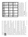
1
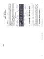
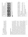
16
560-0975-03
December 2001
www.upsat.com
SL15-Series Pilot Guide
UPS Aviation Technologies, Inc.
2345 Turner Road, SE
Salem, OR 97302
SL15-Series Pilot Guide
1
2
July 1999
July 2000
January 2001
December 2001
Rev. Rev. -01
Rev. -02
Rev. -03
Patent No. 5,903,277 & 6,160,496
FAA-Approved TSO C50c, C35d
JAA-Approved JTSO-2C35d, C50c
SL15-Series Pilot Guide
Ordering Information
To receive additional copies of the Apollo SL15 User’s Guide, order part
#560-0975-03.
History of Revisions
Original Release
Visit our web page at http://www.upsat.com
Send comments about this manual by email to: [email protected]
UPS Aviation Technologies, Inc.
2345 Turner Road, S.E. Salem, OR 97302
U.S.A. Toll Free
800.525.6726
Canada Toll Free
800.654.3415
International
503.391.3411
FAX
503.364.2138
No part of this document may be reproduced in any form or by any means
without the express written consent of UPS Aviation Technologies, Inc.
UPS Aviation Technologies, Inc., II Morrow, and Apollo are trademarks of
UPS Aviation Technologies, Inc.
© 2001 by UPS Aviation Technologies, Inc. All rights reserved.
Printed in the U.S.A.
SL15-Series Pilot Guide
15
14
Notes
SL15-Series Pilot Guide
SCOPE
Power Switch (EMG-Fail Safe Operation)
Microphone Selector (All models)
SL15-Series Pilot Guide
3
The power switch also controls the audio selector panel functions, intercom, and marker beacon receiver. Unless the mic selector is in Com 3
mode, at least one of the selected audio LEDs will be on (Com 1 or Com
2).
Unit power is turned on and off by pushing the volume knob. In the OFF or
"EMG" position, the pilot is connected directly to Com 1. This allows communication capability regardless of unit condition. Any time power is removed or turned OFF, the audio selector will be placed in the fail-safe
mode.
2
SL15 controls
This section is divided into four sections covering the basic operating areas
of the SL15 systems. They are Audio Selector, Transceiver Selection, Intercom, and Marker Beacon Receiver.
This section provides detailed operating instructions for the UPS Aviation
Technologies SL15 Audio Selector Panel/Intercom System. Please read it
carefully before using the equipment so that you can take full advantage of
its capabilities.
1
GENERAL INFORMATION
OPERATION
3
Swap Mode (Switch from Com 1 to Com 2 remotely)
4
SL15-Series Pilot Guide
With a yoke mounted, momentary switch, the pilot can change from the current
Com transceiver to the other by depressing this switch. When "Swap Mode" is
active, an annunciator in the lower right corner of the unit will illuminate, indi-
3.1
NOTE
Placing the mic selector switch in the TEL position will disable pilot and copilot intercom, as the intercom circuit is transferred to the telephone use. In
crew or ISO mode, placing the switch in TEL mode removes the passengers
access to the telephone.
The copilot will also be able to transmit on COM 1 with his PTT as well.
The “TEL” position, fully CW on the mic selector switch, is the pilot’s “hook”
switch, when the system is interfaced to an appropriate approved wireless telecommunication system, such as the AirCell system. Placing the mic selector in
TEL placed the pilot microphone and headphones on the cellphone. The pilot
PTT will switch the pilot mic to the COM 1, and allow continued aircraft communications as well.
When switching from COM 1 to COM 2 while Com 2 has NOT been selected,
Com 1 audio will be switched off. In essence, switching the mic selector will
not effect the selection of Com audio.
When switching the mic selector rotary switch from COM 1 to COM 2, while
COM 2 audio had been selected, Com 1 audio will continue to be heard. This
eliminates the pilot having to switch Com 1 audio back on, if desired.
The SL15-Series has an automatic selector mode. Audio from the selected
transceiver is automatically heard in the headsets and speaker. You can check
this function by switching from COM 1 to COM 2 and watch the selected audio
light on the selector change from COM 1 to COM 2. This ensures the pilot will
always hear the audio from the transceiver he is transmitting on.
Turning the mic selector fully counterclockwise places the pilot and copilot on
Com 3. Com 3 receive audio is automatically placed in the headset (and
speaker if selected). Com 1 and/or Com 2 receiver audio can be selected to
monitor those transceivers.
The SL15 gives priority to the pilot’s PTT. If
the copilot it transmitting, and the pilot presses
his PTT, the pilot’s microphone will be heard
over the selected com transmitter.
When the mic selector switch is in the Com 1 position, both pilot and copilot
will be connected to the Com l transceiver. Only the person who presses their
Push To Talk (PTT), will be heard over the
aircraft radio. Turning the rotary switch to the
COM 2 position will place pilot and copilot on
Com 2.
SL15-Series Pilot Guide
U.S.A. Toll Free 800.525.6726
UPS Aviation Technologies, Inc.
2345 Turner Road, S.E.
Salem, OR 97302
13
10.2 Factory Service
The unit is covered by a 26-month limited warranty. See warranty information.
Call UPS Aviation Technologies, Inc. at (800) 525-6726 before you return the
unit. This will allow the service technician to provide any other suggestions for
identifying the problem and recommend possible solutions.
After discussing the problem with the technician and you obtain a Return
Authorization Number, ship the product to:
by us. This warranty is void if there is any attempt to dissemble this product
without factory authorization. This warranty gives you specific legal rights, and
you may also have other rights, which may vary from state to state. Some states
do not allow the exclusion of limitation of incidental or consequential damages, so the above limitation or exclusions may not apply to you.
All items repaired or replaced under this warranty are warranted for the remainder of the original warranty period. UPS Aviation Technologies, Inc. reserves the rights to make modifications or improvements to the product without
obligation to perform like modifications or improvements to previously manufactured products.
Concurrent Messages
12
SL15-Series Pilot Guide
10.1 Warranty
In order for the factory warranty to be valid, the installations in a certified
aircraft must be accomplished by an FAA-certified avionics shop and
authorized UPS Aviation Technologies dealer. If the unit is being installed
by a non-certified individual in an experimental aircraft, a factory-made
harness must be used for the warranty to be valid. This harness may be purchased directly from PS Engineering (865-988-9800). UPS Aviation Technologies. warrants this product to be free from defect in material and workmanship for a period of 26-months from the date of installation as recorded
in aircraft logbook and/or on FAA Form 337.
UPS Aviation Technologies, Inc. warrants this product to be free from defect in material and workmanship for a period of 26-months from the date
of installation. During this 26-month warranty period, UPS Aviation Technologies, Inc. at its option, will send a replacement unit at our expense if
the unit should display any unusual behavior.
All transportation charges for returning the defective units are the responsibility of the purchaser. All domestic transportation charges for returning
the exchange or repaired unit to the purchaser will be borne by UPS Aviation Technologies, Inc. The risk of loss or damage to the product is borne
by the party making the shipment, unless the purchaser requests a specific
method of shipment. In this case, the purchaser assumes the risk of loss.
This warranty is not transferable. Any implied warranties expire at the expiration date of this warranty. UPS Aviation Technologies SHALL NOT BE
LIABLE FOR INCIDENTAL OR CONSEQUENTIAL DAMAGES. This
warranty does not cover a defect that has resulted from improper handling,
storage or preservation, or unreasonable use or maintenance as determined
10 Warranty and Service
When a recorded message or audio annunciation is playing, the other audio
source is momentarily inhibited. For instance, if an IRS message is being
played, the audio annunciation will not begin until the IRS message is finished. Conversely, the IRS recording cannot be played as long as there is an
aural alert being played. There is no recording made if playing a recording
or annunciation.
9.3
edge).
Receiver Audio Selector (All models)
Speaker Amplifier
Public Address Function
SL15-Series Pilot Guide
4.1.1
Unswitched audio, (autopilot disconnect, altimeter warning, etc.) will come
through the speaker regardless of the speaker button position.
The "SPR" in the push-button section stands for speaker. This switch will
place all selected audio on the cockpit speaker when this switch is selected.
NOTE: Except for the unswitched audio, the speaker amplifier is not active in
the "Split Mode."
4.1
5
The users can identify which receivers are selected by noting which of the
green switch LEDs are illuminated. Push buttons labeled Nav 1, Nav 2, DME,
MKR (Marker), ADF, AUX (auxiliary), and SPR (Speaker) are "latched" type
switches. When one of these buttons is pressed, it will stay in the "in" position.
Press the switch again and it be in the "out" position and remove that receiver
from the audio.
heard, the Com l and Com 2 push-buttons are of the momentary type and do
not remain in when selected. This is also part of the "auto” function. You will
always hear the audio from the transceiver that is selected for transmit by the
rotary mic selector switch.
Because the rotary microphone selector switch controls what transceiver is being
Receiver audio is selected through two momentary and six latched, pushbutton, backlit switches. Com 1 and Com 2 are the momentary switches.
4
cating that the Mic Selector switch position is no longer current. To cancel
"Swap Mode," the pilot may either press the yoke mounted switch again, or
turn the Mic Selector Switch to the Com that is active.
Key “Click”
Split Mode
Split Mode ICS
IntelliVox® VOX-Squelch
Intercom Operation
6
SL15-Series Pilot Guide
No adjustment of the IntelliVox® squelch control is necessary. There is no
6.1
6
In split mode, the pilot and copilot are usually isolated from each other on the
intercom, simultaneously using their respective radios. Depressing the ICS button in Split Mode will activate VOX intercom between the pilot and copilot
positions. This permits intercommunication when desired between the crew.
Pressing the ICS button again disables this crew intercom function.
5.1
Split Mode does not turn off other (Nav, ADF, etc.) selected audio to pilot. However,
the copilot will only hear the selected communications receiver.
Due to the nature of VHF communications signals, and the size constraints in
general aviation aircraft, it is probable that there will be some bleed-over in
the Split mode, particularly on adjacent frequencies. UPS Aviation
Technologies makes no warranty about the suitability of Split Mode in all
aircraft conditions.
NOTE
Switching to Com 2/Com l will reverse the “Split Mode” radio selection. The
pilot will be on Com 2 and the copilot will be on Com 1.
Turning the rotary switch to COM 1/COM 2 places the SL15 into "Split Mode."
This places the pilot on Com 1 and the copilot on Com 2. An example of this
useful feature is when the pilot may want to talk to Air Traffic Control, while
the copilot may be speaking to Flight Watch. Although this mode has limitations (see below) we believe you will find this to be a useful feature.
5
Allow at least 20 seconds between turning the key click on and off.
The SL15 is equipped with a “click” function that provides an aural feedback
to the user in addition to the tactile button push. This sound can be enabled or
disabled by simultaneously holding the COM 1 and COM 2 buttons in for at
least 5 seconds. Any person hearing the radios will also hear the key click.
4.2
We recommend that the switch transfer the audio from the cockpit speaker to a
cabin speaker for public address. This will prevent feedback.
In SL15 versions above “F” serial number for the top board (2nd set of unit serial numbers) a public address function was added. To access this function, a
switch is installed to connect the top connector, pin 18, to ground. This places
the pilot microphone on the speaker output (Pin W) when the PTT is pushed.
The copilot can continue to use the selected com radio.
Internal Recorder System (Optional)
Internal Recorder Operation
Audio Messaging system (Option 1, Option 2, only)
SL15-Series Pilot Guide
11
When this option is installed, the SL15 contains six stored messages. An outside annunciator, such as an Electronics International engine gage system triggers these messages. When there is an announcement, it will be repeated every
two seconds until the remote- mounted ACK button is pushed. This stops the
played annunciation, until the next announcement is required (the next falling
9.2
To cancel the playback, press and hold the playback button for two seconds.
The next time the button is pressed, the next earlier message will be heard.
Recording is automatic; there is no action required by the pilot. To play back
the last recorded message, simply press the momentary switch associated with
the IRS. Each additional press of the button will play the preceding recorded
message. You must wait for the message to finish playing before accessing the
prior message.
9.1
Operating as a continuous loop recorder, (first message received will be the
last heard), the recorder has one minute of recording time or up to 16 messages. With its own built in VOX circuit, there are no buttons to press to start
recording. The system automatically begins to record the instant the radio becomes active. Only aircraft radio audio in pilots headset is recorded and only
the pilot will hear the playback audio.
The Intercom Recording System (referred to here as the IRS) is a digital recording
system allowing automatic storage and playback of aircraft radio traffic.
9
In units with serial numbers above “F” series in the first set of numbers, a
marker mute function was added. Pressing the marker mode select down (to
“T/M”) will cause the marker audio to mute for that beacon. The next beacon
received will re-activate the audio.
A three-position switch is used to set the receiver sensitivity and to test the indicator lamps. Use "HI" sensitivity initially. This allows you to hear the outer
marker beacon about a mile out. Then select the “LO” sensitivity to give you a
more accurate location of the Outer Marker. The momentary down switch position is marker test, labeled "T/M" and illuminates all three lamps simultaneously to assure the lamps (internal and external) are in working order. TST
does not activate MM sense output.
justment located on the top of the unit. See Section 2.5
Marker Beacon (SL15)
SL15-Series Pilot Guide
SL15-Series Pilot Guide
10
Intercom Modes
The lower switch on the left side is a 3-position mode switch that allows the
pilot to tailor the intercom function to best meet the current cockpit situation.
6.3
7
Mono headsets in Stereo Installation
All passenger headsets are connected in parallel.
Therefore, if a monaural headset is plugged in to a
SL15 Stereo installation, one channel will be
shorted. Although no damage to the unit will occur,
all passengers will lose one channel, unless they
switch to the “MONO” mode on the headset.
6.2.1
Adjust the radios and intercom volume for a comfortable listening level for the
pilot. Most general aviation headsets today have built-in volume controls;
therefore, passenger volume can be adjusted at the headset. If desired, passenger volume level can be adjusted by a screwdriver adjustment at the top of the
tray. See the installation manual for details.
The volume control knob adjusts the loudness of the intercom for the pilot and
copilot only. It has no effect on selected radio levels, music input levels or passengers' volume level.
The audio from the Marker Beacon Receiver can be heard by selecting the
"MKR" push-button switch. To adjust the volume level, there is a service ad-
The White lamp, labeled "I," is the Inner marker and has a 3000 Hertz 'dot'
tone. The lamp and tone will be keyed at a rate of six times per second.
The Amber lamp, labeled "M," is the Middle Marker lamp and is coupled with a 1300 Hertz tone.
It is keyed alternately with short 'dot' and long 'dash' bursts at 95 combinations
per minute.
The Blue lamp, labeled "O," is the Outer Marker lamp and has an associated
400 Hertz 'dash' tone. The lamp and tone will be keyed at a rate of two tones/
flashes per second when
the aircraft is in the
range of the Outer
Marker Beacon.
The optional Marker Beacon Receiver uses visual and audio indicators to alert
you when the aircraft passes over a 75 MHz transmitter.
8
Volume Control
6.2
Because the cell phone uses an intercom circuit, all stations on that circuit will
lose intercom capability when the cell phone is in use.
NOTE
For optimum microphone performance, UPS Aviation Technologies recommends installation of a Microphone Muff Kit from Oregon Aero (1-800-8886910). This will not only optimize VOX performance, but will improve the
overall clarity of all your communications.
The IntelliVox® is designed to work with normal aircraft cabin noise levels (70
dB and above). It loves airplane noise! Therefore, it may not recognize speech
and clip syllables in a quiet cabin, such as in the hangar, or without the engine
running. This is normal.
It is also a good idea to keep the microphone out of a direct wind path. Moving
your head through a vent air stream may cause the IntelliVox® to open momentarily. This is normal.
NOTE
For consistent performance, any headset microphone must be placed
within ¼-inch of your lips, preferably against them. (ref: RTCA/DO-214,
1.3.1.1 (a)).
The system is designed to block continuous tones, therefore people humming
or whistling in monotone may be blocked after a few moments.
field adjustment. Through three individual signal processors, the ambient noise
appearing in all six microphones is constantly being sampled. Non-voice signals are blocked. When someone speaks, only their microphone circuit opens,
placing their voice on the intercom.
In all cases, only the pilot (and copilot in ALL or CREW) will hear the cellphone ring. At that time they can chose to allow a passenger to take the call, or
answer the phone.
In ISO intercom mode, when the SL15 is in the TEL mode, the pilot position
is in the "Phone Booth." Only the pilot will hear the telephone, and only he will
be heard. He will also have access to Com 1, and will transmit on that radio
using the PTT. All selected audio is provided. If any other passenger goes “off
hook” they will hear the phone.
In CREW mode, the pilot and copilot are may use the telephone, with their
respective hook switch (the pilot selects TEL on the mic selector). Any passenger who places their switch into the off-hook position will also have access to
the phone, and all four passengers will hear the conversation.
When the intercom is in ALL mode, the pilot can speak on the phone only if
the mic selector switch is in TEL position. All intercom positions will hear the
telephone conversation. If any passenger places his or her switch into the “offhook” position all passengers will also be heard on the phone. All will hear
selected audio. Com 1 audio is automatically heard in the headsets. The pilot
and copilot will have transmit capability on Com 1, simply by using their respective PTT switch.
switches mounted adjacent to the headset jacks.
Entertainment Input
8
6.3.2
Soft Mute and Soft Mute inhibit
SL15-Series Pilot Guide
It is also possible to use only one entertainment input device for both entertainment inputs. However, it is suggested that a switch (DPDT) be installed between the single entertainment device and entertainment input #1. This will
allow the pilot and copilot decide if they hear entertainment while in the Crew
mode.
When in the ALL mode, pilot and copilot will hear Entertainment 1 input while
all passengers will hear the Entertainment 2 source. While in the CREW mode,
pilot and copilot will hear entertainment input #1 while the passengers may
listen to entertainment input #2.
While in the ISO (Isolate) mode, the copilot will hear Entertainment 1 while
the four passengers will hear Entertainment #2. The pilot will hear entertainment 1, at a muted level. In normal operation, whenever a person speaks, or if
the aircraft radio becomes active, the music will automatically mute and then
will gradually return to the original listening level when the intercom or radio
conversation ceases.
The audio selector panel has provisions for two separate entertainment input
devices. They operate independently in the SL15. The volume control does not
affect music level.
6.3.1
Anytime the SL15 is in either the COM 1/COM 2, COM 2/COM 1 ("Split
Mode"), the pilot and copilot intercom is controlled with the ICS button. The
passengers will maintain intercommunications, but never hear aircraft radios.
CREW (Down Position): Pilot and copilot are connected on one intercom channel and have exclusive access to the aircraft radios. They may also listen to Entertainment 1. Passengers can continue to communicate with themselves without interrupting the Crew and also may listen to Entertainment 2.
ALL: (Middle Position): All parties will hear the aircraft radio and intercom.
Crew will hear Entertainment 1, passengers will hear Entertainment 2. During
any radio or intercom communications, the music volume automatically decreases. The music volume increases gradually back to the original level after
communications have been completed.
ISO: (Up Position): The pilot is isolated from the intercom and is connected
only to the aircraft radio system. He will hear the aircraft radio reception (and sidetone during radio transmissions). Copilot will
hear passengers’ intercom and Entertainment 1, while passengers
will hear copilot intercom and Entertainment 2. Neither will hear
aircraft radio receptions or pilot transmissions.
The description of the intercom mode function is valid only when the unit is
not in the "Split" mode. Then, the pilot and copilot intercom is controlled with
the ICS button.
Pilot
Co-Pilot
A/C Radio
Entertainment
#1
Pilot
Co-Pilot
A/C Radio
Passengers
Entertainment
#1
Co-Pilot
Pilot
A/C Radio
Entertainment
#1
Co-Pilot
Pilot
A/C radio
Passengers
Entertainment
#1
Co-Pilot and
passenger
intercom Entertainment #1
Co-Pilot
Hears
Passengers
Entertainment
#2
Passengers
Pilot
Co-Pilot
A/C Radio
Entertainment
#1
Passenger and
Copilot intercom
Entertainment
#2
Passenger
Hears
Pilot does not
have phone
access, unless
the mic sel is in
the TEL position. Passengers have
phone through
an on/off Hook
Switch.
Passengers
hear phone
All have access
to phone
through Hook
Switch. Pilot
access through
TEL switch. All
hear telephone
audio if off hook.
“Phone Booth”
mode. Pilot has
exclusive use of
the telephone.
In TEL, Pilot
connected to
Com 1 for PTT
Tx and receive.
Others hear Tel,
if off hook.
Telephone
This mode allows the pilot
and co-pilot to
concentrate on
flying, while the
passengers can
communicate
amongst themselves.
This mode allows all on board
to hear radio
reception as well
as communicate
on the intercom.
Music and intercom is muted
during intercom
and radio communications.
This mode allows the pilot to
communicate
without the others bothered by
the conversations. Copilots
and passengers
can continue to
communicate
and listen to
music.
Comments
Telephone Mode
SL15-Series Pilot Guide
9
(When interfaced with a Each intercom position has a "hook switch." The pilot's hook switch is the "TEL" mode on the audio panel, the others are discrete
7
The passenger music, source #2, can be placed in the Karoake mode if a remote switch is installed in the aircraft. See wiring information for details.
The front panel ICS switch controls muting of entertainment source #1 (for
pilot and copilot). Pushing this button places the ICS in Karoake (or sing
along) mode, which inhibits the soft mute feature. This allows the music to
continue uninterrupted by intercom or radio traffic when cockpit workload is
appropriate. Pushing the button again will release the mute inhibit function.
missed due to entertainment playing. When there is radio reception or intercom
conversation, the music level is dropped to a low, or background level. When
the radio or intercom traffic ceases, the level gradually returns to normal.
Crew
All
Pilot Sidetone
(during radio
transmission)
Entertainment
1 is muted
Pilot Hears
Isolate A/C Radios
Mode
The Soft Mute feature assures that the aircraft radio transmissions will not be