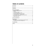
1
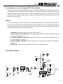
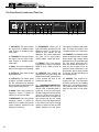
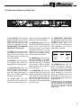
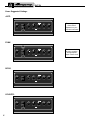
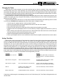
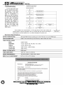
Owner’s Guide
for the
SVT-CL
Bass Amplifier
1 2 3 4 5
0dB
-15dB
HI
STANDBY/
POWER/
FAULT
LO
INPUTS
GAIN
ULTRA HI/LO
BASS
MIDRANGE
FREQUENCY
TREBLE
MASTER
STANDBY
POWER
SVT-CL
Table of Contents
Important Safeguards and Precautions . . . . . . . . . . . . . .2
Introduction . . . . . . . . . . . . . . . . . . . . . . . . . . . . . . . . . . .3
Features . . . . . . . . . . . . . . . . . . . . . . . . . . . . . . . . . . . . .3
System Block Diagram . . . . . . . . . . . . . . . . . . . . . . . . . .3
The Front Panel Controls and Their Use . . . . . . . . . . . . .4
The Rear Panel Controls and Their Use . . . . . . . . . . . . .5
Some Suggested Settings . . . . . . . . . . . . . . . . . . . . . . . .6
Changing the Tubes . . . . . . . . . . . . . . . . . . . . . . . . . . . .7
Troubleshooting . . . . . . . . . . . . . . . . . . . . . . . .back cover
Technical Specifications . . . . . . . . . . . . . . . . . .back cover
Important Safeguards and Precautions
All Ampeg products are designed for continuous safe operation, as long as common sense is used and steps are taken to help avoid certain problems. Abiding by the following rules can help prevent damage to your amplifier, yourself and others.
• The amp is equipped with a three-prong AC power cord. To reduce the risk of electrical shock, NEVER remove or otherwise attempt to defeat
the ground pin of the power cord.
• Connect the amp ONLY to a properly grounded AC outlet of the proper voltage for your amp. If no grounded outlet is available, use only an
approved method of adapting to a two-prong AC source.
• Avoid sudden temperature extremes, rain and moisture. Also, avoid sudden and intense impact. (If the unit has been subjected to any of the
preceding abuses, have it looked at by an authorized service center.)
• NEVER set the amp on a support that might give out under its weight.
• Always keep the total impedance at or above the rated load.
• Unplug the amp before cleaning it. NEVER spray liquid cleaners onto the unit. Wipe the unit with a slightly dampened, lint-free cloth to remove
dirt and film.
• Don’t use the amp if it has sustained damage to the chassis, controls, or power cord. Refer the unit to an authorized service center for inspection.
• Amplifiers capable of producing high volume levels are also capable of inflicting permanent hearing loss or damage, if the exposure to such
levels is prolonged. Such damage is progressive and irreversible! Caution is advised and ear protection recommended when playing at
extremely loud levels.
The chart below shows the U.S. Government Occupational Safety and Health Administration (OSHA) regulations which were in effect at the time of
this publication for permissible noise exposure, per 29CRF1910, Table G-16.
SOUND LEVEL dBA
SLOW RESPONSE
DURATION PER DAY
IN HOURS
SOUND LEVEL dBA
SLOW RESPONSE
DURATION PER DAY
IN HOURS
90
92
95
97
100
8
6
4
3
2
102
105
110
115
1-1/2
1
1/2
1/4 or less
According to OSHA, any exposure in excess of those listed above could result in some hearing loss.
CAUTION
ATTENTION
VORSICHT
RISK OF ELECTRIC SHOCK
DO NOT OPEN
RISQUE D'ELECTROCUTION
NE PAS OUVRIR
ELEKTRISCHE SCHLAGGEFAHR
NICHT OFFENEN
CAUTION: TO REDUCE THE RISK OF ELECTRIC SHOCK,
DO NOT REMOVE COVER.
NO USER-SERVICEABLE PARTS INSIDE.
REFER SERVICING TO QUALIFIED SERVICE PERSONNEL.
ATTENTION: POUR REDUIRE D'ELECTROCUTION NE PAS
ENLEVER LE COUVERCLE. AUCUNE PIECE INTERNE N'EST REPRABLE
PAR L'UTILISATEUR. POUR TOUTE REPARATION, S'ADRESSER A UN
TECHNICIEN QUALIFIE.
VORSICHT: ZUR MINIMIERUNG ELEKTRISCHER SCHLAGGEFAHR NICHT
DEN DECKEL ABENHMEN. INTERNE TEILE KONNEN NICHT VOM
BENUTZER GEWARTET WERDEN. DIE WARTUNG IS QUALIFIZIERTEM
WARTUNGSPERSONAL ZU UBERLASSEN.
THIS EQUIPMENT HAS BEEN DESIGNED AND ENGINEERED TO PROVIDE SAFE AND RELIABLE OPERATION. IN ORDER TO PROLONG THE
LIFE OF THE UNIT AND PREVENT ACCIDENTAL DAMAGES OR INJURY, PLEASE FOLLOW THESE PRECAUTIONARY GUIDELINES:
CAUTION: TO REDUCE THE RISK OF ELECTRIC SHOCK, DO NOT OPEN CHASSIS; DO NOT DEFEAT OR REMOVE THE GROUND PIN OF THE
POWER CORD; CONNECT ONLY TO A PROPERLY GROUNDED AC POWER OUTLET.
WARNING: TO REDUCE THE RISK OF FIRE OR ELECTRIC SHOCK, DO NOT EXPOSE THIS EQUIPMENT TO RAIN OR MOISTURE.
CAUTION: NO USER-SERVICEABLE PARTS INSIDE. REFER SERVICING TO QUALIFIED SERVICE PERSONNEL.
CAUTION: OUR AMPLIFIERS ARE CAPABLE OF PRODUCING HIGH SOUND PRESSURE LEVELS. CONTINUED EXPOSURE TO HIGH SOUND
PRESSURE LEVELS CAN CAUSE PERMANENT HEARING IMPAIRMENT OR LOSS. USER CAUTION IS ADVISED AND EAR PROTECTION IS RECOMMENDED IF UNIT IS OPERATED AT HIGH VOLUME.
2
EXPLANATION OF
GRAPHICAL SYMBOLS:
"DANGEROUS VOLTAGE"
= "DANGER HAUTE TENSION"
"GEFAHLICHE SPANNUNG"
"IT IS NECESSARY FOR THE USER TO REFER TO THE INSTRUCTION MANUAL"
= "REFERREZ-VOUS AU MANUAL D'UTILISATION"
"UNBEDINGT IN DER BEDIENUNGSANLEITUNG NACHSCHLAGEN"
SVT-CL
An Introduction to your new Ampeg SVT-CL Bass Amplifier
The harmonically rich sound and legendary performance of the classic AMPEG SVT are redefined in the SVT-CL.
This dynamically powerful bass amp delivers a thunderous 300 watts of unsurpassed quality, reliability and tonal
flexibility, offering the classic vibrance of tubes as well as contemporary features. All of the features and controls
of your SVT-CL are covered in detail within the pages of this owner’s guide. We recommend going over them
before you use the amplifier.
Features
In the world of high performance bass amps, SVT amplifiers stand alone. In true Ampeg tradition, the SVT-CL
offers you more power, performance and flexibility than any other amplifier in its class. Listed below are some of
the outstanding features of your new amp: features which set it apart from the competition! Additional information
on these features can be found on the pages indicated.
• -15dB INPUT: This feature is perfect for “active” basses (page 4).
• ULTRA LO AND ULTRA HI SWITCHES: These enable you to tailor your sound in many different ways at
the touch of a button (page 4).
• 5-POSITION FREQUENCY SELECTOR: Take your pick from the five center frequency points to get just
the right midrange voice (page 4).
• BIAS ADJUSTMENT CONTROLS: These controls allow you to adjust the tube bias for proper operation
(pages 5 & 7).
• SLAVE OUT: Use for powering another amp from the SVT-CL’s preamp (page 5).
System Block Diagram
PWR AMP
INPUT
BAL
OUT
SLAVE
OUT
IMPEDANCE
4 OHMS
2 OHMS
POWER
AMP
1/4" JACK
PREAMP
OUT
0dB INPUT
BIAS
ADJUST
BUFFER
1/4" JACK
MASTER
GAIN
BASS TREBLE
-15dB INPUT
ULTRA
HI
ULTRA
LO
SPEAKER
OUTS
POWER AMP
PROTECTION
MID
1+
1-
FREQUENCY
2+
POWER
STANDBY
FAULT
®
2- SPEAKON
JACK
BIAS
INDICATORS
3
SVT-CL
The Front Panel Controls and Their Use
1 2 3 4 5
0dB
-15dB
HI
STANDBY/
POWER/
FAULT
LO
INPUTS
GAIN
ULTRA HI/LO
BASS
MIDRANGE
FREQUENCY
TREBLE
MASTER
STANDBY
1
2
3
4
5
1. 0dB INPUT: This jack accepts
the signal from a passive instrument through a shielded instrument cable.
2. -15dB INPUT: This jack accepts
the signal from an active instrument through a shielded instrument cable.
3. GAIN: This control adjusts the
basic level of signal in the preamp.
4. ULTRA HI: This switch boosts
high frequencies.
5. ULTRA LO: This switch, when
engaged, provides emphasis to
the low frequencies by boosting
the low frequencies and selectively
cutting the mid frequencies.
6. BASS: This is the primary low
frequency control. It allows for
12dB of cut or boost at 40Hz.
7. MIDRANGE: This is the primary
midrange control. It allows for
20dB of cut or 10dB of boost at the
center frequency selected by the
Frequency control (8).
4
6
7
8
9
10
8. FREQUENCY: Allows you to
select the center frequency for the
Midrange control (7), giving you a
choice of five “voices” for the
Midrange. The center frequencies
are (from left to right) 220Hz,
450Hz, 800Hz, 1.6kHz and 3kHz.
9. TREBLE: This is the primary
high frequency control. It allows for
20dB of cut or 15dB of boost at
4kHz.
10. MASTER: This controls the
signal level to the power amp and
therefore the overall listening level.
It also controls the level to the
Preamp Out jack (20).
11. STANDBY/POWER/FAULT
INDICATOR LED: This is a multifunction LED. In Standby Mode, it
glows red. In the On mode (when
the high voltage comes on) it glows
green. If it does not turn green in
the On mode, there is no high voltage present and the unit needs
servicing. If the amp detects a fault
in the power tube circuit, the high
voltage is turned off and the LED
flashes between red and green.
11
12
POWER
13
This usually indicates a bad power
tube. The amp will remain in this
condition until the unit is turned off.
12. STANDBY: The Standby mode
allows the tubes to warm or remain
warm without high voltage being
applied to them. This extends tube
life. This switch should be OFF
when first turning the amplifier on.
Allow the unit to warm up for 20
seconds before switching to the
ON position. During short periods
of non-use, the amp should be put
into Standby mode.
13. POWER: This supplies AC
power to the unit. Turn this switch
on before turning on the Standby
switch (#12), as explained above.
This switch must be turned off to
reset the amp after a Fault condition.
SVT-CL
The Rear Panel Controls and Their Use
14
15 16
14. AC LINE IN: Firmly plug the
supplied AC power cord into this
socket, pushing it in until it is fully
seated. Plug the male end of the
cord into a grounded AC outlet.
DO NOT DEFEAT THE GROUND
PRONG OF THE AC PLUG!
15. FUSE: This protects the unit
from damage due to overload conditions or power line surges. If the
fuse blows, replace it only with the
same size and type.
16. POLARITY: Place this switch
in the position that provides the
least electrical buzz from the unit.
17. BIAS SECTION: These two
controls and sets of LEDs allow the
user to properly bias the power
amp. See “Setting Tube Bias” on
page 7 for a complete description
of how to use this section.
18. SLAVE OUT: This jack
receives the same signal that is
being sent to the power amp. It is
17
18
useful for powering another amp
(slave) from this unit’s preamp.
19. BALANCED OUT: This XLRtype jack is the output at the power
amp in. Thus, it will include any
processing done in the Preamp
Out/Power Amp loop (16, 17). This
signal can be used to feed an
external power amplifier, mixing
console or house PA system.
20. PREAMP OUT: This jack carries the post-Master (10) signal.
Using this jack does not break the
path to the power amp. This signal
can be used to feed an external
power amplifier, mixing console or
house PA system.
21. POWER AMP IN: This jack
accepts a signal to be sent to the
power amp and the Slave Out jack
(18). Using this jack breaks the
path from the signal that was present at the Preamp Out jack (20).
This can be used as a post-Master
(10) patch point.
19
21 20 22
23
22. IMPEDANCE SELECTOR:
Use this switch to match the output
impedance of the amp to the
speaker(s) being used (2 or 4
ohms). For help in deciding the
total impedance of your system,
consult the chart below.
Cabinet
Impedance
Number of
Cabinets
2 ohms
4 ohms
4 ohms
8 ohms
8 ohms
1
1
2
2
4
Total
Impedance
2
4
2
4
2
ohms
ohms
ohms
ohms
ohms
23. SPEAKER OUT: Two 1/4”
phone jacks and one Speakon®
jack are provided for connecting
speakers to the unit. These jacks
are wired in parallel to each other.
When operating at or near full
power, the Speakon® jack is recommended for use over the 1/4”
jacks due to its higher current handling capability.
NOTE: In some areas 1/4” speaker jacks
are not acceptable for use on amplifiers
with high output power levels. For this
reason the 1/4” jacks on your amplifier
may not be accessable – use the
Speakon® jack.
5
SVT-CL
Some Suggested Settings
JAZZ:
1 2 3 4 5
HI
LO
GAIN
ULTRA HI/LO
BASS
MIDRANGE
FREQUENCY
TREBLE
MASTER
IN
The setting of the
Gain control
depends on your
particular instrument.
FUNK:
IN
1 2 3 4 5
HI
LO
GAIN
ULTRA HI/LO
BASS
MIDRANGE
FREQUENCY
TREBLE
MASTER
TREBLE
MASTER
TREBLE
MASTER
IN
ROCK:
1 2 3 4 5
HI
LO
GAIN
ULTRA HI/LO
BASS
MIDRANGE
FREQUENCY
COUNTRY:
1 2 3 4 5
HI
LO
GAIN
ULTRA HI/LO
IN
6
BASS
MIDRANGE
FREQUENCY
The Master should
be set to produce
the appropriate
output volume level.
SVT-CL
Changing the Tubes
Tubes wear out in direct proportion to how often and how hard you play the amplifier. Power tubes should be
checked at least once a year - more frequently if you use the amplifier nearly every day. When power tubes wear out,
the amplifier will begin to grow weak, lack punch, fade up and down, or lose highs and lows. Power tubes work together in a push/pull configuration and should all be replaced at the same time with matched or balanced tubes. Your dealer can recommend the best replacement tubes for your amplifier.
Preamp tubes aren’t worked as hard as power tubes and typically last longer. When a preamp tube wears out, the
amplifier may squeal, get noisy, lose gain and sensitivity, or just quit working. A service center can determine which
tube(s) may need replacing.
To get to the power tubes in the SVT-CL, the rear screen must be removed and the tube retainer(s) must be moved
out of the way. Qualified service persons may follow these steps to change the tubes:
•
•
•
•
•
Turn the amp off, unplug it and let it cool for at least 5 minutes.
Remove the screws which hold the perforated metal screen to the rear of the cabinet.
Set the perforated metal screen aside.
Remove the tube retainer(s) by lifting them off the tube(s) and moving them to one side.
Grasp the tube at its top and gently work it out of its socket by rocking it slightly back and forth as you lift up
on it.
• When inserting new output tubes, align the tab in the tube’s plastic base with the slot in the socket and press
the tube gently but firmly into place by pushing down on its top.
• Replace the perforated metal screen and tighten its screws.
• Power up the amplifier and let it sit for at least 20 minutes. Bias the amplifier as directed in the section below.
Setting Tube Bias
Allow the unit to warm up at proper AC line voltage for at least 20 minutes. With no input signal present, adjust each
control so that only the associated green LED is lit. The controls may be slightly interactive. If neither LED is lit, the
amp is over biased.This will result in some distortion in the power amp and a generally thin sound. If the green and
red LED are lit, the amp is under biased and too much current is flowing to the power tubes. This will give a big, full
sound but will also reduce the life of the power tubes. Once set, the controls should not have to be changed except as
needed for tube replacement, or to compensate for tube aging. Note that the AC line voltage may vary from place to
place and the LEDs will read slightly different. There is no need to fiddle with this every other day. Note that it is normal for the red LEDs to light when there is a signal present. Bias 1 Control adjusts the three left (as seen from the rear)
power tubes. Bias 2 Control adjusts the three right power tubes. By observing the LEDs as the Bias Controls are slowly rotated clockwise, a number of tube problems can be diagnosed by the user:
Condition
Green comes on, then red
Problem
No problem
Solution
The longer the green LED is on before the
red LED comes on – the better matched the
tubes are.
Red comes on, then green
Tubes not properly matched
Set slighty before green comes on, obtain
matched tubes when possible.
Red comes on, no green
One or more tubes are non-functioning
Check to make sure tubes are all seated
properly; if so, find and replace bad tube(s).
None on
Possibly no high voltage or bad
Bias Control or bad tube(s)
Have unit checked by a service technician.
Both on all the time
Possible bad Bias Control or bad tubes
Have unit checked by a service technician.
If the tubes are bad enough to cause damage to the unit, the Fault Indicator (#11, Front Panel) will signal and the unit
will shut down.